Table of Contents
Advertisement
Quick Links
Advertisement
Table of Contents

Related Manuals for Philco DVCR101


Summary of Contents for Philco DVCR101
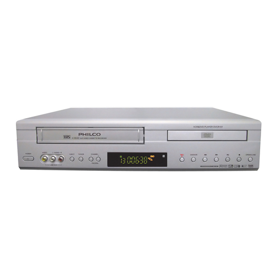
- Page 1 DVCR101 DVD & VCR PLAYER SERVICE MANUAL...
- Page 2 Specifications for DVCR101 General Information Specifications ˛ (M U ˛ (M U ? ? ? ? ˛ (M U ˛ (M U Model DVCR101 _ ¸ System Name VCR&DVD PLAYER 2ˇ4‡ Æ/˜ Brand PHILCO Package 1 Packing Case > ª...
- Page 3 DVD+VCR External Dimensions(W h H h D) 430mm×91mm×355mm (W h H h D) Mass 5.7kg B G£ Body Color Silver Gray 1 Np8F J˚&D8F Power Supply 120V AC ¨60Hz o+ + $d Power Consumption #\5º s)[ Material for Plastic Panel ABS ˜V-0 Flame Class ¯...
- Page 4 FCC, FDA Warning Mark and Serial Number of UL Operating Temperature 5 ~35 ˜Humidity 80%MAX ¯ FF/REW Time 0 220 s Input/Output Eg 9 Eg 9 /Eg ˛ y • Eg 9 Eg 9 Eg ˛ y • Eg ˛ y • Eg ˛...
-
Page 5: Kodak Picture Cd
Dolby Pro Logic DTS Digital Out DTS Digital Surround HDCD KODAK PICTURE CD MPEG 4 Integrate REMOTE (VCR / DVD) Progressive-Scan Output ˜ YPbPr ¯ Power off, standby, eject No Memory Playback + ˆ Y ˆ ˛ § ·A Automatic upgrading Don’t power off or operate the unit ,‹7 | 4{E /... - Page 6 TAPE WIDTH 12.65mm ˜1/2inch ¯ ¨ VHS Playtime SP 2hrs × 3times 6hrs ˜use of T120 tape ¯ Standby Power <5W Adjustable Range for Volume Nonadjustable M˙G£A× H8× ¨ Æ ˆA× Pro logic Output Channel 3 or 4 CH Received channels VHF 2-13CH/UHF 14-69CH/Cable 1-125 Default 5 , (...
- Page 7 BRIGHTNESS CONTRAST VCR F… F… F… F… OSD display Auto Power off Output Channel Audio Specifications M˙Ne M˙Ne M˙Ne M˙Ne SLP ˜ ˜ ˜ ˜EP ¯ ¯ ¯ ¯ HIFI S/N(1kHz) 1 85 dB 1 42dB 1 40dB 1 60dB >!¤...
- Page 8 Horizontal Resolution 1 450 " G# D z S Video Y 1.0 f 0.2 Vp-p ¨75 ¡ L Q O R D G Output Level Eg ˛+ G Chrominance 0.286 Vp-p f 10% ¨75 ¡ L Q O R D G Y:0.7 f 0.2Vp-p ¨75 ¡...
-
Page 9: Vcr& Dvd Player
Owner’ Manual ‘ ‘ ‘ ‘ Language 8¯A` ˆ " 'A` ˆ?S)`(-A` English, French, Spanish Packing Case > 1 > 1 > 1 > 1 Internal Dimensions (Refer to Structural Drawing for Detail L h W h H ˜A”? 4§ X ¯... - Page 10 Signal process and signal flow for DVCR101 The player is composed of main PCB, decoding-servo PCB, controlling PCB and power PCB. VIDEO input VIDEO output AUDIO output AUDIO input AUDIO BU4053BCF AN3663FBP VIDEO Video selection High frequency selection and Hi-Fi...
- Page 11 IN DATA OUT, IR. So both DVD and VCR modes can be played back at the same time. When DVD video signal is recorded, the signal will be output by main CPU, that’s how the customer records the program while watching DVD. ICs on DVCR101 Circuit PCB Model...
-
Page 12: Important Safety Instructions
Important Safety Instructions 1.Read Instructions - All the safety and operating instructions should be read before the product is operated. 2.Retain Instructions - The safety and operating instructions should be retained for future reference. 3.Heed Warnings - All warnings on the product and in the operating instructions should be adhered to. 4.Follow Instructions - All operating and use instructions should be followed. - Page 13 and unused for long periods of time, unplug it from the wall outlet and disconnect the antenna or cable system. This will prevent damage to the product due to lightning and power-line surges. 17.Power Lines - An outside antenna system should not be located in the vicinity of overhead power lines or other electric light or power circuits, or where it can fall into such power lines or circuits.
-
Page 14: System Circuit
I. VCR and Front panel 1. SYSTEM CIRCUIT A. LED DISPLAY No LED display. Is 5V obtained at IC701 Check PCB Pattern. pin #9, 25? Oscillation at IC701 pin #1? Exchange IC701. Specific GRID/SEG doesn’t function. Check IC 701 pin #22~24, 27, GRID output at PORT of IC701? 28, 30, 31... - Page 15 B. No power compensation. No power compensation Voltage of power fail (IC601 Check R625. pin#100) at micom is 0.7V over? More than 3.2V is maintained Check RESET circuit. for 1 minutes at IC601 pin#37 during Power Cord Open. Exchange IC601. C-1.
-
Page 16: Playback Screen
C-2. Bad playback quality (2) Noise appears on the Full Recheck step C-1 (Bad playback screen. playback quality (1 Are SW pulse and HA SW Are there SW, HA SW pulse at Check IC601. normal? IC601 pin #16, 18? Check PCB Pattern. ENVE Wave at PT01 pin #4? Check HEAD AMP connector and HEAD. - Page 17 E. No CASSETTE Loading Cassette tape isn’t inserted. Is 5V voltage obtained at Check at ON/OFF 14. Loading parts IC601 pin#82? Check (D822, C822). Is 14V voltage obtained at Check D851 and POWER Capstan Motor pin#8? circuit. Is 12V voltage obtained at each Connect Capstan and Loading Motor.
- Page 18 G. DRUM Motor stops DRUM Motor stops. Is 14V voltage obtained at Check ON/OFF 14V P603 pin#8? (D851). Is DRUM PWM fit to IC 601 Check DRUM PG/FG(IC601 90). pin#76? Is 1.2V voltage obtained at Check R657, R658,C661,C668. P603 pin#12? Check Capstan Motor and DRUM Motor.
-
Page 19: Video Circuit
2. VIDEO CIRCUIT A.EE SCREEN doesn’t appear EE screen doesn’t appear. Is Video signal input at IC401 Check LINE JACK and PIF circuit. pin#30,32 and IC402 pin#2,12? Check DVD circuit. Is 5V obtained at IC401 Check POWER circuit. pin#23,24,45,52? Is C.S.. DATA CLOCK signal Check IC601 pin#70,71,72 Input pin#53,54,55 of IC401? Is signal output from pin#26... - Page 20 B. Playback picture doesn’t appear Playback picture doesn’t appear. Is C.S.. DATA CLOCK signal Check IC601 pin#70,72,74 Input pin#53,54,55 of IC401? Is envelope output from Is 5V supplied at IC401 Check Power circuit. IC401 pin#14 pin#68? Is VIDEO SW Pulse input at Check IC601 pin#18 IC401 pin#57? Clean head or change head...
- Page 21 C. No recording No recording. Check EE MODE. Is luminance and color signal Is signal input at IC401 pin# output from IC401 pin#46,58? 30, 32 and IC402 pin#2,12? Is 5V obtained at IC401 Check POWER circuit. pin#68 Check IC601 pin#18 Is VIDEO SW Pulse input at IC401 pin#57? Is REC signal input at IC401...
- Page 22 D. No OSD(On Screen Display) appears No OSD appears. Is 5V obtained at IC601 pin# Check POWER circuit. 53, 98, 99? Is Video signal output at Is Video signal input at IC601 Replace IC601. IC601 pin#52? pin#50? Check IC 601. Check IC 601.
- Page 23 E. No DVD Video EE screen doesn’t appear Is signal output at P102 Check FFC CABLE & pin# 13? Is signal at IC402 Check PCB Pattern pin#2? Remark previous 3-A No COMPONENT signal at JK102 Check FFC CABLE Is signal output at P102 pin #19,20,21? &DVD Is signal output at...
-
Page 24: Audio Circuit
3. AUDIO CIRCUIT A. No sound in EE mode A. a. RF EE No sound in RF EE mode. Is 12V obtained at IC901 pin#58? Check POWER circuit. Is 5V obtained at IC901 pin#25,40 and IC401 pin#77? Is the signal supplied to Check RF101 pin#48 of IC901? Are CLK and DATA obtained... - Page 25 A. b. LINE1 EE No sound in LINE1 Is 12V obtained at IC901 pin#58? Check POWER circuit. Is 5V obtained at IC901 pin#25,40 and IC401 pin#77? Is Audio signal at IC901 Check Input LINE1 JACK pin#9, 14 in LINE1 mode? Are CLK and DATA obtained Replace IC901 at IC901 pin#42,43?
- Page 26 A. c. LINE2 EE No sound in LINE2 Is there Audio at IC901 Check Input LINE2 JACK. pin#2,4 in LINE2 mode? Is LINE2 Audio signal output Is 12V obtained at IC901 Check POWER circuit. pin#58? at IC901 pin#53,57? Check Output JACK. Replace IC901 - 25...
- Page 27 A. d. DVD EE No sound in DVD EE mode. Is there DVD Audio at Check DVD Loader. P102 pin#1, 3? Is 12V obtained at ICD04 Check POWER circuit. pin#8? Is DVD Audio signal output Check ICD04. at ICD04 pin# 1,7? Replace IC901 Is DVD signal output at IC901 pin#53,57 ?
- Page 28 B. No Hi-Fi playback audio (PLAY MODE) Is the ENVE level of IC901 pin# Check PRE-AMP 29,30 more than 200mVp-p? circuit Is A.SW Signal input at IC901 Check A.SW at IC601 pin#19 pin#27? Is the voltage of IC901 pin#28 Change IC 901 above 5V? Is Playback Audio signal Is 12V obtained at IC901...
-
Page 29: Head Cleaning
c. No HIFI playback in record/playback mode(REC MODE) Check ICD04(DVD) Block Check Input LINE1 JACK. at IC901 pin#9,10,14, Check Input LINE2 JACK. 15, 2, 4. Check ICD02(DVD) Block. Is there Audio signal? REC ' H' BASE voltage at Check IC601 pin#22 Q409 is 5V? Q201 is 5V? Is FM OSC signal at IC901 Replace IC901... - Page 30 mode) E. No NORMAL AUDIO playback in record/playback mode(Check in REC No Normal Audio playback in record/playback mode Check ICD04(DVD) Block Check Input LINE1 JACK. at IC901 pin# 9, 10,14 Check Input LINE2 JACK. 15, 2,4 Check ICD02(DVD) Block. Is there Audio signal? Is there recording signal at Check IC901.
- Page 31 Typical maintenance samples Example1 [Symptom]: After the player is powered on, DVD or VCR indicator will keep lighting. The buttons don’t response. [Analyze]: Power supply is normal, but the system program doesn’t work normally, and so does the CPU (IC601). No signal is output at testing switch (P606) on , and running mechanism no lifting voltage is output.
- Page 32 Symptom Remote control doesn’t function, instead the player still works by pressing buttons on the front panel. [Analyze] Remote sensor and the circuit have trouble. First test if +5V voltage output at remote sensor P701 with OSC. Then test if pulse signal output at output terminal on remote sensor, if not, the remote sensor, the remote sensor has broken down.
- Page 33 WAVEFORMS 1. LUMA / CHROMA WAVEFORMS 1. (IC401-57) 5Vp-p 1. (IC401-57) 5Vp-p 2. (IC401-20) 520mVp-p 2. (IC401-20) 520mVp-p 1V/2msec/cm 1V/2msec/cm 200mV/5usec/cm 200mV/5usec/cm PLAY PLAY (IC401-22) 520mVp-p 3. (IC401-22) 520mVp-p 4.(IC401-14) 650mVp-p 4. (IC401-14) 450mVp-p 100mV/5usec 100mV/5usec 200mV/2msec/cm 200mV/2msec/cm PLAY PLAY(SP) VIDEO SW TRIG PLAY(SLP) VIDEO SW TRIG (IC401-36) 300mVp-p 5.
-
Page 34: Audio Waveforms
2. SERVO WAVEFORMS (IC601-18) 5Vp-p (IC601-77) 5Vp-p (IC601-76) 5Vp-p (IC601-94) 5Vp-p 2V/5msec/cm 2V/5 ec/cm 2V/5 ec/cm 1V/5msec/ REC/PLAY REC/PL REC/PLAY (IC601-97) 4.4Vp-p (IC601-90) 25Vp-p&5 Vp-p (IC601-87) 2.5Vp-p (IC601-38) 2.6Vp-p 1V/5msec/cm 1V/5msec/cm 1V/0.2msec/cm 0.1V/0.1msec/cm PLAY REC/PLAY REC/PLAY REC/PLAY 3. AUDIO WAVEFORMS (IC401-9) 2.5Vp-p (IC401-2)120mVp-p (Q402 -C) 7.0Vp-p... - Page 35 4.Hi-Fi AUDIO WAVEFORMS (IC901-9) 120mVp-p (IC901-19) 250mVp-p (IC901-21) 1.4Vp-p (IC901-29) 600mVp-p 20mV/0.5msec 50mV/0.5msec 0.5V/1msec 0.2V/2msec EE/REC/PLAY EE/REC PLAY (IC901-32) 250mVp-p (IC901-57) 1.4Vp-p 50mV/0.5msec 0.5V/0.5msec EE/REC EE/REC - 34...
- Page 36 CPU ( IC601 M37760 ) Electricity Standby Power on Operation OPT1 5.54V 5.54V 5.54V OPT2 5.54V 5.54V 5.54V OPT3 5.54V 5.54V 5.54V OPT4 5.54V 5.54V 5.54V OPT5 5.54V 5.54V 5.54V PATH ADJ 520mV 5.0V 5.0V SET SAP 4.2V 3.97V HIFI ˜H ¯ V.DC.ENEV 1.2V OPEN...
- Page 37 OPEN OPEN RESET 5.4V 5.4V 5.4V OSC1 OSC2 5.5V 5.4V 5.4V X.IN 2.2V 2.2V X.OUT OPEN OPEN 5.5V 5.4V 5.4V OPEN 5.5V 5.4V 5.4V OPEN 5.5V 1.3V 1.3V VIDEO.IN 2.0V LECHA 800mV 2.74V 2.74V VIDEO.OUT 2.0V OSD.VCC 1.5V 5.0V 5.0V 2.1V 2.1V V.HOLD...
- Page 38 VIDEO.CS 153H DATA2 5.4V 5.4V 5.4V CLK2 5.4V 5.4V 5.4V CH/SW 5.4V 5.4V 5.4V REC.SAFET 5.5V 5.5V 5.5V 1KHZ S.OUT 5.4V 5.4V 5.4V S.IN 5.4V 5.4V 5.4V S.CLK 5.4V 5.4V 5.4V S.OUT 74KH S.IN 22.5KH 22.5K 2.5KH S.CLK 220K 220KHZ CLK1 5.4V DATA1...
- Page 39 T.REEL OPEN LD +/- 2.6V MTS.RESET OPEN C.FG 2.8V 2.7V AMP.VSS DRUM.FG DRUM.FG AMP.OUT 2.8V 2.74V 2.74V AMP.IN 2.8V 2.74V 2.74V CTL- 2.72V 2.72V 2.72V CTL+ 2.72V 2.72V 2.72V AMP.C 2.74V 2.74V CTL.AMP 2.75V 2.75V 2.75V AMP.VCC 5.5V 5.5V 5.5V AVCC 5.7V 5.7V...
-
Page 40: Top Cover Removal
DECK DISASSEMBLY Perform all disassembly procedures in the order presented. When reassembling, use the reverse procedure. Make sure that all leads/wiring are routed correctly when reassembling. 1. TOP COVER REMOVAL - 39... - Page 41 2. TOP COVER REMOVAL - 40...
- Page 42 3. LOGIC PCB DISASSEMBLY - 41...
- Page 43 4. DECK AND MAIN PARTS DISASSEMBLY - 42...
- Page 44 5. MAIN PCB DISASSEMBLY - 43...
- Page 45 6. MAIN CHASSIS DISASSEMBLY - 44...
-
Page 46: Explode View
7. EXPLODE VIEW CIRCUIT DIAGRAM - 45... - Page 47 - 46...
Need help?
Do you have a question about the DVCR101 and is the answer not in the manual?
Questions and answers