Table of Contents
Advertisement
SERVICE MANUAL
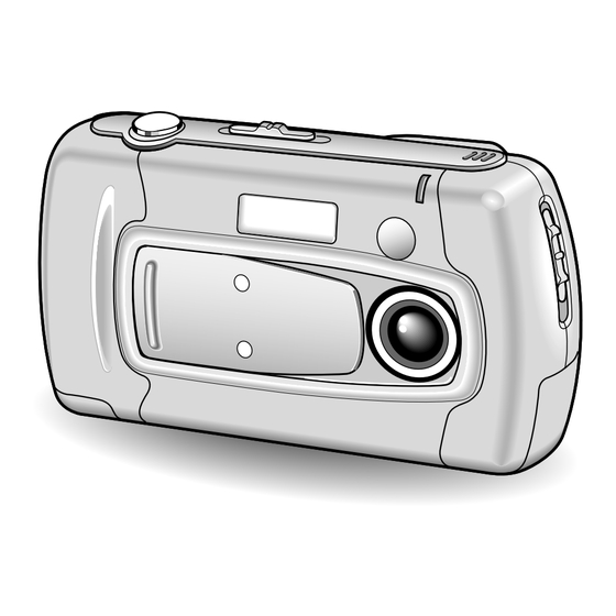
Color Digital Camera
Contents
1. OUTLINE OF CIRCUIT DESCRIPTION .................... 2
2. DISASSEMBLY ........................................................ 12
3. ELECTRICAL ADJUSTMENT .................................. 15
4. TROUBLESHOOTING GUIDE ................................. 20
5. PARTS LIST ............................................................. 21
CABINET AND CHASSIS PARTS 1 ........................ 21
CABINET AND CHASSIS PARTS 2 ........................ 22
ELECTRICAL PARTS .............................................. 23
ACCESSORIES ....................................................... 28
PACKING MATERIALS ............................................ 28
CIRCUIT DIAGRAM (Refer to the separate volume)
The components designated by a symbol ( ! ) in this schematic diagram designates components whose value are of
special significance to product safety. Should any component designated by a symbol need to be replaced, use only the part
designated in the Parts List. Do not deviate from the resistance, wattage, and voltage ratings shown.
CAUTION : Danger of explosion if battery is incorrectly replaced.
Replace only with the same or equivalent type recommended by the manufacturer.
Discard used batteries according to the manufacturer's instructions.
NOTE : 1. Parts order must contain model number, part number, and description.
2. Substitute parts may be supplied as the service parts.
3. N. S. P. : Not available as service parts.
Design and specification are subject to change without notice.
SR662/E, EX, U
PRODUCT SAFETY NOTICE
FILE NO.
VPC-X360E
(Product Code : 126 251 01)
(U.K.)
VPC-X360EX
(Product Code : 126 251 02)
(Europe)
(PAL General)
VPC-X360
(Product Code : 126 251 03)
(U.S.A.)
(Canada)
REFERENCE No. SM5310090
Advertisement
Table of Contents

Related Manuals for Sanyo VPC-X360E


Summary of Contents for Sanyo VPC-X360E
-
Page 1: Table Of Contents
FILE NO. SERVICE MANUAL Color Digital Camera VPC-X360E (Product Code : 126 251 01) (U.K.) VPC-X360EX (Product Code : 126 251 02) (Europe) (PAL General) VPC-X360 (Product Code : 126 251 03) (U.S.A.) (Canada) Contents 1. OUTLINE OF CIRCUIT DESCRIPTION ....2 2. -
Page 2: Outline Of Circuit Description
1. OUTLINE OF CIRCUIT DESCRIPTION 1-1. CA-1 CIRCUIT DESCRIPTION 1. IC Configuration [Features] IC903 (ICX204AK) CCD imager Independent storage and retrieval for each pixel IC902 (74VHC04MTC) H driver Square pixel unit cell IC904 (CXD1267AN) V driver XGA compatible IC905 (AD9802) CDS/AGC, A/D converter R, G, B primary color mosaic filter Continuous variable speed electronic shutter function... - Page 3 3. IC902 (H Driver) and IC904 (V Driver) 4. IC905 (CDS, AGC Circuit and A/D converter) An H driver (IC902) and V driver (IC904) are necessary in The video signal which is output from the CCD is input to order to generate the clocks (vertical transfer clock, horizon- Pins (26) and (27) of IC905.
- Page 4 5. Transfer of Electric Charge by the Horizontal CCD The transfer system for the horizontal CCD emplays a 2-phase drive method. The electric charges sent to the final stage of the horizontal CCD are transferred to the floating diffusion, as shown in Fig. 1-5. RG is turned on by the timing in (1), and the floating diffusion is charged to the potential of PD.
- Page 5 1-2. CA2 CIRCUIT DESCRIPTION 1. Circuit Description 1-7. 8-bit D/A circuit (Audio) 1-1. Scannning converter (Interlace converter) This circuit converts the audio signals (analog signals) from This circuit uses the function of a 64-Mbit SDRAMs to con- the microphone to 8-bit digital signals. vert the non-interlaced signal which is output from the CCD 1-8.
- Page 6 3. LCD Block During EE, gamma conversion is carried out for the 10-bit RGB data which is input from the A/D conversion block of the CCD to the ASIC in order that the revised can be displayed on the video. The YUV of 640 x 480 is then transferred to the SVRAM.
- Page 7 1-3. PW1 POWER CIRCUIT DESCRIPTION 1. Outline 3. Digital 3.3 V Power Output This is the main power circuit, and is comprised of the follow- 3.3 V (D) is output. Feedback for the 3.3 V (D) is provided to ing blocks. the switching controller (Pins (1) of IC501) so that PWM con- Switching controller (IC501) trol can be carried out.
- Page 8 1-4. PW1 STROBE CIRCUIT DESCRIPTION 1. Charging Circuit 2. Light Emission Circuit When UNREG power is supplied to the charge circuit and the When RDY and TRIG signals are input from the ASIC expan- CHG signal becomes High (3.3 V), the charging circuit starts sion port, the stroboscope emits light.
- Page 9 1-5. SY1 CIRCUIT DESCRIPTION 1. Configuration and Functions For the overall configuration of the SY1 circuit board, refer to the block diagram. The configuration of the SY1 circuit board centers around a 8-bit microprocessor (IC301). The 8-bit microprocessor handles the following functions. 1.
- Page 10 2. Internal Communication Bus The SY1 circuit board carries out overall control of camera operation by detecting the input from the keyboard and the condition of the camera circuits. The 8-bit microprocessor reads the signals from each sensor element as input data and outputs this data to the camera circuits (ASIC) or to the LCD display device as operation mode setting data.
- Page 11 4. Power Supply Control The 8-bit microprocessor controls the power supply for the overall system. The following is a description of how the power supply is turned on and off. When the battery is attached, a regulated 3.3 V voltage is normally input to the 8-bit microprocessor (IC301) by IC303, so that clock counting and key scanning is carried out even when the power switch is turned off, so that the camera can start up again.
-
Page 12: Disassembly
2. DISASSEMBLY 2-1. REMOVAL OF CABINET ASSEMBLY (FRONT) AND CABINET ASSEMBLY (BACK) 6. Screw 1.7 x 3 7. Cabinet top 3. Back cabinet 13. Holder battery 12. Five screws 1.7 x 3 1. Four screws 2. Front cabinet 1.7 x 4 10. - Page 13 2-3. REMOVAL OF LENS VF AND PW1 BOARD 1. Two screws 1.7 x 3 2. Lens VF 4. Connector 5. Connector 8. Reflector 3. Two screws 1.7 x 3 6. Three screws 1.7 x 3 7. Holder chassis PW1 9. PW1 board...
- Page 14 2-4. REMOVAL OF LCD, CA2 BOARD AND CA1 BOARD 8. Holder 9. CA2 board chassis 3. Four screws 7. Two 1.7 x 3 screws 1.7 x 3 6. Two connectors 2. LCD 4. Connector 11. Holder chassis 5. Screw 1.7 x 3 1.
-
Page 15: Electrical Adjustment
3. ELECTRICAL ADJUSTMENT 3-1. Table for Servicing Tools 3-4. Setup 1. System requirements Windows 95 or 98 Ref. No. Name Part code IBM R -compatible PC with 486 or higher processor Color viewer 5,100 K VJ8-0007 CD-ROM drive Siemens star chart 3.5-inch high-density diskette drive Calibration software VJ8-0166... - Page 16 3-5. Connecting the camera to the computer 1. Turn off both camera and computer. 2. Locate the port cover on the side of the camera. Press on the arrows and slide the cover down to open it. 3. Line up the arrow on the cable connector with the notch on the camera's serial port. Insert the connector. 4.
- Page 17 3. 3.3 V (D) Voltage Adjustment 3-6. Adjust Specifications CL533 or CL553 or CL519 Measuring Point [PW1 board (Side A/B)] Measuring Equipment Digital voltmeter ADJ. Location VR502 3.30 0.03 V ADJ. Value VR501 VR502 Adjustment method: 1.Adjust with VR502 to 3.30 0.03 V.
- Page 18 8. AWB Adjustment Preparation: POWER switch: ON Adjusting location: Flange-back adjustment screw (Fig. 1) Adjust the adjustment screw by turning it through the hole pro- vided in the CA1 board. If this adjustment screw is turned counter-clockwise, the focal length of the lens will decrease, and if it is turned clockwise, the focal length will increase.
- Page 19 adjustment LCD screen frame 10-2. LCD RGB Offset Adjustment CL424 waveform Adjusting method: 1. Adjust LCD “RGB offset” so that the amplitude of the CL424 waveform is 7.5 Vp-p 0.3 V. 0.2 V 7.5 Vp-p 0.3 V CL426 waveform 10-5. LCD Red Brightness Adjustment Adjusting method: CL424 waveform 1.
-
Page 20: Troubleshooting Guide
4. TROUBLESHOOTING GUIDE TAKING INOPERATIVE POWER LOSS INOPERTIVE CLOSE PUSH SHUTTER NORMAL BARRIER SW BARRIER SW ON BUTTON OPEN IC301-4, 5 CHECK HIGH CHECK S6002, (SCAN IN 0, 1) S3029, D3064, IC301-4, 93 CN302, D3069, R3021 PULSE INPUT R3021, R3022 IC301-70, 71 IC302-7 (UP UNREG) CHECK IC301... -
Page 21: Parts List
5 . PARTS LIST LOCATION PARTS NO. DESCRIPTION LOCATION PARTS NO. DESCRIPTION 636 055 5853 HOLDER TERMINAL-SR662/J CABINET & CHASSIS PARTS 1 636 056 0956 DEC MONITOR-SR662/E 636 056 2479 ASSY,COVER LENS-SR662/E 636 055 9080 ASSY,CABINET BACK-SR662/J 636 055 5600 COVER FRONT-SR662/J 636 055 5938 KNOB POWER-SR662/J... -
Page 22: Cabinet And Chassis Parts 2
LOCATION PARTS NO. DESCRIPTION LOCATION PARTS NO. DESCRIPTION 636 055 4276 COMPL PWB,CA-2,EXCEPT VPC-X360 CABINET & CHASSIS PARTS 2 636 056 6705 COMPL PWB,CA-2,VPC-X360 ONLY 645 029 2170 LENS(ASSY) 636 055 4290 COMPL PWB,PW-1 645 032 5854 OPTICAL FILTER 636 055 5822 HOLDER CHASSIS PW1-662/J 636 052 2183 SPACER... -
Page 23: Electrical Parts
ELECTRICAL PARTS Note: 1. Materials of Capacitors and Resistors are abbreviated as follows ; Resistors Capacitors MT-FILM Metallized Film Resistor MT-POLYEST Metallized Polyester Capacitor MT-GLAZE Metallized Glaze Resistor MT-COMPO Metallized Composite Capacitor OXIDE-MT Oxide Metallized Film Resistor TA-SOLD Tantalum Solid Capacitor AL-SOLID Aluminum Solid Capacitor NP-ELECT... - Page 24 LOCATION PARTS NO. DESCRIPTION LOCATION PARTS NO. DESCRIPTION C9022 403 312 6805 CERAMIC 0.1U Z 16V R9019 401 225 2006 MT-GLAZE 680 JA 1/16W C9023 403 320 5302 CERAMIC 0.15U K 25V R9020 401 224 8900 MT-GLAZE 100K JA 1/16W C9025 403 312 6805 CERAMIC...
- Page 25 LOCATION PARTS NO. DESCRIPTION LOCATION PARTS NO. DESCRIPTION X1101 645 024 0461 OSC,CRYSTAL 17.734476MHZ, R1014 401 225 7902 MT-GLAZE 220 JA 1/16W EXCEPT VPC-X360 R1015 401 225 0309 MT-GLAZE 33 JA 1/16W (INDUCTORS) R1016 401 225 0309 MT-GLAZE 33 JA 1/16W L1101 645 016 0363 INDUCTOR,600 OHM...
- Page 26 LOCATION PARTS NO. DESCRIPTION LOCATION PARTS NO. DESCRIPTION (SWITCH) D5407 407 151 4701 DIODE 1SS301-(TE85L) S1001 645 023 0844 SWITCH,PUSH 1P-1TX1, 407 130 4401 DIODE DAN202U (CONNECTORS) 407 134 7408 DIODE MA141WK CN101 645 036 7489 SOCKET,PWB-PWB 40(N.S.P) 407 106 1601 DEODE DCG015 CN102 645 030 6655...
- Page 27 LOCATION PARTS NO. DESCRIPTION LOCATION PARTS NO. DESCRIPTION C5058 403 345 3109 POS-SOLID 33U M 10V R5074 401 258 9300 MT-GLAZE 220K DC 1/16W C5059 403 345 3000 POS-SOLID 47U M 6.3V R5075 401 258 0406 MT-GLAZE 120K DC 1/16W C5061 403 335 1405 CERAMIC...
-
Page 28: Accessories
401 224 9303 MT-GLAZE 1K JA 1/16W R3021 401 224 9006 MT-GLAZE 10K JA 1/16W 636 056 2127 CARTON CASE INNER-662/E,VPC-X360E ONLY R3022 401 224 9907 MT-GLAZE 22K JA 1/16W 636 056 2134 CARTON CASE INNER-662/EX, R3023 401 224 9006...
Need help?
Do you have a question about the VPC-X360E and is the answer not in the manual?
Questions and answers