Table of Contents
Advertisement
Quick Links
Advertisement
Table of Contents

Related Manuals for Kenwood KAC-M615D


Summary of Contents for Kenwood KAC-M615D
- Page 1 CLASS D MONO POWER AMPLIFIER KAC-M615D INSTRUCTION MANUAL © B64-4193-00/00 (MV)
-
Page 2: Safety Precautions
• To prevent a short circuit, never put or leave any • For the power cord and ground, use a vehicle type metallic objects (such as coins or metal tools) inside (fireproof ) power wring cord with a current capacity the unit. greater than the unit’s fuse capacity. (Use a power wiring cord with a diameter of 5 mm2 (AWG 10) or • If the unit starts to emit smoke or strange smells, greater.) turn off the power immediately and consult your Kenwood dealer. • When more than one power amplifier are going to be used, use a power supply wiring wire and • Do not touch the unit during use because the protective fuse of greater current-handling capacity surface of the unit becomes hot and may cause than the total maximum current drawn by each burns if touched. amplifier. • Mounting and wiring this product requires skills and experience. For safety’s sake, leave the mounting and wiring work to professionals. Speaker selection • The input power of the speakers that are going to CAUTION be connected should be greater than the output power (in Watts) of the amplifier. Use of speakers... - Page 3 Installation 198 mm 131 mm Self-tapping screw (ø4 × 16 mm) Installation board, etc. (thickness : 15 mm or more) English...
-
Page 4: Installation Procedure
Installation Accessories harness, and be careful not to cause scratches or other damage. Number • Do not install near the dashboard, rear tray, or air Part name External View of Items bag safety parts. Self-tapping screws • The installation to the vehicle should securely (ø4 × 16 mm) fasten the unit to a place in which it will not Terminal cover obstruct driving. If the unit comes off due to a (Power terminal) shock and hits a person or safety part, it may cause injury or an accident. Speaker level input cable • After installing the unit, check to make sure that electrical equipment such as the brake lamps, turn signal lamps and windshield wipers operate normally. Installation procedure Since there are large variety of settings and connections possible according to applications, read Protection function the instruction manual well to select the proper The protection function is activated in the following setting and connection. situations: 1. R emove the ignition key and disconnect the This unit is equipped with a protection function for negative · terminal of the battery to prevent short... - Page 5 Connection WARNING Remove the ignition key and disconnect the negative · terminal of the battery to prevent short circuits. CAUTION • If sound is not output normally, immediately turn power off and check connections. • Be sure to turn the power off before changing the setting of any switch. • If the fuse blows, check wires for shorts, then replace the fuse with one of the same rating. • Check that no unconnected wires or connectors are touching the car body. Do not remove caps from unconnected wires or connectors to prevent short circuits. • Connect the speaker wires to appropriate speaker connectors separately. Sharing the negative wire of the speaker or grounding speaker wires to the metal body of the car can cause this unit to fail. NOTE • Do not connect cables and leads to both RCA cable input jacks and the speaker level input terminals simultaneously, for this may cause malfunction or damage. Speaker level input connections • The genuine-accessory car stereo shall have a maximum power output of no more than 40 W.
- Page 6 Connection * Commercially available parts ■ RCA cable or Speaker level input connection • RCA cable connections Left input Right input INPUT FREQUENCY[Hz] SENSITIVITY[V] LINE IN SPEAKER LEVEL INPUT [MIN] [MAX] BASS EXPANDER RCA cable* CENTER UNIT (CD receiver, etc.) Power control wire* • Speaker level input connections Cable Color of the connector 9 White INPUT FREQUENCY[Hz]...
-
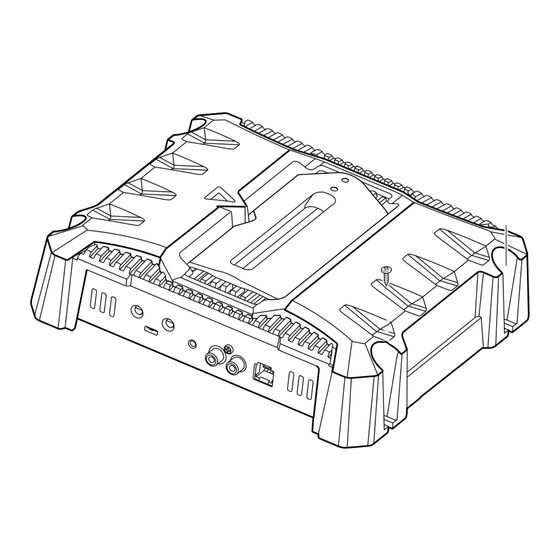
Page 7: Power Indicator
Controls 40W–15W INPUT FREQUENCY[Hz] SENSITIVITY[V] LINE IN SPEAKER LEVEL INPUT [MAX] [MIN] [ MAX ] [ MIN ] BASS EXPANDER 1 Power indicator When the power is turned on, the Power indicator lights. If the Power indicator does not light when the power is turned on, the protection function may be activated. Check whether there is any indication of trouble. Refer to <Protection function> (page 4). 2 LPF(Low-Pass Filter) FREQUENCY control This control adjusts the frequency band output from this unit. 3 BASS EXPANDER switch Setting this switch to "ON", when a certain volume is exceeded, a dynamic bass sound is output. 4 INPUT SENSITIVITY control Set this control according to the pre-output level of the center unit connected with this unit, or to the maximum power output of the genuine-accessory car stereo. -
Page 8: Troubleshooting Guide
Troubleshooting Guide What might appear to be a malfunction in your unit may just be the result of slight misoperation or miswiring. Before calling service, first check the following table for possible problems. No sound. (Blown fuse.) Input (or output) cables are disconnected. Connect the input (or output) cables. ...
Need help?
Do you have a question about the KAC-M615D and is the answer not in the manual?
Questions and answers