
Related Manuals for Northern N-1000-III

Summary of Contents for Northern N-1000-III
- Page 1 N-1000-III/IV Installation and Programming Manual TD1064 rev0400 - NCI ADEMCO Part # K4788...
- Page 2 United States. Notice: Any use of this product is subject to the terms and acceptance of the Northern Computers, Inc. “Software Agreement.” Please request a copy from Northern Computers, Inc. and review this agreement carefully.
- Page 3 N-1000-III/IV i i i i i i i i i i...
-
Page 4: Table Of Contents
Contents Contents Contents Contents UL Note......................vi New and Improved Features of the N-1000-III/IV ..........vii Section 1: Introduction/Access Control ............. 1-1 Section 2: System Overview ................2-1 2-1: N-1000-III/IV ............................2-1 2-2: Programming Devices ..........................2-2 2-3: C-100-A1 Converter ........................... 2-4 2-4: N-485-PCI-2 or HUB-2 .......................... - Page 5 O Command ............................A-17 P Command ............................A-18 R Command ............................A-18 T Command ............................A-19 V Command ............................A-19 W Command (Used with the N-1000-III/IV only) ..................A-20 Z Command ............................A-21 OR’ing of Inputs .............................A-21 Output Groups by Readers ..........................A-22 Appendix B: N-1000-III/IV Compared to N-1000-II......... B-1 Appendix C: Troubleshooting ................
- Page 6 The N-1000-III/IV Installation Manual provides all information necessary for installation of N-1000-III, N-1000-III-X, N-1000-IV , and N-1000-IV-X control panels. All of the N-1000-III/IV versions have both the 20 mA and 485 multi-drop commu- nications interfaces. The N-1000-III/IV can be used in existing N-1000-II/N-800 systems provided the existing panels have version 8.0 or higher firmware.
-
Page 7: Ul Note
UL Note The N-1000-III/IV panel’s alarm point monitoring only monitors the door position (UL294). It is not intended as a proprietary burglar alarm (UL1094). The control panel was UL294 tested as a stand alone unit only. -
Page 8: New And Improved Features Of The N-1000-Iii/Iv
New and Improved Features of the N-1000-III/IV The N-1000-III/IV series panels have both a number of improvements and some unique features as compared to the N-1000-II control panels. Some of these features are highlighted below. For a more detailed description refer to Appendix B of this manual. - Page 9 N-1000-III/IV viii viii viii viii viii • Detection of a primary power failure by either the internal sensor or the input from the relay on the external supply will generate an Alarm 19 not Alarm 8. Alarm Point 8 is now available for use as a standard alarm point •...
-
Page 10: Section 1: Introduction/Access Control
Section 1: Access Control Section 1: Access Control Section 1: Access Control Section 1: Access Control Section 1: Access Control N-1000-III/IV 1–1 INTRODUCTION Section 1: Access Control Access control is computerized control over entry to any area that can be secured with a lock and key. - Page 11 1–2 N-1000-III/IV Section 1: Access Control Section 1: Access Control Section 1: Access Control Section 1: Access Control Section 1: Access Control...
-
Page 12: Section 2: System Overview
Figure 2-1, while Figure 2-2 illustrates a typical 485 multi-drop configuration. The N-1000-III control panel provides 16 points for alarm monitoring and four output control relays. The N-1000-III-X control panel includes four additional relays (providing a total of eight) and has expanded database/buffer memory capacity. -
Page 13: 2-2: Programming Devices
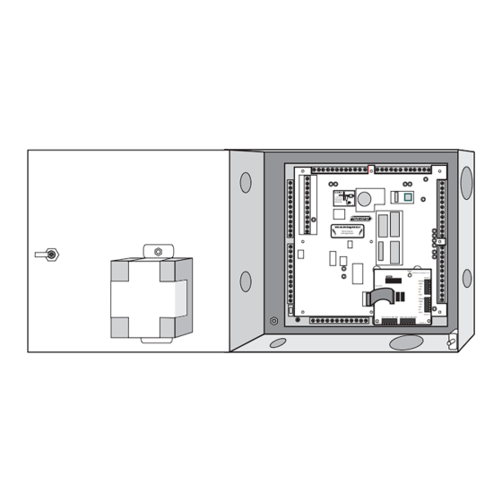
Section 2: System Overview Section 2: System Overview N-1000-III-X is shown in Figure 2-3 with enclosure and battery. Figure 2-4 shows the N-1000-IV-X with Four Reader Board, battery and enclosure. The minimum configuration for the N-1000-III/IV includes the control panel, power transformer, reader and communication converter. - Page 14 Figure 2-3. N-1000-III-X Panel with Enclosure. The N-1000-III control panel provides 16 alarm points for alarm monitoring capability and four relays for output control capability. The N-1000-III-X includes four additional relays (providing a total of eight) and has expanded database/buffer memory capacity.
-
Page 15: 2-3: C-100-A1 Converter
N-1000-III/IV . 2-5: PROM Versions The N-1000-III/IV PROM (Programmable Read Only Memory) chips provide permanent storage for the program and control logic information necessary to coordinate and drive the system hardware. The PROM chip is also referred to as the control panel’s FIRMWARE. -
Page 16: Section 3: Hardware Specifications
3–1 Section 3: Hardware Specifications Power Requirements: The N-1000-III/IV requires a 16.5 VAC, 50 VA, 60 HZ or 12 VDC linear (2 amp continuous) power supply. Output Power: 12 VDC (10 to 14 volts) 500 mA for readers requiring 12 VDC or motion detector devices (not for use with locking devices). - Page 17 LED D1 DØ +5v GND Shield LED D1 DØ +5v GND Shield Reader 1 Reader 2 Figure 3-1. Enclosure for the N-1000-III/IV . The N-1000 enclosure, shown here with the N-1000-IV panel, has a lock and key, knockouts and a tamper switch. A 12 VDC battery is mounted on the door.
-
Page 18: Section 4: Installation/Panel Layout
INSTALLATION Section 4: Panel Layout The N-1000-III-X has nine screw-down terminal blocks. Each terminal block, in turn, has 12 individual terminal positions, described in the following sections. Figure 4-1 shows the panel with its printed template. The N-1000-IV-X has an additional board in place of TB5 (see Figure 4-2) with four removable wiring terminal blocks for connection to four readers. -
Page 19: 4-1: Four Reader Board (N-1000-Iv Only)
4–2 4–2 4–2 4–2 4–2 N-1000-III/IV N-1000-III/IV N-1000-III/IV N-1000-III/IV N-1000-III/IV Section 4: P Section 4: P Section 4: P Section 4: P Section 4: Panel L anel L anel L anel L anel Layout ayout ayout ayout ayout 4-1: Four Reader Board (N-1000-IV only) The N-1000-IV supports up to four card readers. - Page 20 Shorting these prongs (labeled TEST) will cause the board to generate a simulated card read (with the PIC firmware version ) from each of the four readers. Status LED Northern Computers, Inc. Shield Cable Drain Wire Reader 4 Ground...
-
Page 21: 4-2: Terminal Blocks 1, 2, 3, 4
Each DPDT relay provides control for up to two external devices. Both poles of a given relay have a normally-closed terminal, a common terminal and a normally- open terminal. (See Figure 4-4.) Northern recommends using the A pole of the relays for locks (inductive loads) and the B pole for dry circuit (logic) applica- tion. - Page 22 Panel must be 6 NC earth grounded. 7 NO 8 COM 9 NC 10 NO 11 COM 12 NC Figure 4-4. Terminal Blocks 1, 2, 3, 4. Terminal blocks 3 and 4 are available on the X versions of the N-1000-III/IV.
-
Page 23: 4-3: Terminal Block 5
4-3: Terminal Block 5 Terminal Block 5 (N-1000-III only) supports the interface to two Wiegand output card readers and provides an alarm point common. Each card reader port includes terminals for LED control, Data 1 signal, Data Ø signal, +5 VDC output and Ground. - Page 24 Figure 4-5. Terminal Block 5 and Terminal Block 6. Terminal Block 5 is only available on the N-1000-III. It supports the interface to two Wiegand output card readers and provides an alarm point common. Terminal Block 6 contains alarm input points 5-16 terminals. Any N-1000...
-
Page 25: 4-5: Terminal Block 7
4–8 4–8 4–8 4–8 4–8 N-1000-III/IV N-1000-III/IV N-1000-III/IV N-1000-III/IV N-1000-III/IV Section 4: P Section 4: P Section 4: P Section 4: P Section 4: Panel L anel L anel L anel L anel Layout ayout ayout ayout ayout 4-5: Terminal Block 7... - Page 26 Section 4: P Section 4: Panel L anel L anel L anel L anel Layout ayout ayout ayout ayout N-1000-III/IV N-1000-III/IV N-1000-III/IV N-1000-III/IV N-1000-III/IV 4–9 4–9 4–9 4–9 4–9 Figure 4-6. Terminal Block 7. Terminal Block 7 contains the 485 multi-drop communication connection terminals for alarm input points 1 through 4, an alarm point common and the 20 mA communication loop (receive and transmit) terminals.
-
Page 27: 4-6: Terminal Block 8
See Figure 4-7. The 12 volt back-up battery wires are soldered to the circuit board. When connecting an external DC supply the N-1000-III/IV 12 VDC battery can remain connected and provides additional battery backup. TB9 Terminal... - Page 28 Section 4: P Section 4: Panel L anel L anel L anel L anel Layout ayout ayout ayout ayout N-1000-III/IV N-1000-III/IV N-1000-III/IV N-1000-III/IV N-1000-III/IV 4–11 4–11 4–11 4–11 4–11 Figure 4-7. Terminal Blocks 8 & 9. Terminal Block 8 is used for 11-conductor matrix keypad connections and also provides an alarm point common.
-
Page 29: 4-8: Dip Switch Settings
4-8: DIP Switch Settings N-1000-III/IV DIP switch positions 1 and 2 control the panel baud rate for the 20 mA Loop. Set the panel baud rate to match that of the system programming device. 1200 baud is recommended for computer and data terminal systems. For 485 communications use the 4800 baud setting. - Page 30 For DIP switches with OPEN/CLOSED notation: OPEN=Off CLOSED=On The restart button MUST be pressed to activate a change made to any NOTE: DIP switch setting (for baud rate and/or panel address). Pressing the restart button DOES NOT alter N-1000-III/IV database memory.
-
Page 31: 4-9: Jumpers
4–14 4–14 4–14 4–14 4–14 N-1000-III/IV N-1000-III/IV N-1000-III/IV N-1000-III/IV N-1000-III/IV Section 4: P Section 4: P Section 4: P Section 4: P Section 4: Panel L anel L anel L anel L anel Layout ayout ayout ayout ayout 4-9: Jumpers... -
Page 32: 4-10: Connectors
Jumpers 5, 7, 8, and Rev. A Connector 11 are not used. Figure 4-9. Configuration Jumpers and Connectors. The N-1000-III/IV panels provide for either 485 multi-drop communication or 20 mA communication loops. These modes are selected by changing jumper settings. -
Page 33: 4-11: Leds
4-11: LEDs The functions of the N-1000-III/IV LEDs are listed below and also illustrated in Figure 4-10. When an LED is lit it indicates that its relay is energized, that is the normally open relay contacts become closed and the normally closed relay contacts become open. - Page 34 Section 4: P Section 4: Panel L anel L anel L anel L anel Layout ayout ayout ayout ayout N-1000-III/IV N-1000-III/IV N-1000-III/IV N-1000-III/IV N-1000-III/IV 4–17 4–17 4–17 4–17 4–17 Figure 4-10. LED Functions. When an LED is lit it indicates that its relay is energized, that is, the normally open relay contacts become closed and the normally closed relay contacts become open.
-
Page 35: 4-12: Restart Button
4-13: RAM Chip Control panel RAM chips store all database and transaction buffer memory. The N-1000-III/IV control panels use a single RAM chip with the option of an addi- tional chip in socket U6. The N-1000-III/IV-X control panels come equipped with an extra RAM chip. - Page 36 N-1000-III/IV microprocessor. It can be used to restart a “locked-up” control panel or to activate a change made to any DIP switch setting (for baud rate and/or panel address). The N-1000-III/ IV-X control panel comes equipped with an additional RAM chip, located in socket U6. The control panel PROM chips, located in sockets U5 &...
- Page 37 Card Reader Switch Switch Figure 4-12. Example Wiring Diagram. Card Readers connect to TB5 of the N-1000-III as shown here. On the N-1000-IV, the card readers connect to the Four Reader Board. Refer to Section 4-3 for typical wiring diagram.
-
Page 38: Section 5: Operation
5-1: Card Reader/Keypad Operation Some card readers require that a format (software) command be programmed into the host N-1000-III/IV controller before cards can be read. If the format command is not programmed into the control panel, these readers or keypads will not trans- mit card numbers to the terminal/printer. - Page 39 5–2 5–2 5–2 5–2 5–2 N-1000-III/IV N-1000-III/IV N-1000-III/IV N-1000-III/IV N-1000-III/IV Section 5: Operation Section 5: Operation Section 5: Operation Section 5: Operation Section 5: Operation Door 1 Door Status Switch Door 2 Door Status Switch N-1000-IV Door Status Switch Door 1...
- Page 40 DEVICE (CONNECT DEVICE (CONNECT WITHIN 18 INCHES). WITHIN 18 INCHES). Panel must be Panel must be earth grounded. earth grounded. Status Status Northern Computers, Inc. Northern Computers, Inc. Reader 4 Reader 4 Shield Shield To N-1000 To N-1000 DØ DØ...
-
Page 41: 5-2: Alarm Input Points
5-2: Alarm Input Points All N-1000 alarm input points default to normally-closed, non-supervised circuits used to monitor changes of state. N-1000-III/IV inputs can also be configured for normally-open circuits and 3-state supervised circuits. Input points have both a physical state and a software state, as described below: Physical State Input points have physical states of OPEN and CLOSED. -
Page 42: 5-3: Relay Output Points
The time zone parameter defines the time the input point is automatically shunted (deactivated). 5-3: Relay Output Points All N-1000-III/IV relay output points have both normally-open and normally- closed contacts, used to switch (activate/deactivate) electrical devices. Output points have only a physical state, as described below: Physical State Output points have physical states of DE-ENERGIZED and ENERGIZED. -
Page 43: 5-4: Default Input Point/Output Point Interaction
5–6 5–6 5–6 5–6 5–6 N-1000-III/IV N-1000-III/IV N-1000-III/IV N-1000-III/IV N-1000-III/IV Section 5: Operation Section 5: Operation Section 5: Operation Section 5: Operation Section 5: Operation Time Zone The time zone parameter defines the time the output is automatically energized. Outputs 11 & 12 control Card Reader 1 and Card Reader 2 LEDs, respectively. On the N-1000-IV panel, outputs 13 &... - Page 44 Door Status Switch Door 2 Lock Solenoid Shunt Time = 15 sec. Output (LED) Pulse Time = 2 sec. Status Status Northern Computers, Inc. Northern Computers, Inc. Reader 4 Reader 4 Shield Shield To N-1000 To N-1000 DØ DØ Shield Shield Door Status DØ...
- Page 45 5–8 5–8 5–8 5–8 5–8 N-1000-III/IV N-1000-III/IV N-1000-III/IV N-1000-III/IV N-1000-III/IV Section 5: Operation Section 5: Operation Section 5: Operation Section 5: Operation Section 5: Operation Configurations WITH Anti-Passback: Input Point Reserved for: Shunt Time Input 1 Door position switch for Door 1...
- Page 46 Section 5: Operation Section 5: Operation Section 5: Operation Section 5: Operation Section 5: Operation N-1000-III/IV N-1000-III/IV N-1000-III/IV N-1000-III/IV N-1000-III/IV 5–9 5–9 5–9 5–9 5–9 Output Point (relay) 1 Pulse Time = 10 seconds Door Door 1 Status Switch Door Status Switch...
- Page 47 5–10 5–10 5–10 5–10 5–10 N-1000-III/IV N-1000-III/IV N-1000-III/IV N-1000-III/IV N-1000-III/IV Section 5: Operation Section 5: Operation Section 5: Operation Section 5: Operation Section 5: Operation Egress (exit) Device (Input Point 5) Door 1 Shunt Time = 0 Door Status Switch...
- Page 48 Section 5: Operation Section 5: Operation Section 5: Operation Section 5: Operation Section 5: Operation N-1000-III/IV N-1000-III/IV N-1000-III/IV N-1000-III/IV N-1000-III/IV 5–11 5–11 5–11 5–11 5–11 Egress (exit) device (Input Point 6) Door 2 Shunt Time = 0 Door Status Switch...
- Page 49 DEVICE (CONNECT WITHIN 18 INCHES). WITHIN 18 INCHES). Panel must be Panel must be earth grounded. earth grounded. Input 3 Status Status LED Northern Computers, Inc. Northern Computers, Inc. Reader 4 Reader 4 Shield Shield To N-1000 To N-1000 DØ DØ...
- Page 50 DEVICE (CONNECT WITHIN 18 INCHES). WITHIN 18 INCHES). Panel must be Panel must be earth grounded. earth grounded. Input 4 Status Status LED Northern Computers, Inc. Northern Computers, Inc. Reader 4 Reader 4 Shield Shield To N-1000 To N-1000 DØ DØ...
-
Page 51: 5-5: Auto-Relock Operation
5–14 5–14 5–14 5–14 5–14 N-1000-III/IV N-1000-III/IV N-1000-III/IV N-1000-III/IV N-1000-III/IV Section 5: Operation Section 5: Operation Section 5: Operation Section 5: Operation Section 5: Operation 5-5: Auto-Relock Operation The auto-relock feature results in the immediate re-locking and re-arming (unshunting) of a door when the door status switch is closed after entry. With... - Page 52 Section 5: Operation Section 5: Operation Section 5: Operation Section 5: Operation Section 5: Operation N-1000-III/IV N-1000-III/IV N-1000-III/IV N-1000-III/IV N-1000-III/IV 5–15 5–15 5–15 5–15 5–15 Door Status Device (Input Point 1) Shunt Time = 15 seconds Door 1 N-1000-III WARNING!
- Page 53 5–16 5–16 5–16 5–16 5–16 N-1000-III/IV N-1000-III/IV N-1000-III/IV N-1000-III/IV N-1000-III/IV Section 5: Operation Section 5: Operation Section 5: Operation Section 5: Operation Section 5: Operation Egress (exit) Device (Input Point 6) Shunt Time = 0 Door 2 Door Status Device...
- Page 54 Section 5: Operation Section 5: Operation Section 5: Operation Section 5: Operation Section 5: Operation N-1000-III/IV N-1000-III/IV N-1000-III/IV N-1000-III/IV N-1000-III/IV 5–17 5–17 5–17 5–17 5–17 Egress (Exit) Device (Input Point 8) Shunt Time = 0 Door 4 Door Status Device...
- Page 55 5–18 5–18 5–18 5–18 5–18 N-1000-III/IV N-1000-III/IV N-1000-III/IV N-1000-III/IV N-1000-III/IV Section 5: Operation Section 5: Operation Section 5: Operation Section 5: Operation Section 5: Operation...
-
Page 56: Section 6: Wiring Requirements
6-1: Card Readers Some card readers require that a format (software) command be programmed into the host N-1000-III/IV controller before cards can be read. When a card is run through a card reader that requires a format command, but the format command has not been programmed into the control panel, no card number is transmitted to the terminal/printer. - Page 57 Card Reader 1 Card Reader 2 Figure 6-1. Card Reader Connections to TB5. N-1000-III Terminal Block 5 supports interface for two Wiegand output card readers and provides an alarm point common. Each card reader port includes terminals for LED control, Data 1 signal, Data Ø signal, +5 VDC output and Ground.
-
Page 58: 6-2: Four Reader Board (N-1000-Iv Only)
– Not used Blue *+12 VDC power is available on Terminal Block 9 terminal 7. Use connection 4 or TB9 terminal 7 NOT BOTH. Status LED Northern Computers, Inc. Shield Cable Drain Wire Reader 4 Ground Black Shield + 5 VDC To N-1000 Data Ø... - Page 59 Four Card Reader wiring blocks. The shield at the card reader/keypad end should not be grounded unless the device is electrically floating (not touching metal). (See Figure 6-3.) Status LED Northern Computers, Inc. Shield Shield Reader 4...
-
Page 60: 6-3: Eleven Conductor Keypads
Section 6: Wiring Requirements Section 6: Wiring Requirements Section 6: Wiring Requirements N-1000-III/IV 6-3: Eleven Conductor Keypads A typical Eleven Conductor Keypad uses a 2 of 7 matrix configuration where each keypad row and column corresponds to a unique wire (Figure 6-4). When a key is pressed, two of seven wires are activated (two of the wires are put to ground);... - Page 61 N-1000-III/IV grounding point (float shield at keypad). If the keypad is mounted on ungrounded metal or nonmetallic material, tie the tan wire to the keypad cable’s shield only and connect the shield to the N-1000-III/IV ground point. 1 Brown...
-
Page 62: 6-4: Alarm Input Points
This enables the output device to be located up to 2000 feet (620 m) away from the N-1000-III/IV . An 18 gauge wire’s resistance results in a 6.5 volt drop for a quarter ampere load at 2000 feet. -
Page 63: 6-6-3: Aep-3 To N-1000-Iii/Iv
6-6-3: AEP-3 to N-1000-III/IV Up to two AEP-3 Relay Expansion Boards per N-1000-III/IV panel can be added to the communication loop. Using the cable supplied with the unit, one AEP-3 connects to the N-1000-III/IV at J1, and then to the next AEP-3. - Page 64 NC1821 cables must be set to the 20 mA Maximum distance: 2000' (610 m) (default) position 1 and 2. C-100-A1 C-100 to N-1000-III/IV: Last Controller to C-100: two, NC1821 cables two, NC1821 cables Maximum distance: 2000' (610 m) Maximum distance: 2000' (610 m)
- Page 65 6-10 6-10 6-10 6-10 6-10 N-1000-III/IV Section 6: Wiring Requirements Section 6: Wiring Requirements Section 6: Wiring Requirements Section 6: Wiring Requirements Section 6: Wiring Requirements S-4 SUPPRESSION REQUIRED ACROSS Lock Solenoid EVERY ACTIVE RELAY AND ELECTRICAL DEVICE (CONNECT WITHIN 18 INCHES).
- Page 66 Figure 6-10. Connecting an AEP-3 Relay Expansion Board. The AEP-3 Relay Expansion Board is shipped with a cable. It connects to the N-1000-III/IV panel at J1. The next AEP-3 Expansion Board connects to the first as shown above. See the AEP-3 manual for further details.
-
Page 67: Pc To N-485-Pci-2
Figure 6-11. Typical N-485 Multi-drop Configuration. This is a typical configuration with an N-485-PCI-2 at one end of the line and a panel at the other end. The AEP-3 is connected to the N-1000-III/IV at J1. See Figure 6-10 for details of the AEP-3 connection. -
Page 68: 6-6-6: N-485-Hub-2 To Panel
Note: When mixing N-1000-II panels witú the Núú000-IIúúIV in úú N- 485údropline, the N-485-API-2 panels must have the same version (1.xx, 2.xx...) as the N-1000-III/IV panel’s 485 EPROM. The dropline must be terminated at the ends. No other termination should be used at the panels which are not located at the ends. -
Page 69: 6-6-8: Bias And Eol With 485 Communication
The N-1000-III/IV can provide bias for the PCI, HUB and API units when they are not at the end of the line. Bias and EOL resistors on the N-1000-III/IV are attached by using the proper jumper settings. Setting JP2 and JP3 on provides both bias and EOL, while setting JP4 on provides EOL only. - Page 70 Section 6: Wiring Requirements Section 6: Wiring Requirements Section 6: Wiring Requirements Section 6: Wiring Requirements Section 6: Wiring Requirements N-1000-III/IV 6-15 6-15 6-15 6-15 6-15 Green/White Connected–EOL, bias PCI-2 Personal Computer running NCI software JP2 & 3 OFF–no bias, no EOL JP2 &...
- Page 71 From the N-485-PCI-2 to the N-1000-III/IV P P anel must be anel must be earth grounded. th grounded. and from the N-1000-III/IV to the N-1000-III/IV use twisted 24 gauge NC2021-GY-A or NCP2021-WH-A overall shielded cable with a characteristic impedance of 120 ohm and a capacitance Both of 20 pf./ft.
- Page 72 Section 6: Wiring Requirements Section 6: Wiring Requirements Section 6: Wiring Requirements Section 6: Wiring Requirements Section 6: Wiring Requirements N-1000-III/IV 6-17 6-17 6-17 6-17 6-17 Figure 6-15. 485 Multi-drop Connection with N485DRLA. The N-485-DRLA Digital Redundant Loop Adapter provides an alternate communications route in the event that wiring is cut or a short circuit.
-
Page 73: 6-7: Cable Specifications
Alarm input points NC1821-GR twisted pair, shielded 2000' (610 m) NC 2221-BR Relay outputs NC 1821-GR twisted pair, shielded 2000' (610 m) NC 2221-BR 2 conductor Note: for Plenum rated cable just add a “P” to Northern’s part number prefix... -
Page 74: 6-8: Nci Cable Part Numbers
Section 6: Wiring Requirements Section 6: Wiring Requirements Section 6: Wiring Requirements Section 6: Wiring Requirements Section 6: Wiring Requirements N-1000-III/IV 6-19 6-19 6-19 6-19 6-19 6-8: NCI Cable Part Numbers Part Number Description Application Length NC1821-GR 18 AWG/2 conductor... -
Page 75: 6-9: Configurations For Rs-232 Serial Communication Ports
6-20 6-20 6-20 6-20 6-20 N-1000-III/IV Section 6: Wiring Requirements Section 6: Wiring Requirements Section 6: Wiring Requirements Section 6: Wiring Requirements Section 6: Wiring Requirements 6-9: Configurations for RS-232 Serial Communication Ports PC’s, DigiBoard PC’s, DigiBoard WIN-EXP WIN-EXP WIN-EXP-8 or 16... -
Page 76: Section 7: Locks And Suppression
The lock wiring should be at least 12 inches away from the data lines, or it should have a separate conduit. DO NOT power door locks with the same power supply used for the N-1000-III/IV or card readers. - Page 77 7–2 N-1000-III/IV N-1000-III/IV N-1000-III/IV N-1000-III/IV N-1000-III/IV Section 7: Locks and Suppression...
-
Page 78: Section 8: Grounding
8–1 8–1 Section 8: Grounding It is important to ground all N-1000-III/IV control panels properly. Each panel in the communication loop should be individually grounded. In some locations, the individual earth ground is not adequate and a separate 12-14 gauge Common Ground wire should be run along with the communication loop wire. - Page 79 8–2 8–2 8–2 8–2 8–2 N-1000-III/IV N-1000-III/IV Section 8: Grounding Section 8: Grounding Section 8: Grounding Section 8: Grounding Section 8: Grounding Use one or the other, DO NOT USE BOTH TB9-1 and the “local” chassis ground. The chassis earth ground is preferred.
-
Page 80: Section 9: Power
9–1 Section 9: Power The N-1000-III/IV requires a 16.5 VAC, 50 VA, 60 HZ or a 12 VDC linear (2 Amp continuous) primary power supply. If using an AC power source as primary power supply, connect the primary power supply to TB9 positions 4 and 5, without regard to polarity. - Page 81 Upon loss of backup battery power, the control panel ceases operation, but retains database/transaction buffer memory for up to 7 days. Power-up Sequence for the N-1000-III/IV: Step 1: Set DIP-switch and verify jumper settings. Step 2: Make primary power supply connections.
-
Page 82: Appendix A: Programming Quick Reference Guide
N-1000-II and N-1000-III/IV control panels. For complete explanations and examples, contact the factory. Note: If the N-1000-II or the N-1000-III/IV is to be used in an existing N-1000-II system, the N-1000-II must be at least version 7.0 panel firmware. - Page 83 A–2 N-1000-III/IV N-1000-III/IV N-1000-III/IV N-1000-III/IV N-1000-III/IV Appendix A: Quick Reference Guide Time Zone violation. PIN number violation. Site Code violation. User Defined P User Defined Parameter V User Defined P arameter V arameter Variables arameter V ariables ariables ariables User Defined P...
- Page 84 Appendix A: Quick Reference Guide N-1000-III/IV N-1000-III/IV N-1000-III/IV N-1000-III/IV N-1000-III/IV A–3 Parameter User Response durA duration of time as shown below: {S_sec | M_min | H_hr} where sec= seconds (1–63) min= minutes (1–63) hr= hours (1–63) relay that is pulsed when a duress status is received from...
- Page 85 A–4 N-1000-III/IV N-1000-III/IV N-1000-III/IV N-1000-III/IV N-1000-III/IV Appendix A: Quick Reference Guide Parameter User Response output output number (N-1000-II) N-1000 (1–4, 13, 14) N-1000-X (1–8, 13, 14) 1st AEP-3 (17–24) 13 = rdr 1 LED 2nd AEP-3 (25–32) 14 = rdr 2 LED...
-
Page 86: Commands
Appendix A: Quick Reference Guide N-1000-III/IV N-1000-III/IV N-1000-III/IV N-1000-III/IV N-1000-III/IV A–5 Programming Order Programming Order Programming Order Programming Order Programming Order The following command list serves as a general guideline for the chronological order of programming. Command General Purpose Clear panel memory... -
Page 87: C Command
A–6 N-1000-III/IV N-1000-III/IV N-1000-III/IV N-1000-III/IV N-1000-III/IV Appendix A: Quick Reference Guide Sub- Sub- Sub-Command 2 Command 2 Command 2 Command 2 Sub- Sub- Command 2 Function: Set the device from which a PIN is expected for a given card reader. - Page 88 Appendix A: Quick Reference Guide N-1000-III/IV N-1000-III/IV N-1000-III/IV N-1000-III/IV N-1000-III/IV A–7 Sub- Sub-Command 3 Sub- Command 3 Command 3 Command 3 Sub- Sub- Command 3 Function: Deletes single or multiple code(s) from memory. Syntax: _C=pn_code<CR> or _C=pn_code1-code2_Ø<CR> Example: _C=1_25Ø-299_Ø Codes 250-299 are deleted from memory in panel 1.
-
Page 89: D Command
A–8 N-1000-III/IV N-1000-III/IV N-1000-III/IV N-1000-III/IV N-1000-III/IV Appendix A: Quick Reference Guide Sub- Sub- Sub-Command 6 Command 6 Command 6 Command 6 Sub- Sub- Command 6 Function: Allow information in a split time zone card record to be modified without overwriting the whole command. -
Page 90: E Command
Appendix A: Quick Reference Guide N-1000-III/IV N-1000-III/IV N-1000-III/IV N-1000-III/IV N-1000-III/IV A–9 E Command E Command E Command E Command E Command Sub- Sub-Command 1 Sub- Command 1 Command 1 Command 1 Sub- Sub- Command 1 Function: Establish the time zones for required use of PINs at specified panels. -
Page 91: F Command
A–10 N-1000-III/IV N-1000-III/IV N-1000-III/IV N-1000-III/IV N-1000-III/IV Appendix A: Quick Reference Guide F Command F Command F Command F Command F Command Sub- Sub- Sub-Command 1 Command 1 Command 1 Command 1 Sub- Sub- Command 1 Function: Sets the method of interpreting card read data for Wiegand type cards. - Page 92 Appendix A: Quick Reference Guide N-1000-III/IV N-1000-III/IV N-1000-III/IV N-1000-III/IV N-1000-III/IV A–11 Sub- Sub-Command 2 Sub- Command 2 Command 2 Command 2 Sub- Sub- Command 2 Function: Sets the format for use with ABA encoded cards—12 digits are used with PC-PAK and WIN-PAK.
-
Page 93: G Command
A–12 N-1000-III/IV N-1000-III/IV N-1000-III/IV N-1000-III/IV N-1000-III/IV Appendix A: Quick Reference Guide G Command G Command G Command G Command G Command Function: Define output point groups. Syntax: _G=pn[_Z_input]_group_outputs[_W_wgroup]<CR> Example: _G=1_1_5_6_7_8 Group 1 is defined as outputs 5, 6, 7 and 8 in Panel 1. -
Page 94: H Command
Appendix A: Quick Reference Guide N-1000-III/IV N-1000-III/IV N-1000-III/IV N-1000-III/IV N-1000-III/IV A–13 H Command H Command H Command H Command H Command Function: Set holiday dates. Syntax: _H=pn_hol_mm/dd<CR> Deleting Holidays: To delete an existing holiday database entry, enter the H Command for the desired holiday number WITHOUT the month (mm) and day (dd) parameters. -
Page 95: L Command
Input 8 as a normal input on the AEP-5 board only. However, this change will disable the AEP-5 Board Present/Functioning alarm. Personal identification numbers (PIN) Restart Supervisory Board (Not for use with N-1000-III/IV) The number of cards panel should set itself for Visitor cards Long format ABA cards Z_Ø:... -
Page 96: M Command
Appendix A: Quick Reference Guide N-1000-III/IV N-1000-III/IV N-1000-III/IV N-1000-III/IV N-1000-III/IV A–15 Example: _L=Ø_1_ØØ:ØØ-23:59_1_2_3_4_5_6_7_Ø Desired time zone: 24 hours every day, including holidays. M Command M Command M Command M Command M Command Sub- Sub- Command 1 Command 1 Sub- Sub-Command 1... -
Page 97: N Command
A–16 N-1000-III/IV N-1000-III/IV N-1000-III/IV N-1000-III/IV N-1000-III/IV Appendix A: Quick Reference Guide Panel 1 is operating in the anti-passback mode. Result: Panel 1 is taken out of the anti-passback mode. Sub- Sub- Sub-Command 3 Command 3 Command 3 Command 3 Sub-... -
Page 98: O Command
Appendix A: Quick Reference Guide N-1000-III/IV N-1000-III/IV N-1000-III/IV N-1000-III/IV N-1000-III/IV A–17 O Command O Command O Command O Command O Command Sub- Sub-Command 1 Sub- Command 1 Command 1 Command 1 Sub- Sub- Command 1 Function: Provides manual control and sets special options for input points, output points and groups. -
Page 99: P Command
A–18 N-1000-III/IV N-1000-III/IV N-1000-III/IV N-1000-III/IV N-1000-III/IV Appendix A: Quick Reference Guide P Command P Command P Command P Command P Command Function: Sets interlocks between alarm input points and/or output points. Syntax: _P=pn_i /o1_i /o2_{D|E|F|I|N|P|S}_{D|E|F|I|N|P|S}<CR> User options: D: De-energize E: Energize... -
Page 100: T Command
Appendix A: Quick Reference Guide N-1000-III/IV N-1000-III/IV N-1000-III/IV N-1000-III/IV N-1000-III/IV A–19 T Command T Command T Command T Command T Command Function: Sets control panel time. Syntax: _T=pn_hh:mm <CR> Example: _T=Ø_17:45 The time is set to 5:45 P .M. in all panels. -
Page 101: W Command (Used With The N-1000-Iii/Iv Only
Group 5 is not time zone controlled and is assigned a pulse time of six seconds. The group is assigned the name “ALL RELAYS.” W Command (Used with the N-1000-III/IV only) W Command (Used with the N-1000-III/IV only) W Command (Used with the N-1000-III/IV only) -
Page 102: Z Command
Appendix A: Quick Reference Guide N-1000-III/IV N-1000-III/IV N-1000-III/IV N-1000-III/IV N-1000-III/IV A–21 Z Command Z Command Z Command Z Command Z Command Function: Creates groups of inputs (Zones). Allows shunting of multiple inputs. One command can shunt all required points on the panel rather than one command for each point. -
Page 103: Output Groups By Readers
A–22 N-1000-III/IV N-1000-III/IV N-1000-III/IV N-1000-III/IV N-1000-III/IV Appendix A: Quick Reference Guide Output Groups by Readers Output Groups by Readers Output Groups by Readers Output Groups by Readers Output Groups by Readers This feature allows a card to be used to activate one group when it is used at Reader 1 and a different group if it is used at Reader 2. -
Page 104: Appendix B: N-1000-Iii/Iv Compared To N-1000-Ii
B–1 –1 –1 –1 –1 Appendix B: N-1000-III/IV Compared to N-1000-II Miscellaneous and Special Items • Four layer PWB and other improvements provide greater electrical noise immunity. • High efficiency switching regulators result in reduced heat generation and extended backup battery operation. - Page 105 • There is an onboard 9 pin RS-232 connector to allow a direct hookup to the AUX Port. The components for the AUX Port are on all N-1000-III/IV boards, and the firmware is programmed to use it. This allows trouble shooting communication to an individual panel with a computer or terminal while the panel is still connected to the loop.
- Page 106 Appendix B: New Features Appendix B: New Features Appendix B: New Features Appendix B: New Features Appendix B: New Features N-1000-III/IV B–3 –3 –3 –3 –3 • A special input is provided for wiring from power supplies that have a primary power fail signal.
- Page 107 B–4 B–4 B–4 B–4 B–4 N-1000-III/IV Appendix B: New N-Features Appendix B: New N-Features Appendix B: New N-Features Appendix B: New N-Features Appendix B: New N-Features Black (Ground) wire of the Keypad. (The Black wire was connected to screw terminal 12 on the N-1000-II.) •...
- Page 108 5 through 12 are for Inputs 9 through 16. All 16 inputs are now available whether the 10/12 wire keypads are used or not. • AEP-5 Supervised Input Expansion Board cannot be used with the N-1000-III/IV . Relays •...
- Page 109 (default). JP11 (Not Used) LEDs The LEDs have been rearranged and several new ones added. (See figure B-1.) The functions of the N-1000-III/IV LEDs are listed below. Function Color Lit Indicates Relay Status 1–8 Generally they are located near their respective relays and connections, except for LEDs 7 and 8, which are above and to the right of their relays.
- Page 110 Appendix B: New Features Appendix B: New Features Appendix B: New Features Appendix B: New Features Appendix B: New Features N-1000-III/IV B–7 –7 –7 –7 –7 alternately, it indicates that an incorrect PLD chip is present in U35. Power Fail...
- Page 111 B–8 B–8 B–8 B–8 B–8 N-1000-III/IV Appendix B: New N-Features Appendix B: New N-Features Appendix B: New N-Features Appendix B: New N-Features Appendix B: New N-Features...
-
Page 112: Appendix C: Troubleshooting
C–1 Appendix C: Troubleshooting Problem: The N-1000-III/IV control panel experiences “lock-ups.” Solution: Press the restart button to reset the panels and check the following: • Verify that a circular time zone link or interlock does not exist in the programming of the panel. - Page 113 C–2 C–2 C–2 C–2 C–2 N-1000-III/IV Appendix C: Troubleshooting Appendix C: Troubleshooting Appendix C: Troubleshooting Appendix C: Troubleshooting Appendix C: Troubleshooting loop). Enter into the terminal emulation program. Type some letters and press the ENTER key. The letters will echo back on the screen if the C-100 is working properly.
-
Page 114: N1000-Iii/Iv Self-Test Capability
N1000-III/IV Self-Test Capability The N-1000-III/IV firmware (version 08.01.29 or later) has a built-in test capability that can be used to check the functioning of most of the circuit board’s hard- ware. (The parts of the main circuit which are not checked with the built-in test mode include the entire RS-485 interface circuit—except the watch-dog timer). - Page 115 C–4 C–4 C–4 C–4 C–4 N-1000-III/IV Appendix C: Troubleshooting Appendix C: Troubleshooting Appendix C: Troubleshooting Appendix C: Troubleshooting Appendix C: Troubleshooting 4. The POWER STATUS LED (and also the latch-IC U17 pin 15 output) follows the state of the microprocessor’s Primary-Power-Status input (with JP6 in 1&2 and the Ext.
- Page 116 Appendix C: Troubleshooting Appendix C: Troubleshooting Appendix C: Troubleshooting Appendix C: Troubleshooting Appendix C: Troubleshooting N-1000-III/IV C–5 C–5 C–5 C–5 C–5 8.3. With the TAMPER Switch input circuit CLOSED (Tamper Switch depressed) and the /Primary-Power-Status input HIGH (JP6 jumper 2&3)
- Page 117 C–6 C–6 C–6 C–6 C–6 N-1000-III/IV Appendix C: Troubleshooting Appendix C: Troubleshooting Appendix C: Troubleshooting Appendix C: Troubleshooting Appendix C: Troubleshooting Resulting Relay States Resulting Relay States Resulting Relay States Resulting Relay States Resulting Relay States (continued) Input/TB Input Condition W W W W W ith TB8-1 OPEN &...
-
Page 118: Index
N N N N N N Command A-16 O Command A-17 N-1000-III/IV P Command A-18 overview 2-1 R Command A-18 N-1000-III/IV compared to N-1000-II B-1 – B-7 T Command A-19 N-485-PCI-2 or HUB-2 V Command A-19 overview 2-4 W Command A-20 Z Command A-21... - Page 119 2 2 2 2 2 N-1000-III/IV Index Index Index Index Index O O O O O TB9 4-10 Troubleshooting C-1 Operation 5-1 circular time zone C-1 OR’ing of Inputs A-21 panel lock-up C-1 Output Groups by readers A-22 Output points 5-5. See also Relay Output Points...
- Page 121 K4788 Leaders in Access Control Technology 5007 S. Howell Avenue Phone: (414) 769-5980 Milwaukee, WI 53207 (800) 323-4576 www.nciaccess.com Fax: (414) 769-5989...
Need help?
Do you have a question about the N-1000-III and is the answer not in the manual?
Questions and answers