Advertisement
Table of Contents
- 1 Table of Contents
- 2 UL Note
- 3 New and Improved Features of the N-1000-III/IV
- 4 Section 1: Introduction/Access Control
- 5 Section 2: System Overview
- 6 2-1: N-1000-III/IV
- 7 2-2: Programming Devices
- 8 2-3: C-100-A1 Converter
- 9 2-4: N-485-PCI-2 or HUB-2
- 10 2-5: PROM Versions
- 11 Section 3: Hardware Specifications
- 12 Section 4: Installation/Panel Layout
- 13 4-1: Four Reader Board (N-1000-IV Only)
- Download this manual
Advertisement
Table of Contents

Related Manuals for Northern N-1000-III

Summary of Contents for Northern N-1000-III
- Page 1 N-1000-III/IV Installation and Programming Manual TD1064 rev0400 - NCI ADEMCO Part # K4788...
- Page 2 United States. Notice: Any use of this product is subject to the terms and acceptance of the Northern Computers, Inc. “Software Agreement.” Please request a copy from Northern Computers, Inc. and review this agreement carefully.
- Page 3 N-1000-III/IV i i i i i i i i i i...
-
Page 4: Table Of Contents
Contents Contents Contents Contents UL Note......................vi New and Improved Features of the N-1000-III/IV ..........vii Section 1: Introduction/Access Control ............. 1-1 Section 2: System Overview ................2-1 2-1: N-1000-III/IV ............................2-1 2-2: Programming Devices ..........................2-2 2-3: C-100-A1 Converter ........................... 2-4 2-4: N-485-PCI-2 or HUB-2 .......................... - Page 5 O Command ............................A-17 P Command ............................A-18 R Command ............................A-18 T Command ............................A-19 V Command ............................A-19 W Command (Used with the N-1000-III/IV only) ..................A-20 Z Command ............................A-21 OR’ing of Inputs .............................A-21 Output Groups by Readers ..........................A-22 Appendix B: N-1000-III/IV Compared to N-1000-II......... B-1 Appendix C: Troubleshooting ................
- Page 6 The N-1000-III/IV Installation Manual provides all information necessary for installation of N-1000-III, N-1000-III-X, N-1000-IV , and N-1000-IV-X control panels. All of the N-1000-III/IV versions have both the 20 mA and 485 multi-drop commu- nications interfaces. The N-1000-III/IV can be used in existing N-1000-II/N-800 systems provided the existing panels have version 8.0 or higher firmware.
-
Page 7: Ul Note
UL Note The N-1000-III/IV panel’s alarm point monitoring only monitors the door position (UL294). It is not intended as a proprietary burglar alarm (UL1094). The control panel was UL294 tested as a stand alone unit only. -
Page 8: New And Improved Features Of The N-1000-Iii/Iv
New and Improved Features of the N-1000-III/IV The N-1000-III/IV series panels have both a number of improvements and some unique features as compared to the N-1000-II control panels. Some of these features are highlighted below. For a more detailed description refer to Appendix B of this manual. - Page 9 N-1000-III/IV viii viii viii viii viii • Detection of a primary power failure by either the internal sensor or the input from the relay on the external supply will generate an Alarm 19 not Alarm 8. Alarm Point 8 is now available for use as a standard alarm point •...
-
Page 10: Section 1: Introduction/Access Control
Section 1: Access Control Section 1: Access Control Section 1: Access Control Section 1: Access Control Section 1: Access Control N-1000-III/IV 1–1 INTRODUCTION Section 1: Access Control Access control is computerized control over entry to any area that can be secured with a lock and key. - Page 11 1–2 N-1000-III/IV Section 1: Access Control Section 1: Access Control Section 1: Access Control Section 1: Access Control Section 1: Access Control...
-
Page 12: Section 2: System Overview
Figure 2-1, while Figure 2-2 illustrates a typical 485 multi-drop configuration. The N-1000-III control panel provides 16 points for alarm monitoring and four output control relays. The N-1000-III-X control panel includes four additional relays (providing a total of eight) and has expanded database/buffer memory capacity. -
Page 13: 2-2: Programming Devices
Section 2: System Overview Section 2: System Overview N-1000-III-X is shown in Figure 2-3 with enclosure and battery. Figure 2-4 shows the N-1000-IV-X with Four Reader Board, battery and enclosure. The minimum configuration for the N-1000-III/IV includes the control panel, power transformer, reader and communication converter. - Page 14 Figure 2-3. N-1000-III-X Panel with Enclosure. The N-1000-III control panel provides 16 alarm points for alarm monitoring capability and four relays for output control capability. The N-1000-III-X includes four additional relays (providing a total of eight) and has expanded database/buffer memory capacity.
-
Page 15: 2-3: C-100-A1 Converter
N-1000-III/IV . 2-5: PROM Versions The N-1000-III/IV PROM (Programmable Read Only Memory) chips provide permanent storage for the program and control logic information necessary to coordinate and drive the system hardware. The PROM chip is also referred to as the control panel’s FIRMWARE. -
Page 16: Section 3: Hardware Specifications
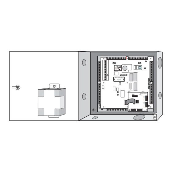
3–1 Section 3: Hardware Specifications Power Requirements: The N-1000-III/IV requires a 16.5 VAC, 50 VA, 60 HZ or 12 VDC linear (2 amp continuous) power supply. Output Power: 12 VDC (10 to 14 volts) 500 mA for readers requiring 12 VDC or motion detector devices (not for use with locking devices). - Page 17 LED D1 DØ +5v GND Shield LED D1 DØ +5v GND Shield Reader 1 Reader 2 Figure 3-1. Enclosure for the N-1000-III/IV . The N-1000 enclosure, shown here with the N-1000-IV panel, has a lock and key, knockouts and a tamper switch. A 12 VDC battery is mounted on the door.
-
Page 18: Section 4: Installation/Panel Layout
INSTALLATION Section 4: Panel Layout The N-1000-III-X has nine screw-down terminal blocks. Each terminal block, in turn, has 12 individual terminal positions, described in the following sections. Figure 4-1 shows the panel with its printed template. The N-1000-IV-X has an additional board in place of TB5 (see Figure 4-2) with four removable wiring terminal blocks for connection to four readers. -
Page 19: 4-1: Four Reader Board (N-1000-Iv Only)
4–2 4–2 4–2 4–2 4–2 N-1000-III/IV N-1000-III/IV N-1000-III/IV N-1000-III/IV N-1000-III/IV Section 4: P Section 4: P Section 4: P Section 4: P Section 4: Panel L anel L anel L anel L anel Layout ayout ayout ayout ayout 4-1: Four Reader Board (N-1000-IV only) The N-1000-IV supports up to four card readers. - Page 20 Shorting these prongs (labeled TEST) will cause the board to generate a simulated card read (with the PIC firmware version ) from each of the four readers. Status LED Northern Computers, Inc. Shield Cable Drain Wire Reader 4 Ground...
Need help?
Do you have a question about the N-1000-III and is the answer not in the manual?
Questions and answers