
Related Manuals for Nortel 700117


Summary of Contents for Nortel 700117
-
Page 1: Hardware Installation Guide
Hardware Installation Guide Alteon Web Switch 10/100/1000 Mbps Web Switches Part Number: 212779, Revision A, December 2001 50 Great Oaks Boulevard San Jose, California 95119 408-360-5500 Main 408-360-5501 Fax www.nortelnetworks.com... - Page 2 Nortel Networks, Inc. assumes no responsibility or liability arising from the use of products described herein, except as expressly agreed to in writing by Nortel Networks, Inc. The use and purchase of this product does not convey a license under any patent rights, trademark rights, or any other intellectual property rights of Nortel Networks, Inc.
- Page 3 Alteon Web Switch Hardware Installation Guide Japanese VCCI Class A Statement: CE Notice: The CE mark on this equipment indicates that this equipment meets or exceeds the following EMC technical standards: EN50024, EN55022, EN50204, EN61000-3-2, EN61000-3-3, EN61000-4-2, EN61000-4-3, EN61000-4-4, and EN61000-4-5, EN61000-4-6, EN61000-4-11. The equipment also meets or exceeds the following safety technical standards: IEC60950 (CB certified with all member deviations), EN60950, and EN60825-1.
- Page 4 Alteon Web Switch Hardware Installation Guide Nordic Lithium Battery Cautions (Norge) ADVARSEL—Litiumbatteri - Eksplosjonsfare. Ved utskifting benyttes kun batteri som anbefalt av apparatfabrikanten. Brukt batteri returneres apparatleverandøren. (Sverige) VARNING—Explosionsfara vid felaktigt batteribyte. Använd samma batterityp eller en ekvivalent typ som rekommenderas av apparattillverkaren. Kassera använt batteri enligt fabrikantens instruktion.
-
Page 5: Table Of Contents
Contents Preface 7 Who Should Use This Book 7 How This Book Is Organized 7 Contacting Us 8 Warranty 8 Chapter 1: The Alteon Web Switch 9 Physical Description 10 Front Panels 10 Alteon 180 Series Web Switches 10 Alteon AD series Web Switches 11 Ports 12 Rear Panel 14 AC Power 14... - Page 6 Alteon Web Switch Hardware Installation Guide Chapter 3: Using the Console Port 23 Connecting a Serial Cable 23 Establishing a Console Connection 25 Upgrading Software 26 Software Already Installed 26 TFTP Download Through CLI 26 Serial Upgrade 26 Troubleshooting 27 Link LED Does Not Light 27 Symptom 27 Cause 27...
-
Page 7: Preface
Preface This manual describes the features and installation process of AD3, AD4, and the Alteon 180 series of Gigabit Ethernet switch hardware. For full documentation on configuring and using the Web switch’s many software features (such as Server Load Balancing and Application Redirection), see the Web OS switch software manuals. -
Page 8: Contacting Us
Outside North America, call 987-288-3700. Warranty Nortel Networks provides a limited warranty on all its switches for a period of one year from the date of shipment. Free technical support and free replacement of hardware is provided for the first 90 days after shipment. Nortel Networks provides a limited warranty on all its switch software for a period of 90 days from date of shipment. -
Page 9: Chapter 1: The Alteon Web Switch
HAPTER The Alteon Web Switch An Alteon Web switch attaches to the network backbone and interconnects servers using 10 Mbps, 100 Mbps, and 1,000 Mbps Ethernet connections. This flexibility off loads server-to- server traffic from the backbone, frees backbone bandwidth, and accelerates client-server performance. -
Page 10: Physical Description
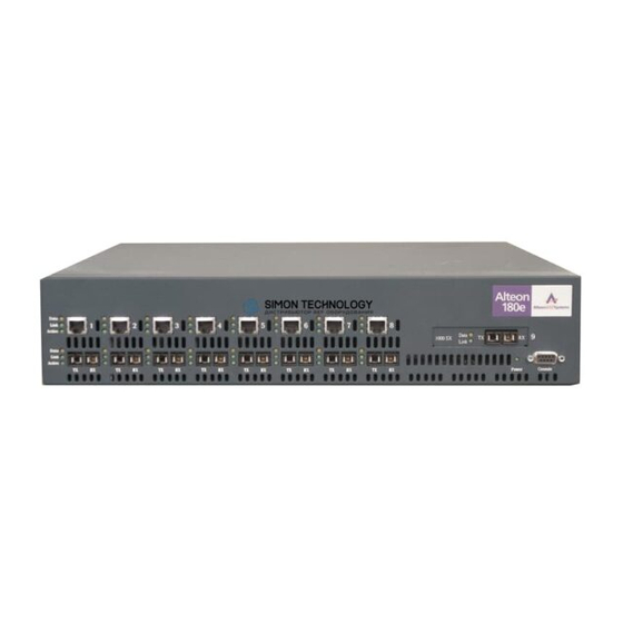
Alteon Web Switch Hardware Installation Guide Physical Description The following sections describe the Alteon Web switch hardware. Front Panels Alteon 180 Series Web Switches Figure 1 Figure 2 illustrate the Alteon 180 series switches. Figure 3 Figure 4 illustrate the Alteon AD3 and Alteon AD4 Web switches. The switch ports are described in “Ports”... -
Page 11: Alteon Ad Series Web Switches
Alteon Web Switch Hardware Installation Guide Alteon AD series Web Switches ACEdirector Data Link Data Status Link Power Console Figure 3 Alteon AD3 Front Panel Figure 4 Alteon AD4 Front Panel Chapter 1: The Alteon Web Switch 212779-A, December 2001... -
Page 12: Ports
Alteon 184 Alteon AD3 Alteon AD4 Model Number 700107 700116 700106 700117 Port Count 10/100Base-T Fast Ethernet Ports 1000Base-SX Gigabit Ethernet Ports The front panel of the Alteon Web switch has the following features: Port 1 through Port 8: RJ-45 network ports –... - Page 13 Alteon Web Switch Hardware Installation Guide The table below describes the lights and conditions represented by the state of the LEDs. Table 3 Front Panel Port LEDs State Description Data Blinking Data detected on the port. No data detected on the port. Link Good link.
-
Page 14: Rear Panel
Alteon Web Switch Hardware Installation Guide Rear Panel AC Power USE ONLY WITH 250V FUSE 250V Figure 5 Alteon Web Switch Rear Panel—AC Powered Models The rear panel of the AC-powered Alteon series Web switches has the following components: A power switch A fuse housing An AC power connector Air vents and exhaust fans... -
Page 15: Chapter 2: Installing The Switch Hardware
HAPTER Installing the Switch Hardware This chapter describes how to install the Alteon Web switch in a rack or on a table. Included Items Your Web switch is shipped with the following items: Two mounting brackets (for rack mounting) Six Phillips screws for installing the mounting brackets Four rubber feet (for tabletop placement of the switch) AC power cord (only for AC-powered models) A console cable... - Page 16 Alteon Web Switch Hardware Installation Guide Powering on the switch. – The DC powered switch requires insulated copper conductor wire of #12 to #22 AWG. The required wire size is related to the length of the wire. For information, refer to the standard NEC 1999.
-
Page 17: Installing The Switch
Alteon Web Switch Hardware Installation Guide Installing the Switch Always observe the precautions outlined in the manuals for this and all other equipment you are installing. Determine whether the unit will be mounted into an equipment rack, or placed free-standing on a shelf or tabletop. -
Page 18: Table-Mounting The Web Switch
Alteon Web Switch Hardware Installation Guide Then, install the switch as shown in the figure below using the appropriate screws for your rack-mount system (four 10-32, 12-24, M5X.8-6H, or M6X1-6H type screws). Figure 8 Rack-Mounted Alteon Web Switch Table-Mounting the Web Switch Attach the four rubber feet to the bottom of the switch. -
Page 19: Connecting Power
Alteon Web Switch Hardware Installation Guide Connecting Power The following instructions are for AC powered and DC powered Alteon switches. AC Power Connect the power cord to the Web switch. Verify that the power switch is in the off position. Plug the switch cord into a properly fused AC outlet. -
Page 20: Connecting Cables To Network Ports
Alteon Web Switch Hardware Installation Guide Connect the other end of each DC power lead to the appropriate wire terminal of your DC power source. Connect the DC “+” (common) switch terminal to the source DC “+” common power terminal. Connect the DC “–”... -
Page 21: Gigabit Ethernet Via The Fiber Optic Sc Connector
Alteon Web Switch Hardware Installation Guide Gigabit Ethernet via the Fiber Optic SC Connector The figure below illustrates an SC-type connector used for Gigabit Ethernet fiber optic connec- tions on the Alteon Web switches: Figure 9 Fiber Optic Connector for Alteon Web Switches The following table lists the cable characteristics for connecting to 1000Base-SX ports. -
Page 22: Automatic Selection Of Redundant Connections
Alteon Web Switch Hardware Installation Guide Automatic Selection of Redundant Connections – This feature is supported only on the Alteon 180 Series Web switches. The Alteon 180 series’ unique dual-media configuration supports automatic bring-up and fail- over between the 10/100 Mbps and 1000 Mbps port-pairs. Order of precedence follows these rules: If both the 10/100 Mbps and 1000 Mbps ports are inactive: If the user activates the Gigabit Ethernet port first (by plugging a live cable into the... -
Page 23: Chapter 3: Using The Console Port
HAPTER Using the Console Port Alteon Web switches have a console port for configuring the switch. This chapter explains how to connect a terminal to the console port. For instructions on using the console to view and configure switch settings, see the Web OS switch software manuals. - Page 24 Alteon Web Switch Hardware Installation Guide Console Cable The console port accepts a straight-through serial cable with a male DB9 connector. Table 6 Pinouts for DB9 Serial Connector DB9 Serial Connector Description Ground Not used The following figures show the pin assignments for the console to use to configure serial cables to terminal connectors with 9-pin or 25-pin connectors.
-
Page 25: Establishing A Console Connection
Alteon Web Switch Hardware Installation Guide Switch Console Port PC Serial Port 25-pin Connector 9-pin Connector Ground * Only the pins for RxD, TxD, and Ground are required. Figure 12 9-pin to 25-pin Connector Pin Assignments – Console cables are not intended for permanent installation and should be disconnected from the console port after configuring the switch. -
Page 26: Upgrading Software
Alteon Web Switch Hardware Installation Guide Upgrading Software Software Already Installed The Alteon Web switch is provided with the software installed and configured with the factory default settings. For more information, refer to the Web OS software manuals. TFTP Download Through CLI Following are outlines of TFTP downloading Web OS software. -
Page 27: Troubleshooting
Alteon Web Switch Hardware Installation Guide Troubleshooting This section contains information about possible problems that may occur or error messages that might display if the switch is not properly installed or configured. Link LED Does Not Light Symptom The green Link LED does not light. When you check the Link state using the console terminal (see the Web OS switch software manuals), the status is reported as down. -
Page 28: Switch Will Not Boot
Alteon Web Switch Hardware Installation Guide Units in a closed or multi-unit rack assembly may have an operating ambient temperature higher than the ambient temperature of the room. The ambient temperature of an operating switch must not exceed 40 C. If the operating ambient temperature cannot be lowered before this maximum is reached, turn off the switch and let it cool. -
Page 29: Appendix A: Specifications
PPENDIX Specifications Supported Standards Spanning Tree Protocol (IEEE 802.1d) Logical Link Control (IEEE 802.2) 10Base-T/100Base-TX (IEEE 802.3, 802.3u) 1000Base-SX (IEEE 802.3z) Flow Control (IEEE 802.3x) Link Negotiation (IEEE 802.3z) Frame Tagging (IEEE 802.1Q) on all ports when VLANs are enabled SNMP support: RFC 1213 MIB-II, RFC 1493 Bridge MIB, RFC 1398 Ethernet-like MIB, RFC 1757 RMON1 (groups 1-4), and RFC 1573 Interface Extensions MIB compliant. -
Page 30: Physical Characteristics
Alteon Web Switch Hardware Installation Guide Physical Characteristics Characteristic Measurement Width 43.18 cm (17.00 inches) (Standard 19" EIA rack mountable) Height 8.81 cm (3.47 inches) Depth 45.72 cm (18.00 inches) Weight 8 kg (18 lb.) Power Requirements AC Power Specification Measurement Auto-ranging power supply 100-240VAC @ 50-60 Hz, 3A... -
Page 31: Environmental Specifications
Alteon Web Switch Hardware Installation Guide Environmental Specifications Condition Operating Specification Storage Specification Temperature 0° to 40° C (+32° to +104° F) –40° to +85° C (–40° to +185° F) Relative humidity 5 to 85% non-condensing 5 to 95% non-condensing (40°... - Page 32 Alteon Web Switch Hardware Installation Guide Appendix A: Specifications 212779A, December 2001...
Need help?
Do you have a question about the 700117 and is the answer not in the manual?
Questions and answers