Table of Contents
Advertisement
Quick Links
Advertisement
Table of Contents

Subscribe to Our Youtube Channel
Related Manuals for Supero Supero X7DBi+


Summary of Contents for Supero Supero X7DBi+
- Page 1 UPER X7DBi+ USER’S MANUAL Revision 1.1...
- Page 2 Clara County in the State of California, USA. The State of California, County of Santa Clara shall be the exclusive venue for the resolution of any such disputes. Supermicro's total liability for all claims will not exceed the price paid for the hardware product.
-
Page 3: Manual Organization
OAT). The X7DBi+ offers a superb solution for intense computing and complex I/O performance, especially ideal for high-end server platforms. Please refer to our web site (http://www.supermicro.com/products/motherboard/) for updates on supported processors. This product is intended to be professionally installed. -
Page 4: Table Of Contents
Manual Organization ....................iii Conventions Used in the Manual .................. iii Chapter 1: Introduction Overview ......................1-1 Checklist ....................1-1 Contacting Supermicro ................1-2 X7DBi+ Image ................1-3 X7DBi+ Layout ................1-4 Quick Reference ..................1-5 Motherboard Features ................1-6 Intel Blackford Chipset: System Block Diagram ........ - Page 5 Table of Contents Power Button ..................2-13 2-5 Connecting Cables ..................2-14 ATX Power Connector ................2-14 Processor Power Connector ..............2-14 Universal Serial Bus ................2-15 Chassis Intrusion ..................2-15 Fan Headers ..................2-16 Keylock ..................... 2-16 ATX PS/2 Keyboard and Mouse Ports ............. 2-17 Serial Ports .....................
- Page 6 X7DBi+ User's Manual Chapter 3: Troubleshooting Troubleshooting Procedures ................3-1 Before Power On ..................3-1 No Power ....................3-1 No Video ....................3-1 Losing the System’s Setup Confi guration ..........3-1 Memory Errors ................... 3-2 Technical Support Procedures ................ 3-2 Frequently Asked Questions ................
-
Page 7: Chapter 1: Introduction
Checklist Congratulations on purchasing your computer motherboard from an acknowledged leader in the industry. Supermicro boards are designed with the utmost attention to detail to provide you with the highest standards in quality and performance. Check that the following items have all been included with your motherboard. If anything listed here is damaged or missing, contact your retailer. -
Page 8: Contacting Supermicro
Super Micro Computer, Inc. 980 Rock Ave. San Jose, CA 95131 U.S.A. Tel: +1 (408) 503-8000 Fax: +1 (408) 503-8008 Email: marketing@supermicro.com (General Information) support@supermicro.com (Technical Support) Web Site: www.supermicro.com Europe Address: Super Micro Computer B.V. Het Sterrenbeeld 28, 5215 ML... -
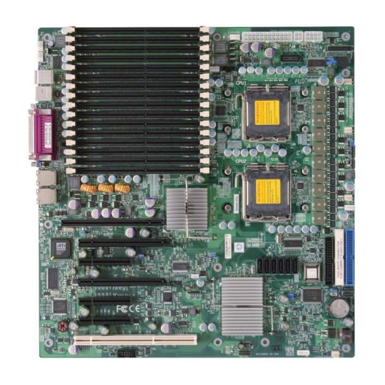
Page 9: X7Dbi+ Image
Chapter 1: Introduction X7DBi+ Image Note: The drawings and pictures shown in this manual were based on the latest PCB Revision available at the time of publishing of the manual. The motherboard you’ve received may or may not look exactly the same as the graphics shown in the manual. -
Page 10: X7Dbi+ Layout
X7DBi+ User's Manual X7DBi+ Motherboard Layout (not drawn to scale) DIMM 4D (Bank4) 8-Pin PWR CPU FAN1 24-Pin ATX PWR DIMM 4C (Bank4) FAN7 FP CTRL 4-Pin PWR DIMM 4B (Bank4) J9B2 Buzzer DIMM 4A (Bank4) J9B1 PSF SMBus PS DIMM 3D (Bank3) KB/Mouse FAN1... -
Page 11: Quick Reference
IDE1 Hard Drive (JIDE1)/Compact Flash Card (JIDE2) KB/Mouse (JKM1) PS2 Keyboard/Mouse Keylock (JK1) Keylock Header SIMLP (Slot 7) SIMLP (Supermicro Intelligent Management) Add-On Card Slot Connector OH LED (JOH1) Overheat LED Parallel Port (J21) Parallel (Printer) Port PWR LED/Speaker (JD1) PWR LED(pins1-3)/SpeakerHeader (pins 4-7) PWR LED (LE1) PWR LED Indicator (Note6 on Pg.1-4) -
Page 12: Motherboard Features
• Three PCI-Express x4 slots (x8 physical, x4 signal) (Slot 2, Slot 3, and Slot 5) • Two PCI-Express x8 slots (x16 physical, x8 signal) (Slot 4 and Slot 6) • One 64-bit PCI-X 133 MHz slot (Slot 1) • One SIMLP (Supermicro Intelligent Management) add-on card slot (Slot 7) BIOS • 8 Mb Phoenix ®... - Page 13 Chapter 1: Introduction ACPI Features • Slow blinking LED for suspend state indicator • Main switch override mechanism • ACPI Power Management • Keyboard Wakeup from Soft-off Onboard I/O • Six SATA2 ports (supporting RAID0, RAID1, RAID10, RAID5*) (*For the Windows Operating System only.) •...
- Page 14 X7DBi+ User's Manual PROCESSOR#2 PROCESSOR#1 ISL6307 ISL6307 1067/1333 1067/1333 MT/S MT/S FBD CHNL0 PCI-E X8 PORT 5000P #4,5 FBD CHNL1 FBD CHNL2 PCI-E X8 PORT #6,7 FBD CHNL3 PORT PORT #2,3 PCIE X8 PCIE X4 ATA 100 PORT PORT IDE CONN PCI-E X4 PORT EXP.
-
Page 15: Chipset Overview
Chapter 1: Introduction Chipset Overview Built upon the functionality and the capability of the 5000P chipset, the X7DBi+ motherboard provides the performance and feature set required for dual processor- based servers with confi guration options optimized for communications, presenta- tion, storage, computation or database applications. The 5000P chipset supports a single or dual Intel 64-bit Quad core/dual core processor(s) with front side bus speeds of up to 1.333 GHz. -
Page 16: Special Features
X7DBi+ User's Manual Special Features Recovery from AC Power Loss The feature allows the user to set the power state after a power outage. You can select Power-Off for the system power to remain off after a power loss. Select Power-On for the system power to be turned on after a power loss. -
Page 17: Acpi Features
Chapter 1: Introduction notify the user of certain system events. For example, you can also confi gure Supero Doctor to provide you with warnings when the system temperature, CPU temperatures, voltages and fan speeds go beyond a pre-defi ned range. ACPI Features ACPI stands for Advanced Confi... -
Page 18: Power Supply
X7DBi+ User's Manual (WOL) to connect to the 3-pin header on a Network Interface Card (NIC) that has WOL capability. In addition, an onboard LAN controller can also support WOL without any connection to the WOL header. The 3-pin WOL header is to be used with a LAN add-on card only. - Page 19 Chapter 1: Introduction The Super I/O provides functions that comply with ACPI (Advanced Confi guration and Power Interface), which includes support of legacy and ACPI power manage- ment through an SMI or SCI function pin. It also features auto power management to reduce power consumption.
- Page 20 X7DBi+ User's Manual Notes 1-14...
-
Page 21: Chapter 2: Installation
Chapter 2: Installation Chapter 2 Installation Static-Sensitive Devices Electrostatic Discharge (ESD) can damage electronic com ponents. To prevent dam- age to your system board, it is important to handle it very carefully. The following measures are generally suffi cient to protect your equipment from ESD. Precautions •... -
Page 22: Processor And Heatsink Installation
X7DBi+ User's Manual Processor and Heatsink Installation When handling the processor package, avoid placing direct pressure on the label area of the fan. Notes: 1. Always connect the power cord last and always remove it before adding, removing or changing any hardware components. Make sure that you install the processor into the CPU socket before you install the CPU heatsink. - Page 23 Chapter 2: Installation North Center Edge 3. Use your thumb and your index fi nger to hold the CPU at the North Center Edge and the South Center Edge of the CPU. 4. Align CPU Pin1 (the CPU corner marked with a triangle) against the socket corner that is marked with a South Center Edge triangle cutout.
-
Page 24: Installation Of The Heatsink
X7DBi+ User's Manual Installation of the Heatsink CEK Heatsink Installation CEK Passive Heatsink 1. Do not apply any thermal grease to the heatsink or the CPU die because the re- quired amount has already been applied. 2. Place the heatsink on top of the CPU so that the four mounting holes are aligned with those on the retention mechanism. -
Page 25: Mounting The Motherboard In The Chassis
Chapter 2: Installation 1. Unscrew and remove the heatsink screws from the motherboard in the sequence as show in the picture on the right. 2. Hold the heatsink as shown in the picture on the right and gently wriggle the heatsink to loosen it from the CPU. -
Page 26: Installing Dimms
X7DBi+ User's Manual Installing DIMMs Note: Check the Supermicro web site for recommended memory modules. CAUTION Exercise extreme care when installing or removing DIMM modules to prevent any possible damage. Also note that the memory is interleaved to improve performance. -
Page 27: Installing And Removing Dimms
Chapter 2: Installation Note 2: Due to memory allocation to system devices, memory remaining available for operational use will be reduced when 4 GB of RAM is used. The reduction in memory availability is disproportional. (See the Memory Availability Table below.) Possible System Memory Allocation &... -
Page 28: Back Panel Connectors/Io Ports
X7DBi+ User's Manual Control Panel Connectors/IO Ports The I/O ports are color coded in conformance with the PC 99 specifi cation. See the fi gure below for the colors and locations of the various I/O ports. A. Back Panel Connectors/IO Ports Figure 2-3. -
Page 29: Front Control Panel
These connectors are designed specifi cally for use with Supermicro server chassis. See the fi gure below for the descriptions of the various control panel buttons and LED indicators. Refer to the following section for descriptions and pin defi... -
Page 30: Front Control Panel Pin Defi Nitions
X7DBi+ User's Manual C. Front Control Panel Pin Defi nitions NMI Button NMI Button Pin Defi nitions (JF1) The non-maskable interrupt button Pin# Defi nition header is located on pins 19 and 20 Control of JF1. Refer to the table on the right Ground for pin defi... -
Page 31: Hdd Led
Chapter 2: Installation HDD LED HDD LED Pin Defi nitions (JF1) The HDD LED connection is located Pin# Defi nition on pins 13 and 14 of JF1. Attach a hard drive LED cable here to display HD Active disk activity (for any hard drives on the system, including Serial ATA and IDE). -
Page 32: Overheat/Fan Fail Led
X7DBi+ User's Manual Overheat/Fan Fail LED (OH) OH/Fan Fail LED Pin Defi nitions (JF1) Connect an LED to the OH/Fan Fail Pin# Defi nition connection on pins 7 and 8 of JF1 to provide advanced warnings of chassis Ground overheating or fan failure. Refer to the OH/Fan Fail Indicator table on the right for pin defi... -
Page 33: Reset Button
Chapter 2: Installation Reset Button The Reset Button connection is located Reset Button on pins 3 and 4 of JF1. Attach it to the Pin Defi nitions (JF1) hardware reset switch on the computer Pin# Defi nition case. Refer to the table on the right for Reset pin defi... -
Page 34: Connecting Cables
X7DBi+ User's Manual Connecting Cables ATX Power 20-pin Connector Pin Defi nitions Pin# Defi nition Pin # Defi nition ATX Power Connector +3.3V +3.3V There are a 24-pin main power sup- -12V +3.3V ply connector(JPW1) and an 8-pin CPU PWR connector (JPW3) on the PS_ON motherboard. -
Page 35: Universal Serial Bus
Chapter 2: Installation Universal Serial Bus (USB) Back Panel USB (USB0/1) There are fi ve USB 2.0 (Universal Se- Pin# Defi nitions rial Bus) ports/headers on the moth- erboard. Two of them are Back Panel USB ports (USB#0/1:JUSB1), and the other three are Front Panel Acces- Ground sible USB headers (USB#2/3:JUSB2,... -
Page 36: Fan Headers
X7DBi+ User's Manual Fan Headers Fan Header Pin Defi nitions (Fan1-8) The X7DBi+ has six chassis/system fan Pin# Defi nition headers (Fan1 to Fan6) and two CPU Fans Ground (Fans 7/8). (Note: Fans 5/6/7/8 are 4-pin fans. +12V However, Pins 1-3 of these fan headers are Tachometer backward compatible with the traditional 3-pin PWR Modulation... -
Page 37: Serial Ports
Chapter 2: Installation ATX PS/2 Keyboard and PS/2 Keyboard and PS/2 Mouse Ports Mouse Port Pin Defi nitions The ATX PS/2 keyboard and the PS/2 Pin# Defi nition mouse are located at JKM1. The Data mouse port is above the keyboard port. -
Page 38: Wake-On-Ring
X7DBi+ User's Manual Wake-On-Ring Wake-On-Ring Pin Defi nitions (WOR) The Wake-On-Ring header is des- Pin# Defi nition ignated JWOR1. This feature allows Ground your computer to "wake up" when re- Wake-up ceiving an incoming call to the modem when the system is in suspend mode. See the table on the right for pin defi... -
Page 39: Glan (Ethernet Ports)
Chapter 2: Installation GLAN 1/2 (Giga-bit Ethernet Ports) Two G-bit Ethernet ports are desig- nated JLAN1 and JLAN2 on the IO backplane. These ports accept RJ45 GLAN1 GLAN2 type cables. Power LED/Speaker Speaker Connector On the JD1 header, pins 1-3 are for Pin Setting Defi... -
Page 40: Power Fault
See the table on the right Note: This feature is only available when using for pin defi nitions. Supermicro redundant power supplies. Alarm Reset If three power supplies are installed Alarm Reset... - Page 41 Chapter 2: Installation SMB Header Pin Defi nitions A System Management Bus header is Pin# Defi nition located at J18. Connect the appropri- Data ate cable here to utilize SMB on your Ground system. Clock No Connection SMBus PS (I C) Connector PWR SMB Pin Defi...
-
Page 42: T-Sgpio Headers
X7DBi+ User's Manual T-SGPIO Headers SGPIO Pin Defi nitions There are two T-SGPIO (Serial General Purpose Input/Output) headers located Pin# Defi nition Defi nition at (J29, J30) on the motherboard. These headers support serial link interfaces Ground Data for the onboard SATA connectors. See Load Ground the table on the right for pin defi... -
Page 43: Compact Flash Card Pwr Connector
Chapter 2: Installation Compact Flash Card PWR Compact Flash Card PWR Connector Connector Jumper Defi nition A Compact Flash Card Power Connector Compact Flash is located at JWF1. For the Compact Power On Flash Card or the Compact Flash Compact Flash Power Off Jumper (JCF1) to work properly, please connect the Compact Flash Card power... -
Page 44: Jumper Settings
X7DBi+ User's Manual Jumper Settings Explanation of Jumpers Connector Pins To modify the operation of the motherboard, jumpers can be used to choose between optional settings. Jumper Jumpers create shorts between two pins to change the function of the connector. Pin 1 is identifi ed with a Setting square solder pad on the printed circuit Pin 1-2 short... -
Page 45: Clear Cmos
Chapter 2: Installation CMOS Clear JBT1 is used to clear CMOS. Instead of pins, this "jumper" consists of contact pads to prevent the accidental clearing of CMOS. To clear CMOS, use a metal object such as a small screwdriver to touch both pads at the same time to short the connection. -
Page 46: 3Rd Pwr Supply Pwr Fault
X7DBi+ User's Manual 3rd PWR Supply PWR Fault Detect (J3P) 3rd PWR Supply PWR Fault The system can notify you in the event Jumper Settings of a power supply failure. This feature is Jumper Setting Defi nition available when three power supply units Closed Enabled are installed in the chassis with one act-... - Page 47 Chapter 2: Installation Compact Flash Master/Slave Select A Compact Flash Master (Primary)/Slave Compact Flash Card Master/ Slave Select (Secondary) Select Jumper is located Jumper Defi nition at JCF1. Close this jumper to enable Open Slave (Secondary) Compact Flash Card. For the Compact Closed Master (Primary) Flash Card or the Compact Flash Jumper...
-
Page 48: Onboard Indicators
X7DBi+ User's Manual Onboard Indicators L i n k Activity GLAN LEDs Rear View There are two GLAN ports on the moth- GLAN Activity Indicator erboard. Each Gigabit Ethernet LAN port has two LEDs. The yellow LED indicates Color Status Defi... - Page 49 Chapter 2: Installation Overheat LED/Fan Fail Overheat LED (JOH1) Pin Defi nitions Pin# Defi nition The JOH1 header is used to connect 5vDC an LED to provide warnings of chassis OH Active overheating. This LED will blink to in- dicate a fan failure. Refer to the table OH/Fan Fail LED on right for pin defi...
- Page 50 X7DBi+ User's Manual Parallel Port, Floppy Drive, Hard Disk Drive and SIMLP Connections Note the following when connecting the fl oppy and hard disk drive cables: • The fl oppy disk drive cable has seven twisted wires. • A red mark on a wire typically designates the location of pin 1. •...
-
Page 51: Floppy Connector
Read Data Ground Side 1 Select Ground Diskette SIMLP Slot There is a SIMLP (Supermicro Intel- ligent Management) add-on card slot (Slot 7) on the motherboard. Refer to the layout below for the IPMI Slot location. A. Floppy DIMM 4D (Bank4) -
Page 52: Ide Connectors
X7DBi+ User's Manual IDE Connectors IDE Drive Connectors Pin Defi nitions There are two IDE Connectors (JIDE1: Pin# Defi nition Pin # Defi nition Blue, JIDE2: White) on the mother- Reset IDE Ground board. The blue IDE connector (JIDE1) Host Data 7 Host Data 8 is designated the Primary IDE Drive. -
Page 53: Chapter 3: Troubleshooting
Chapter 3: Troubleshooting Chapter 3 Troubleshooting Troubleshooting Procedures Use the following procedures to troubleshoot your system. If you have followed all of the procedures below and still need assistance, refer to the ‘Technical Support Procedures’ and/or ‘Returning Merchandise for Service’ section(s) in this chapter. Note: Always disconnect the power cord before adding, changing or installing any hardware components. -
Page 54: Memory Errors
Technical Support Procedures Before contacting Technical Support, please take the following steps. Also, note that as a motherboard manufacturer, Supermicro does not sell directly to end-users, so it is best to fi rst check with your distributor or reseller for troubleshooting services. -
Page 55: Frequently Asked Questions
4. Distributors: For immediate assistance, please have your account number ready when placing a call to our technical support department. We can be reached by e-mail at support@supermicro.com or by fax at: (408) 503-8000, option Frequently Asked Questions Question: What are the various types of memory that my motherboard can... -
Page 56: Returning Merchandise For Service
You can obtain service by calling your vendor for a Returned Merchandise Authorization (RMA) number. For faster service, You can also request a RMA authorization online (http://www.supermicro. com/support/rma/). When returning to the manufacturer, the RMA number should be prominently displayed on the outside of the shipping carton, and mailed prepaid or hand-carried. -
Page 57: Chapter 4: Bios
Note: Due to periodic changes to the BIOS, some settings may have been added or deleted and might not yet be recorded in this manual. Please refer to the Manual Download area of the Supermicro web site <http://www.supermicro.com> for any changes to the BIOS that may not be refl ected in this manual. -
Page 58: Running Setup
X7DBi+ User's Manual Running Setup *Default settings are in bold text unless otherwise noted. The BIOS setup options described in this section are selected by choosing the ap- propriate text from the main BIOS Setup screen. All displayed text is described in this section, although the screen display is often all you need to understand how to set the options (see the next page). -
Page 59: Main Bios Setup Menu
Chapter 4: BIOS Main BIOS Setup Menu Main Setup Features System Time To set the system date and time, key in the correct information in the appropriate fi elds. Then press the <Enter> key to save the data. System Date Using the arrow keys, highlight the month, day and year fi... - Page 60 X7DBi+ User's Manual IDE Channel 0 Master/Slave and IDE Secondary Master/Slave These settings allow the user to set the parameters of the slots specifi ed. Press <Enter> to activate the following submenu items for detailed options. Set the correct confi gurations accordingly. Type This item allows you to select the type of IDE hard drive.
- Page 61 Chapter 4: BIOS Native Mode Operation (Available when SATA Controller Mode below is set to Compatible) Select the native mode for ATA. The options are: Serial ATA, and Auto. SATA Controller Mode Select Compatible to allow the SATA and PATA drives to be automatically-detected and be placed in the Legacy Mode by the BIOS.
-
Page 62: Advanced Setup
X7DBi+ User's Manual Advanced Setup Choose Advanced from the Phoenix BIOS Setup Utility main menu with the arrow keys. You should see the following display. The items with a triangle beside them have sub menus that can be accessed by highlighting the item and pressing <Enter>. Boot Features Access the submenu to make changes to the following settings. -
Page 63: Power Loss Control
Chapter 4: BIOS hits the power button. If set to 4-sec., the system will power off when the user presses the power button for 4 seconds or longer. The options are Instant-off and 4-sec override. Resume On Modem Ring Select On to “wake your system up” when an incoming call is received by your modem. - Page 64 X7DBi+ User's Manual memory area of Block 0-512K. Select Write Back to allow the CPU to write data back directly from the buffer without writing data to the System Memory for fast CPU data processing and operation. The options are Uncached, Write Through, Write Protect, and Write Back.
- Page 65 Chapter 4: BIOS Default Primary Video Adapter This feature allows the user to specify which video adapter to be used as the default primary video adapter--the onboard video adapter or others. The options are Other and Onboard Video. Emulated IRQ Solutions When Enabled, the Emulated IRQ Scheme will allow PCI devices to run on legacy operating systems that use the MSI mechanism to generate INTX compatible interrupts.
- Page 66 X7DBi+ User's Manual Enable Master This setting allows you to enable the selected device as the PCI bus master. The options are Enabled and Disabled. Latency Timer This setting allows you to set the clock rate for Bus Master. A high-priority, high- throughout device may benefi...
-
Page 67: Advanced Chipset Control
Chapter 4: BIOS Advanced Chipset Control Access the submenu to make changes to the following settings. Warning : Take Caution when changing the Advanced settings. Incorrect values entered may cause the system to malfunction. Also, a very high DRAM frequency or incorrect DRAM timing may cause system instability. When this occurs, revert the setting to the default setting. - Page 68 X7DBi+ User's Manual High Temperature DRAM Operation When set to Enabled, the BIOS will refer to the SPD table to set the maximum DRAM temperature. If disabled, the BIOS will set the maximum DRAM temperature based on a predefi ned value. The options are Enabled and Disabled. AMB Thermal Sensor Select Enabled to enable the thermal sensor embedded in the Advanced Memory Buffer on a fully buffered memory module for thermal monitoring.
-
Page 69: Usb Function
Chapter 4: BIOS RDTSC Instruction embedded in a CPU. The High Precision Event Timer is used to replace the 8254 Programmable Interval Timer. The default setting is No. USB Function Select Enabled to enable the function of USB devices specifi ed. The settings are Enabled and Disabled. -
Page 70: Advanced Processor Options
X7DBi+ User's Manual Advanced Processor Options Access the submenu to make changes to the following settings. CPU Speed This is a display that indicates the speed of the installed processor. Frequency Ratio (Available when supported by the CPU.) The feature allows the user to set the internal frequency multiplier for the CPU. The options are: Default, x6, and x7. - Page 71 Chapter 4: BIOS Adjacent Cache Line Prefetch (Available when supported by the CPU.) The CPU fetches the cache line for 64 bytes if this option is set to Disabled. The CPU fetches both cache lines for 128 bytes as comprised if Enabled. The options are Disabled and Enabled.
- Page 72 X7DBi+ User's Manual I/O Device Confi guration Access the submenu to make changes to the following settings. KBC Clock Input This setting allows you to select clock frequency for the keyboard controller. The options are 6MHz, 8MHz, 12MHz, and 16MHz. Serial Port A This setting allows you to determine how Serial Port A is managed by the system.
-
Page 73: Floppy Disk Controller
Chapter 4: BIOS Interrupt This setting allows you to select the IRQ (interrupt request) for the parallel port. The options are IRQ5 and IRQ7. Mode This feature allows you to specify the parallel port mode. The options are Output only, Bi-Directional, EPP and ECP. DMA Channel This item allows you to specify the DMA channel for the parallel port. -
Page 74: Console Redirection
X7DBi+ User's Manual Console Redirection Access the submenu to make changes to the following settings. COM Port Address This item allows you to specify which COM port to direct the remote console to: Onboard COM A or Onboard COM B. This setting can also be Disabled. BAUD Rate This item allows you to set the BAUD rate for Console Redirection.The options are 300, 1200, 2400, 9600, 19.2K, 38.4K, 57.6K, and 115.2K. -
Page 75: Hardware Monitoring
Chapter 4: BIOS Hardware Monitoring This feature allows the user to monitor system health and review the status of each item as displayed. CPU Overheat Alarm This option allows the user to select the CPU Overheat Alarm setting which de- termines when the CPU OH alarm will be activated to provide warning of possible CPU overheat. - Page 76 X7DBi+ User's Manual User intervention: No action is required. However, consider checking the cooling fans and the chassis ventilation for blockage. High – The PECI Agent is running hot. This is a ‘caution’ level since the PECI Agent ’s ‘Temperature Tolerance’ has been reached (or has been exceeded) and may activate an overheat alarm.
- Page 77 Chapter 4: BIOS IPMI (The option is available only when an IPMI card is installed in the system.) IPMI Specifi cation Version: This item displays the current IPMI Version. Firmware Version: This item displays the current Firmware Version. System Event Logging Select Enabled to enable IPMI Event Logging.
- Page 78 X7DBi+ User's Manual OS Boot Watch Dog Set to Enabled to enable OS Boot Watch Dog. The options are Enabled and Disabled. Timer for Loading OS (Minutes) This feature allows the user to set the time value (in minutes) for the previous item: OS Boot Watch Dog by keying-in a desired number in the blank.
- Page 79 Chapter 4: BIOS Realtime Sensor Data This feature display information from motherboard sensors, such as temperatures, fan speeds and voltages of various components. IPMI LAN Confi guration The following features allow the user to confi gure and monitor IPMI LAN settings. 4-23...
-
Page 80: Mac Address
X7DBi+ User's Manual VLAN Tagging Select Enabled to enable Virtual LAN(s) for IPMI connections and allow the user to confi gure VLAN settings. The options are Enabled and Disabled. VLAN ID If VLAN Tagging above is set to Enabled, this item allows the user to change the VLAN ID. -
Page 81: Security Settings
Chapter 4: BIOS Security Settings Choose Security from the Phoenix BIOS Setup Utility main menu with the arrow keys. You should see the following display. Security setting options are displayed by highlighting the setting using the arrow keys and pressing <Enter>. All Security BIOS settings are described in this section. -
Page 82: Boot Settings
X7DBi+ User's Manual Boot Settings Choose Boot from the Phoenix BIOS Setup Utility main menu with the arrow keys. You should see the following display. See details on how to change the order and specs of boot devices in the Item Specifi c Help window. All Boot BIOS settings are described in this section. -
Page 83: Exit
Chapter 4: BIOS Exit Choose Exit from the Phoenix BIOS Setup Utility main menu with the arrow keys. You should see the following display. All Exit BIOS settings are described in this section. Exit Saving Changes Highlight this item and hit <Enter> to save any changes you have made and to exit the BIOS Setup utility. - Page 84 X7DBi+ User's Manual Notes 4-28...
-
Page 85: Appendix A: Bios Beep Codes
Appendix A: BIOS Error Beep Codes Appendix A BIOS Error Beep Codes During the POST (Power-On Self-Test) routines, which are performed each time the system is powered on, errors may occur. Non-fatal errors are those which, in most cases, allow the system to continue the boot-up process. - Page 86 X7SBi+ User’s Manual Notes...
-
Page 87: Appendix B: Installing The Windows Os
South Bridge RAID Settings before you install the Windows OS and other software drivers. To confi gure RAID settings, please refer to RAID Confi guration User Guides posted on our website at www.supermicro.com/support/manuals. B-1 Installing the Windows XP/2000/2003 OS for... - Page 88 Windows XP/2000/2003 installation. After the Windows XP/2000/2003 OS Installation is completed, the system will automatically reboot. Insert the Supermicro Setup CD that came with your motherboard into the CD Drive during system boot, and the main screen will display.
-
Page 89: Appendix C: Installing Other Software Programs
Appendix C: Installing Other Software Programs and Drivers Appendix C Installing Other Software Programs and Drivers Installing Other Drivers After you've installed the Windows Operating System, a screen as shown below will appear. You are ready to install software programs and drivers that have not yet been installed. - Page 90 X7DBi+ User's Manual Confi guring Supero Doctor III The Supero Doctor III program is a Web-base management tool that supports remote management capability. It includes Remote and Local Management tools. The local management is called the SD III Client. The Supero Doctor III program included on the CDROM that came with your motherboard allows you to monitor the environment and operations of your system.
- Page 91 Supero Doctor III Interface Display Screen-II (Remote Control) Note: SD III Software Revision 1.0 can be downloaded from our Web site at: ftp:// ftp.supermicro.com/utility/Supero_Doctor_III/. You can also download SDIII User's Guide at: http://www.supermicro.com/PRODUCT/Manuals/SDIII/UserGuide.pdf. For Linux, we will still recommend that you use Supero Doctor II.
- Page 92 X7DBi+ User's Manual Notes...
- Page 93 (Disclaimer continued) The products sold by Supermicro are not intended for and will not be used in life support systems, medical equipment, nuclear facilities or systems, aircraft, aircraft devices, aircraft/emergency communication devices or other critical systems whose failure to perform be reasonably expected to result in signifi cant injury or loss of life or catastrophic property damage.
Need help?
Do you have a question about the Supero X7DBi+ and is the answer not in the manual?
Questions and answers