Table of Contents
Advertisement
Quick Links
Advertisement
Table of Contents

Related Manuals for Fostex AR501


Summary of Contents for Fostex AR501
- Page 1 AR501 MIC PREAMPLIFIER Owner's Manual...
-
Page 2: Table Of Contents
Table of contents Names and functions ....Input and Output ..... . Switches and LED's inside Battery Cover . -
Page 3: Names And Functions
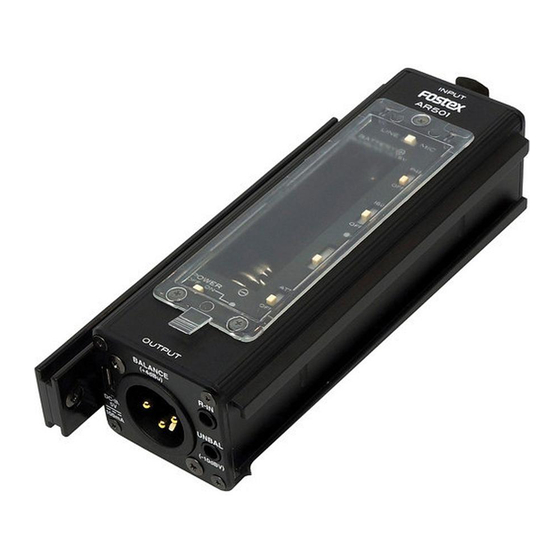
1. Names and functions < Input Panel > INPUT Balanced input XLR-3P (Female) < Output Panel > R-IN Audio signal input for Right Stereo mini jack UNBAL OUT Unbalanced output Stereo mini jack BALANCED OUT DC-IN Balanced output DC power inlet XLR-3P (Male) micro USB... -
Page 6: Input And Output
2. Input and Output < Input > INPUT Connector Connect here the output from microphone or line level equipment. Use INPUT SEL switch according to the type of device connected. (Refer to 3. Switches and LED’ s inside Battery Cover.) [Connector]: XLR (Female) / Pin: 3 pins (Pin No.2 as HOT) [Input impedance] LINE: 10kΩ or higher MIC: 2kΩ or higher [Input level] INPUT SEL Nominal -60/-45/-30/-20 dBu -40/-25/-10/0 dBu LINE +4dBu +24dBu... - Page 7 < Output > BALANCED OUT Connector Output the line level audio signal in balanced configuration. [Connector]: XLR (Male) / Pins: 3 pins / No.2 as HOT [Nominal output level]: +4dBu [Max. output level]: +24dBu [Applicable load impedance]: 10kΩ or more UNBALANCED OUT Connector Output the audio signal in unbalanced configuration. (The same signal will appear on both L and R channels.) You can reduce the output level by using ATT switch. ((Refer to 3. Switches and LED’ s inside Battery Cover)). [Connector]: Stereo mini jack / ø3.5 mm [Nominal output level]: -10dBV [Max. output level]: +10dBV Nominal -10dBV +10dBV -50dBV -30dBV...
- Page 8 < Misc. > R-IN connector Connecting a line level audio signal here will result an output via UNBALANCED OUT connector Right channel. It is useful when connecting another AR501 to perform in stereo. [Connector]: Stereo mini jack / ø3.5mm DC-IN connector Use to connect an external power source. Recommended DC voltage is 5V. An ordinary mobile battery pack can be used. [Connector]: micro USB [Input voltage]: 5V±3% [Current consumption]: 100mA peak. Note: When icoming voltage goes below the above spec. or if it cuts out, AR501 will automatically switch the power source to internal battery.
-
Page 9: Switches And Led's Inside Battery Cover
3. Switches and LED's inside Battery Cover INPUT SEL Switch INPUT SEL Switch Use INPUT SEL switch according to the type of equipment Use INPUT SEL switch according to the type of equipment connected. connected. For dynamic or condenser type microphone LINE For line level equipment such as an audio mixer. * When choosing LINE, no signal becomes available on BALANCED OUT connector. PHANTOM POWER Switch Power supply for condenser microphone No voltage supplied. 48V voltage is supplied to INPUT connector. 24V will be supplied at power saving mode. - Page 10 HPF (High Pass Filter) Switch Used to reduce low frequency noise such as wind blow on the microphone or hum noise generated by AC power facility. Reducing the frequency range of 80Hz and below. Reducing the frequency range of 160Hz and below. * Attenuation: -6dB/oct. GAIN Switch and PEAK Indicator Used to adjust the microphone amp gain according to the microphone sensitivity. Set the GAIN switch appropriately referring to the PK (PEAK indicator) LED and the input level of equipment connected to OUTPUT. MIC Sensitivity (dBu) GAIN (dB) LINE * When the GAIN is adjusted properly acccording to the chart above, the nominal level will appear via OUTPUT connector.
- Page 11 Battery Compartment POWER Switch Insert a piece of AA battery. Main power switch Type of battery: Ni-MH (Nickel of AR501 Metal Hydride), Alkaline POWER INDICATOR Power indicator LED. (For detail, refer to next page.) OUTPUT ATT Switch Used to attenuate the signal level at UNBALANCED OUT. Set to ON when connecting to low input equipment such as mic in of DSLR camera. No attenuation (nominal output level: -10dBV) Attenation applied (nominal output level: -50dBV)
- Page 12 Flashing red 3 times rapidly If you operate the PHANTOM POWER switch from OFF to ON to OFF during the setting up period, AR501 will enter Power saving mode. It will reduce the internal circuitry working voltage and cut down the power consumption by approx. 40%. (The supply voltage at P48 is going to be 24V during the power saving mode.)
- Page 13 [Internal battery]: During normal mode operation BATT. Lighting pattern amount Flashing: ••• High G Green 2 times Flashing: ••• High Y Yellow 2 times Flashing: ••• G Green 2 times Red 1 time Flashing: ••• Y Yellow 2 times R Red 1 time Lit solid Forced to ••• Run out R Red * Replace the battery when Red LED becomes flashing. * Replace the battery immediately when Red LED is lit solid as the power is forced to OFF on both internal circuitry as well as P48.
- Page 14 [Internal battery]: During power saving mode operation BATT. Lighting pattern amount Flashing: ••• High G Green Flashing: ••• High Y Yellow Flashing: G Green 1 time ••• Red 1 time Flashing: ••• Y Yellow 1 time R Red 1 time Lit solid Forced to ••• Run out R Red * The supply voltage at P48 is 24V during the power saving mode. * Replace the battery when Red LED becomes flashing.
-
Page 15: Power Supply
4. Power < Internal Battery > AR501 uses a piece of AA battery. The sutied type of battery is N-MH rechargeable battery or Alkaline battery. * AR501 does not have battery charging function. Operating time reference value. Normal Mode Power saving mode Battery Type P48 (Power to mic) - Page 16 DC-IN Connector AR501 can be powered by connecting an external power source to DC-IN such as mobile battery pack. Memo * When powered by an external power source, AR501 does not con- sume the power from internal battery. * The power indicator becomes lit (use of internal battery makes the indicator flashing.). * If the external power cuts out with some reason, it will automatically switch the power source to the internal battery.
-
Page 17: Chassis
5. Chassis < Screw hole for tripod > AR501 provides 1/4” thread on the bottom chassis so that you can attach it to a standard tripod and camera gear. < Shoe rail > By inserting the joint plate comes in the package here, multiple number of AR501 can be jointed. P l e a s e r e f e r t o < J o i n t > o n t h e s e c t i o n 6 . ... - Page 18 < Attaching user label > AR501 has a pit on the bottom chassis to stick a user label for the users’ convenience. Use it for attaching a label in the way you like such as company ID and administrative control number plate. Since the pit is retracted, it avoids the label getting damaged when attaching a tripod. Recommended label dimensions: 41 x 13 mm, Corner R 2.5 mm...
-
Page 19: Accessories
Other purpose of joint is; fixing the joint to somewhere like a wall us- ing 3 mm in diameter screw holes, then attach the AR501 to the joint. Recommended screw: 3 mm in diameter, more than 10 mm in length, counter-sunk type screw (other type cannot be used). - Page 20 < Reference dimensions > < Cable > Used to connect AR501 unbalanced output to other equipment such as a DSLR camera and audio recorder and also to connect 2 x AR501's in cascade. For the convenience of handling, a curl cord is used.
-
Page 21: Typical Connections
Microphone OUTPUT (UNBAL) * If the audio input level of DSLR is fixed to MIC level, set the AR501 ATT switch to ATT position. Refer to the DSLR owner's manual for the details. * When using a line level source such as an audio mixer and wishing to convert the output from BALANCED to UNBALANCED by AR501, set the INPUT SEL switch to LINE. -
Page 22: Input And Output Specifications
8. Input and Output Specifications < Analog Input > • Balanced XLR-3-31 type (Electrically balanced) 1: GND, 2: HOT, 3: COLD LINE Input impedance: 10 kΩ or more Nominal input level: +4 dBu Max. input level: +24 dBu Input impedance: 2 kΩ or more Nominal input level: -60 ~ -20 dBu Max. - Page 23 • Unbalanced ø3.5 mm stereo mini jack Applicable load impedance: 10 kΩ or more Nominal output level: -10 dBV (-50 dBV at ATT ON) Max. output level: +10 dBV (-30 dBV at ATT ON) < Power supply for microphone > 48 ±...
-
Page 24: Performances
9. Performance < Frequency Response > • LINE IN - OUPUT (Unbalanced) 20 ~ 20,000 Hz ± 1 dB (reference level) • MIC IN - OUTPUT (Balanced) GAIN: Low (-20 dB) 20 ~ 20,000 Hz ± 1 dB (reference level) GAIN: Hi (-60 dB) 20 ~ 20,000 Hz ±... -
Page 25: Dimensions And Weight
10. Dimensions and Weight < Dimensions > W 42.8 mm x H 31.6 mm x D 116 mm < Weight > Approx. 110 g (without battery) Approx. 150 g (with eneloop AA battery x 1) - Page 26 < External View > 42.8 mm...
-
Page 27: Block Diagram
11. Block Diagram... - Page 28 FOSTEX COMPANY 1-1-109, Tsutsujigaoka, Akishima City, Tokyo, 196-8550, Japan PRINTED IN JAPAN AUGUST 2013 578831 (8588125000)
Need help?
Do you have a question about the AR501 and is the answer not in the manual?
Questions and answers