DURKOPP ADLER 867 Operating Manual
Hide thumbs
Also See for 867:
- Durkopp adler (192 pages) ,
- Service instructions manual (164 pages) ,
- Parts list (153 pages)
Table of Contents
Advertisement
Quick Links
Advertisement
Table of Contents

Related Manuals for DURKOPP ADLER 867


Summary of Contents for DURKOPP ADLER 867
- Page 1 Operating Manual...
- Page 2 All rights reserved. Property of Dürkopp Adler AG and protected by copyright. Any reuse of these contents, including extracts, is prohibited without the written approval in advance of Dürkopp Adler AG. Copyright © Dürkopp Adler AG - 2012...
-
Page 3: Table Of Contents
Venting the sewing foot .................44 5.8.1 Mechanical lifting with the knee lever ............44 5.8.2 Electro-pneumatic lifting with a foot pedal ..........44 Locking the sewing feet in the upper position........45 5.10 Setting the sewing foot pressure ............46 Operating manual 867 Version 01.0 - 12/2012... - Page 4 Fitting the oil extraction line..............86 7.10 Fitting the knee lever ................87 7.10.1 Fitting the mechanical knee lever............87 7.10.2 Fitting the electric knee lever..............88 7.11 Fitting the control panel ................. 89 Operating manual 867 Version 01.0 - 12/2012...
- Page 5 Pneumatic connection .................103 7.13.1 Fitting the maintenance unit..............103 7.13.2 Setting the operating pressure.............104 7.13.3 Pneumatic foot lifting ................104 7.14 Lubrication ...................105 7.15 Sewing text ..................107 Disposal....................109 Appendix ....................111 Table plate drawings................111 Table of maximum speeds..............114 Operating manual 867 Version 01.0 - 12/2012...
- Page 6 Contents Operating manual 867 Version 01.0 - 12/2012...
-
Page 7: About This Manual
Failure to observe the instructions in the manual • Improper use • Unauthorized modifications to the machine • The deployment of untrained personnel • Damage during transport • Using spare parts not approved Operating manual 867 Version 01.0 - 12/2012... -
Page 8: Symbols Used
Length of the machine arms, number of adjusting wheels, position of the stitch adjustment lever, presence of the keypad, etc. When this makes no difference to the handling steps, the figures show only one machine version as an example. Operating manual 867 Version 01.0 - 12/2012... -
Page 9: Safety Instructions
• Threading • Replacing the needle or other sewing tools • Leaving the workplace • Performing maintenance work and repairs Operating manual 867 Version 01.0 - 12/2012... - Page 10 Work on live components and equipment is prohibited. Exceptions are defined in DIN VDE 0105. Missing or faulty spare parts could impair safety and damage the machine. Therefore only use original spare parts from the manu- facturer. Operating manual 867 Version 01.0 - 12/2012...
-
Page 11: Signal Words And Symbols Used In Safety Instructions
Attention:Material damage is possible. In the case of dangers to personnel, the following symbols indicate the type of hazard: General danger Danger due to electric shock Danger due to sharp objects Danger due to crushing Operating manual 867 Version 01.0 - 12/2012... - Page 12 Type and source of the danger Consequences in the event of noncompliance Measures for avoiding the danger This is what a hazard note looks like for a hazard that could result in material damage if not complied with. Operating manual 867 Version 01.0 - 12/2012...
-
Page 13: Performance Description
Performance description 3 Performance description 3.1 Features The Dürkopp Adler 867 is a flatbed sewing machine for double lockstitches. General technical characteristics • Large or extra-large vertical hook • Transport: Lower transport, needle transport and alternating foot-upper transport • DC drive for all submodels •... -
Page 14: Declaration Of Conformity
The machine complies with the European regulations specified in the declaration of conformity or in the installation declaration. 3.3 Intended use The Dürkopp Adler 867 is intended for sewing moderately heavy to heavy material. Depending on the submodel the following needle sizes are to be used: •... -
Page 15: Data Overview By Submodel
Maximum sewing foot stroke Positive operating pressure [bar] Air consumption [NL] Length/width/height [mm] 690/220/460 Weight/with direct drive [kg] 55/59 Rated voltage [V/Hz] Depends on the drive package Rated power [kVA] Depends on the drive package Operating manual 867 Version 01.0 - 12/2012... - Page 16 Maximum sewing foot stroke Positive operating pressure [bar] Air consumption [NL] Length/width/height [mm] 690/320/ 690/220/460 Weight/with direct drive [kg] 55/59 Rated voltage [V/Hz] Depends on the drive package Rated power [kVA] Depends on the drive package Operating manual 867 Version 01.0 - 12/2012...
- Page 17 Maximum sewing foot stroke Positive operating pressure [bar] Air consumption [NL] Length/width/height [mm] 690/220/460 Weight/with direct drive [kg] 55/59 Rated voltage [V/Hz] Depends on the drive package Rated power [kVA] Depends on the drive package Operating manual 867 Version 01.0 - 12/2012...
- Page 18 (*only with reversing mechanism) Maximum sewing foot stroke Positive operating pressure [bar] Air consumption [NL] Length/width/height [mm] 740/220/460 Weight/with direct drive [kg] Rated voltage [V/Hz] 230 V - 50/60 Hz Rated power [kVA] 375 W Operating manual 867 Version 01.0 - 12/2012...
- Page 19 Maximum sewing foot stroke Positive operating pressure [bar] Air consumption [NL] Length/width/height [mm] 1090/220/460 Weight/with direct drive [kg] 85/89 Rated voltage [V/Hz] Depending on the drive package Rated power [kVA] Depending on the drive package Operating manual 867 Version 01.0 - 12/2012...
- Page 20 Positive operating pressure [bar] Air consumption [NL] Length/width/height [mm] 1390/ 1090/220/460 220/460 Weight/with direct drive [kg] 85/89 95/99 Rated voltage [V/Hz] Depending on the drive package Rated power [kVA] Depending on the drive package Operating manual 867 Version 01.0 - 12/2012...
-
Page 21: Additional Equipment And Manuals
Additional equipment and manuals can be requested from the Dürkopp Adler Applications Center (APC). E-mail: marketing@duerkopp-adler.com Additional manuals and further Documentation are available in the download area of the Dürkopp Adler Internet site: http://www.duerkopp-adler.com/de/main/Support/downloads. Operating manual 867 Version 01.0 - 12/2012... - Page 22 Performance description Operating manual 867 Version 01.0 - 12/2012...
-
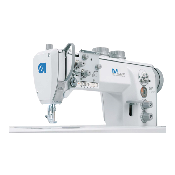
Page 23: Device Description
(7) - Bobbin winder for the hook thread (8) - Adjusting wheels for the stitch length (9) - Oil level indicator (10) - Handwheel (11) - Stitch adjustment lever (12) - Unwinding bracket with thread reel holder Operating manual 867 Version 01.0 - 12/2012... - Page 24 Device description Operating manual 867 Version 01.0 - 12/2012...
-
Page 25: Operating Instructions
1. Press the main switch (3) down to position I. The indicator lamps (1) and (2) light up. To switch off the power: 1. Press the main switch (3) up to position 0. The indicator lamps (1) and (2) go out. Operating manual 867 Version 01.0 - 12/2012... -
Page 26: Inserting And Replacing The Needle
Faults caused by an incorrect hook clearance After inserting a thinner needle: • Missing stitches • Thread damage After inserting a thinner needle: • Damage to the hook tip • Damage to the needle Operating manual 867 Version 01.0 - 12/2012... -
Page 27: Needle Change On 1-Needle Machines
3. Pull the needle out towards the bottom. 4. Insert the new needle. 5. Important: Align the needle so that the groove (3) faces the hook (4). 6. Tighten the fastening screw (2). Operating manual 867 Version 01.0 - 12/2012... -
Page 28: Needle Change On 2-Needle Machines
5. Important: Align the needles so that the grooves (3) face away from each other. Each groove then faces the hook that belongs to this needle. 6. Tighten the fastening screws (2) on both sides. Operating manual 867 Version 01.0 - 12/2012... -
Page 29: Changing Needles On Switchable Needle Bars
5. Important: Align the needles so that the grooves (3) face away from each other. Each groove then faces the hook that belongs to this needle. 6. Tighten the fastening screws (2) on both sides. Operating manual 867 Version 01.0 - 12/2012... -
Page 30: Threading In The Needle Thread
(2) - Thread reel holder 1. Fit the thread reel on the thread reel holder (2). 2. Insert the thread from the rear to the front through a hole in the guide on the unwinding bracket (1). Operating manual 867 Version 01.0 - 12/2012... -
Page 31: Needle Thread Threading On 1-Needle Machines
8. Guide the thread under the diverter pin (4) to the thread ten- sioning spring. 9. Lift the tightening lever (1) with the thread. 10. Pull the thread under the spring tip (2). Operating manual 867 Version 01.0 - 12/2012... - Page 32 4 cm with the thread catcher (16) in the highest position. Important:Check the thread length. The short thread cutter does not function correctly when the loose thread end is too long. Operating manual 867 Version 01.0 - 12/2012...
-
Page 33: Needle Thread Threading On 2-Needle Machines
2. First guide the left-hand needle thread through the left-hand guide holes and around the left-hand tensioning screw triangle (1). 3. First guide the left-hand needle thread through the right-hand guide holes and around the right-hand tensioning screw triangle (2). Operating manual 867 Version 01.0 - 12/2012... -
Page 34: Needle Thread Threading On Machines With A Clean Seam Start
6. Guide the thread clockwise around the main tensioner (4). 7. Guide the thread around the diverter pin (3) from above. 8. Proceed with step 9 ( Section 5.3.1 Needle thread threading on 1-needle machines, Page 29) in a normal threading scheme. Operating manual 867 Version 01.0 - 12/2012... -
Page 35: Inserting And Winding On The Hook Thread
(2) - Thread reel holder 1. Fit the thread reel on the thread reel holder (2). 2. Insert the thread from the rear to the front through a hole in the guide on the unwinding bracket (1). Operating manual 867 Version 01.0 - 12/2012... - Page 36 7. Clamp the thread behind the cutter (3) and tear off the loose end behind it. 8. Fit the bobbin on the bobbin shaft (2). 9. Turn the bobbin clockwise until it clicks. 10. Pull the bobbin lever (1) up. Operating manual 867 Version 01.0 - 12/2012...
- Page 37 4. Tear off the thread behind the cutter. 5. Insert the full bobbin in the hook ( Section 5.5 Replacing the hook thread bobbin, Page 36). 6. Repeat the winding-on procedure with an empty bobbin, as described above. Operating manual 867 Version 01.0 - 12/2012...
-
Page 38: Replacing The Hook Thread Bobbin
5. Pull the hook thread under the tensioning spring (3). 6. Feed the hook thread through the slot (1) and pull it approx. 3 cm further. 7. Close up the bobbin housing flap (6). Operating manual 867 Version 01.0 - 12/2012... -
Page 39: Thread Tension
Figure 16: Thread interlacing (1) - Identical needle thread and hook thread tension (2) - Hook thread tension higher than needle thread tension (3) - Needle thread tension higher than hook thread tension Operating manual 867 Version 01.0 - 12/2012... -
Page 40: Adjusting The Needle Thread Tension
The main tension should be set as low as possible. The thread interlacing should be exactly in the middle of the material being sewn. Faults due to excessively high tension • Crimping • Thread breakage Operating manual 867 Version 01.0 - 12/2012... - Page 41 Short initial thread: 1. Turn the adjusting screw of the pre-tensioner (1) clockwise. Long initial thread: 1. Turn the adjusting screw of the pre-tensioner (1) counterclock- wise. Operating manual 867 Version 01.0 - 12/2012...
- Page 42 Switching additional tension on: 1. Slide handle (2) of the lever (1) all the way to the left. Switching additional tension off: 1. Slide handle (2) of the lever (1) all the way to the right. Operating manual 867 Version 01.0 - 12/2012...
-
Page 43: Removing Blocking Of The Needle Thread Tension
ECO machines: The needle thread tensioner is automatically opened when the sewing foot is lifted via the knee lever. • CLASSIC machines: The needle thread tensioner is automatically opened when the thread is cut. Operating manual 867 Version 01.0 - 12/2012... -
Page 44: Adjusting The Hook Thread Tension
The hook thread tension is adjusted using the adjusting screw (1). To increase the tension: 1. Turn the adjusting screw (1) clockwise. To reduce the tension: 1. Turn the adjusting screw (1) counterclockwise. Operating manual 867 Version 01.0 - 12/2012... -
Page 45: Setting The Thread Regulator
1. Loosen the regulator screw (1). • To increase the tension: Slide the thread regulator (2) to the right • To reduce the tension: Slide the thread regulator (2) to the left 2. Tighten the regulator screw (1). Operating manual 867 Version 01.0 - 12/2012... -
Page 46: Venting The Sewing Foot
The sewing feet remain up as long as the foot pedal is pressed halfway back. 1. Press the foot pedal (1) fully back. The thread cutter is activated and the sewing feet are raised. Operating manual 867 Version 01.0 - 12/2012... -
Page 47: Locking The Sewing Feet In The Upper Position
The lever swivels back up and the lock is removed. CAUTION Risk of crushing when lowering the sewing foot. Do not hold your hands under the sewing foot when the upper position is released via the pedal or lever. Operating manual 867 Version 01.0 - 12/2012... -
Page 48: Setting The Sewing Foot Pressure
(1) - Adjusting wheel for the sewing foot To increase the sewing foot pressure: 1. Turn the adjusting wheel (1) clockwise. To reduce the sewing foot pressure: 1. Turn the adjusting wheel (1) counterclockwise. Operating manual 867 Version 01.0 - 12/2012... -
Page 49: Removing Blocking Of The Adjusting Wheel
3. Turn the adjusting wheel for the sewing foot pressure (3) ( Section 5.10 Setting the sewing foot pressure, Page 46). 4. Fit the retaining plate (2). 5. Tighten the fastening screw (1). Operating manual 867 Version 01.0 - 12/2012... -
Page 50: Setting The Sewing Foot Stroke
On ECO machines, do not press the pedal too far forwards when sewing with a large sewing foot stroke and large stitch lengths. Do not change the potentiometer setting on CLASSIC machines. Operating manual 867 Version 01.0 - 12/2012... -
Page 51: Setting The Stroke Height
(2) - Adjusting wheel for the elevated sewing foot stroke sewing foot stroke (CLASSIC equipment) To increase the sewing foot stroke: 1. Turn the adjusting wheel clockwise. To reduce the sewing foot stroke: 1. Turn the adjusting wheel counterclockwise. Operating manual 867 Version 01.0 - 12/2012... -
Page 52: Quick Stroke Adjustment Via Knee Switch
1. Set the toggle switch (2) to the lower position. • To switch on the elevated sewing foot stroke: Push the knee lever knee switch (1) to the right and keep it pressed. Operating manual 867 Version 01.0 - 12/2012... -
Page 53: Removing Blocking Of The Sewing Foot Pressure Adjustment Wheel
1. Loosen the fastening screws (2). 2. Turn the adjusting wheel for the sewing foot stroke (1) ( Section 5.11 Setting the sewing foot stroke, Page 48). 3. Tighten the fastening screws (2). Operating manual 867 Version 01.0 - 12/2012... -
Page 54: Stitch Length
(4) - Upper adjusting wheel for the larger stitch length To reduce the stitch length: 1. Turn the adjusting wheel clockwise. To increase the stitch length: 1. Turn the adjusting wheel counterclockwise. Operating manual 867 Version 01.0 - 12/2012... -
Page 55: Sewing With 2 Stitch Lengths
Do not attempt to use brute force to select a smaller stitch length at the upper adjusting wheel. Operating manual 867 Version 01.0 - 12/2012... -
Page 56: Removing Blocking Of The Adjusting Wheel
2. Turn the stitch length adjusting wheels (1) ( Section 5.12 Stitch length, Page 52). 3. Insert a 3 mm hex key through the access holes (2) and tighten the blocking screws for the stitch length adjusting wheels. Operating manual 867 Version 01.0 - 12/2012... -
Page 57: Sewing Backwards
1. Slowly push the stitch adjustment lever (1) down. The stitch length becomes smaller. In the lower end posi- tion, the machine sews backwards with the stitch length selected at the adjusting wheels. Operating manual 867 Version 01.0 - 12/2012... -
Page 58: Quick Functions On The Keypad
1. Press the key. The function is activated. The key lights up. Deactivating a key function 1. Press the key again. The function is deactivated. The key does not light up any more. Operating manual 867 Version 01.0 - 12/2012... - Page 59 Key for the vertical cutter (7): (only for machines with a vertical cutter) Key (7) switches on the vertical cutter. When lifting the sewing foot the cutter is automatically switched off and the key (7) is deactivated. Operating manual 867 Version 01.0 - 12/2012...
-
Page 60: Transferring A Key Function To The Additional Switch
To transfer a key function: 1. Turn all screws to their basic position (2) so that the slots are horizontal. 2. Turn the screw under the desired key 90° so that the slot is vertical (3). Operating manual 867 Version 01.0 - 12/2012... -
Page 61: Switching The Binder
The binder follows the same path as the transporter. You cannot directly switch between plus and minus. Deactivate the respectively illuminated key as described in operating step 2 before switching the other key. Operating manual 867 Version 01.0 - 12/2012... -
Page 62: Switching Switchable Needle Bars
You cannot switch off both needle bars at the same time. When a needle bar is switched off and you press the key for the other needle bar, this switches on the disabled needle bar so that both needle bars are in use. Operating manual 867 Version 01.0 - 12/2012... -
Page 63: Operating The Controller
• DAC ECO and DAC CLASSIC controllers: The operating manual is provided in the accessory pack delivered with the controller. The operating manual is also available in the download area at www.duerkopp-adler.com Operating manual 867 Version 01.0 - 12/2012... -
Page 64: Sewing
2. Push the material to be sewn into the initial position. Sewing: 1. Press the foot pedal forwards to the pedal position +1: The machine sews. The sewing speed increases the further forward the pedal is pressed. Operating manual 867 Version 01.0 - 12/2012... - Page 65 1. Press the foot pedal back completely to the pedal position -2: The machine sews the end strip and the thread cutter cuts the thread. The machine stops, needles and sewing feet are up. 2. Remove the sewn material. Operating manual 867 Version 01.0 - 12/2012...
- Page 66 Operating instructions Operating manual 867 Version 01.0 - 12/2012...
-
Page 67: Maintenance
Take care that no particles fly into the oil pan. ATTENTION Malfunctions possible due to machine contamination. Sewing dust and thread remains can impair the operation of the machine. Clean the machine at regular intervals as described in the manual. Operating manual 867 Version 01.0 - 12/2012... - Page 68 2. Remove any sewing dust and thread remains using a com- pressed-air pistol or a brush. ATTENTION Possible damage to the paintwork from solvent-based cleaners. Solvent-based cleaners damage the paintwork of the machine. Use only solvent-free substances for cleaning the machine. Operating manual 867 Version 01.0 - 12/2012...
-
Page 69: Cleaning The Motor Fan Sieve
(2) - Motor fan sieve Cleaning steps: 1. Switch off the power supply at the main switch. 2. Remove any sewing dust and thread remains using a com- pressed-air pistol or a brush. Operating manual 867 Version 01.0 - 12/2012... -
Page 70: Checking The Oil Level
Too little or too much oil can cause damage to the machine. Check the oil level on a daily basis and top up oil so that the oil level is always between the minimum and maximum mark- ings. Operating manual 867 Version 01.0 - 12/2012... - Page 71 If the oil level falls below the minimum level marking (3), on CLASSIC machines the oil level indicator lights up in red. 1. Switch the sewing machine off and on again after filling with oil. The red light goes out. Operating manual 867 Version 01.0 - 12/2012...
- Page 72 Oil is a pollutant and must not enter the sewage sys- tem or the soil. Carefully collect old oil and dispose of oil and oil- contaminated machine parts in the legally pre- scribed manner. Operating manual 867 Version 01.0 - 12/2012...
-
Page 73: Checking The Pneumatic System
Machine damage possible due to incorrect pressure. An incorrect pressure can cause damage to the machine. Check the pressure on a daily basis. Have the pressure adjusted by qualified specialists if the pres- sure deviates from the reference value. Operating manual 867 Version 01.0 - 12/2012... - Page 74 Machine damage possible if there is too much water. Too much water can cause damage to the machine. Check the water level every day and drain the condensation water if there is too much water in the water separator. Operating manual 867 Version 01.0 - 12/2012...
-
Page 75: Repairs
Contacts for repair in the event of damage to the machine: Dürkopp Adler AG Potsdamer Str. 190 33719 Bielefeld Ph. +49 (0) 180 5 383 756 Fax +49 (0) 521 925 2594 Email: service@duerkopp-adler.com Internet: www.duerkopp-adler.com Operating manual 867 Version 01.0 - 12/2012... - Page 76 Maintenance Operating manual 867 Version 01.0 - 12/2012...
-
Page 77: Set-Up Instructions
(9) - Oil pan (2) - Table plate (6) - Knee lever/switch (10) - Machine upper (3) - Drawer (7) - Maintenance unit section (4) - Frame (8) - Control (11) - Thread reel holder Operating manual 867 Version 01.0 - 12/2012... -
Page 78: Removing The Transport Securing Devices
All transport securing devices must be removed prior to set-up. 1. Remove the lashing straps and wooden blocks from the machine upper section, the table and the frame. 2. Remove the supporting wedges between the machine arm and needle plate. Operating manual 867 Version 01.0 - 12/2012... -
Page 79: Fitting The Frame Components
6. Important: Turn the adjusting screw (7) so that the frame has even contact with the ground. * Frame components for long arm machines have 2 cross bars and the other frame components have 1 cross bar. Operating manual 867 Version 01.0 - 12/2012... -
Page 80: Completing The Table Plate
7. Insert the upper section support (1) in the hole. 8. Fit the lower part of the hinge into the recess (2) and screw tight. 9. Fit the rubber corners in the corner protrusions (6). Operating manual 867 Version 01.0 - 12/2012... -
Page 81: Completing A Long Arm Table Plate
7. Insert the plug (6) in the hole. 8. Fit the lower part of the hinge into the recess (2). 9. Fit the rubber corners in the corner protrusions (5). Operating manual 867 Version 01.0 - 12/2012... -
Page 82: Fastening The Table Plate To The Frame
Figure 51: Fastening the table plate to the frame (1) - Screw holes and screws 1. Place the table plate on the head sections of the inner bars. 2. Screw the table plate firmly in place at the screw holes (1). Operating manual 867 Version 01.0 - 12/2012... -
Page 83: Setting The Working Height
2. Set the table plate to the desired height. Important: Pull out or push in the table plate evenly at both sides to prevent it from jamming. 3. Tighten the screws (1) on the frame bars. Operating manual 867 Version 01.0 - 12/2012... -
Page 84: Controller
394342 190122 190142 160122 260122 190145 190125 190146 190322 Short arm 190342 190445 190425 29020 Efka DC1550/DA321G 29040 290122 290142 290322 290342 490322 290445 190122-70 190322-70 190342-70 Long arm 290122-70 290322-70 290342-70 290342-100 Operating manual 867 Version 01.0 - 12/2012... -
Page 85: Fitting The Control
1. Screw the control (2) onto the 4 screw holders (3) under the table plate. 2. Clamp the power cable of the control (2) into the strain relief mechanism (1). 3. Screw the strain relief (1) under the table plate. Operating manual 867 Version 01.0 - 12/2012... -
Page 86: Fit The Pedal And Setpoint Device
5. Hang the pedal rod (1) with the ball socket on the setpoint device (5) and the pedal (4). 6. Pull the pedal rod (1) to the correct length: Correct setting: 10° inclination with pedal (4) released 7. Tighten the screw (2). Operating manual 867 Version 01.0 - 12/2012... -
Page 87: Inserting The Machine Upper Section
2. Fit the machine upper section from above at an angle of 45°. 3. Insert the upper hinge parts (2) into the rubber inlays (1). 4. Fold the machine upper section down and insert it in the recess. Operating manual 867 Version 01.0 - 12/2012... -
Page 88: Fitting The Oil Extraction Line
1. Fold the machine upper section back. 2. Screw the filter (2) into the oil pan with the plastic adapter to the right. 3. Insert the tube of the oil extraction line (1) into the plastic adapter. Operating manual 867 Version 01.0 - 12/2012... -
Page 89: Fitting The Knee Lever
2. Fit the transmission rod (3) in the oil pan. 3. Screw the knee lever (1) rods together. 4. Guide the rod (1) through the hole in the oil pan (2) and connect it to the transmission rod (3). Operating manual 867 Version 01.0 - 12/2012... -
Page 90: Fitting The Electric Knee Lever
2. Guide the connecting cable (2) to the back between the oil pan and the control. 3. Insert the plug (3) of the connecting cable in the socket of the control. Operating manual 867 Version 01.0 - 12/2012... -
Page 91: Fitting The Control Panel
5. Guide the cable through the hole in the table plate. 6. Insert the plug of the connecting cable in the socket of the control. 7. Screw on the valve cover (2) and upper machine cover (1). Operating manual 867 Version 01.0 - 12/2012... -
Page 92: Electrical Connection
Pull out the power plug before fitting and connect- ing the sewing lamp and sewing lamp transformer Make sure the power plug cannot be unintention- ally reinserted. Operating manual 867 Version 01.0 - 12/2012... - Page 93 5. Lay the connecting cable in the machine arm and feed the cable through the hole in the table plate ( Section 7.11 Fitting the control panel, Page 89). 6. Stick the sticker with safety instructions onto the front of the control. Operating manual 867 Version 01.0 - 12/2012...
- Page 94 3. Loosen the adaptor cover screws (3). 4. Connect the supply line: • For sewing lamps to be additionally fitted to the X3 connection (1) • For integrated LED sewing lamps on the 24V/X5 connection (2) Operating manual 867 Version 01.0 - 12/2012...
- Page 95 Important:Do not press so hard that the board is pressed in. 9. Connect the blue cable to the upper terminal (3) and the brown cable to the lower terminal (4). 10. Fasten the front panel with the 4 screws. Operating manual 867 Version 01.0 - 12/2012...
-
Page 96: Establishing Equipotential Bonding
2. Feed the earthing cable from the connection (1) on the rear side of the controller through the cutout in the table plate and plug it onto the tab connector (2) on the base plate. Operating manual 867 Version 01.0 - 12/2012... -
Page 97: Connecting The Controller
DAC ECO and DAC CLASSIC controllers: The operating manual is provided in the controller accessory pack. The operating manual is also available in the download area at www.duerkopp-adler.com. Figure 66: DAC CLASSIC connection sockets Operating manual 867 Version 01.0 - 12/2012... -
Page 98: Connecting The Sewing Machine Upper Section
1:1. Important: For this reason, when using the Hall sensor it is important to ensure that the maximum speed for the respective submodel is not exceeded. Operating manual 867 Version 01.0 - 12/2012... - Page 99 The operating manual is provided in the controller acces- sory pack. • DAC ECO and DAC CLASSIC controllers: The operating manual is provided in the controller acces- sory pack. The operating manual is also available in the download area at www.duerkopp-adler.com. Operating manual 867 Version 01.0 - 12/2012...
- Page 100 If this is not the case then the handwheel must be readjusted. For more information see Service manual. 10. Fit the handwheel cover and handwheel and screw tight. Operating manual 867 Version 01.0 - 12/2012...
-
Page 101: Connecting The Electrical Knee Switch
2. Insert the plug of the knee switch in the socket of the respective controller: • DAC ECO and DAC CLASSIC controllers: Socket (2) on the rear side of the controller • Efka DC1550/DA321G controller: Socket KN19 (3) on the front side of the controller Operating manual 867 Version 01.0 - 12/2012... -
Page 102: Fitting The M-Control Circuit Board
1. Fitting the circuit board: • Machines with a binder: between the frame (1) and cable duct (2) • Machines with switchable needle bars: At the right next to the setpoint device angle bracket (3) Operating manual 867 Version 01.0 - 12/2012... - Page 103 The position of the switch (1) depends on the submodel: • Machines with a binder: Position 1 • Machines with switchable needle bars: Position 2 • Machines with a clean seam start: Additional manual 0791 867708 Operating manual 867 Version 01.0 - 12/2012...
-
Page 104: Setting Machine-Specific Parameters
The parameter sheet is provided in the controller accessory pack. 1. Set parameter F-290 according to the specifications in Parameter sheet. For submodel 867-290342-100 only: 2. Set parameter F-111 to 2500 min or less. Operating manual 867 Version 01.0 - 12/2012... -
Page 105: Pneumatic Connection
2. Connect the machine tube (4) coming out of the upper section to the maintenance unit (3) at the top right. 3. Connect the system connection tube (2) to the pneumatic sys- tem. Operating manual 867 Version 01.0 - 12/2012... -
Page 106: Setting The Operating Pressure
• To reduce the pressure: Turn the rotary handle (1) coun- terclockwise. 3. Push the turning handle (1) down. 7.13.3 Pneumatic foot lifting Installation information is provided in Additional manual 0791 867704. Operating manual 867 Version 01.0 - 12/2012... -
Page 107: Lubrication
Machine damage possible due to incorrect oil level. Too little or too much oil can cause damage to the machine. On the first filling, only add oil up a level 2 mm below the maximum level mark. Operating manual 867 Version 01.0 - 12/2012... - Page 108 Oil is a pollutant and must not enter the sewage sys- tem or the soil. Carefully collect old oil and dispose of oil and oil- contaminated machine parts in the legally pre- scribed manner. Operating manual 867 Version 01.0 - 12/2012...
-
Page 109: Sewing Text
11. Transfer the desired quick function from the keypad to the addi- tional switch. 12. Start the sewing test at low speed. 13. Increase the sewing speed continuously until the working speed is reached. Operating manual 867 Version 01.0 - 12/2012... - Page 110 Set-up instructions Operating manual 867 Version 01.0 - 12/2012...
-
Page 111: Disposal
Disposal 8 Disposal The customer is responsible for disposal of the machine and packaging materials. The respectively applicable legal regulations must be observed for disposal. Operating manual 867 Version 01.0 - 12/2012... - Page 112 Disposal Operating manual 867 Version 01.0 - 12/2012...
-
Page 113: Appendix
Appendix 9 Appendix 9.1 Table plate drawings Dimensions for manufacturing a tabletop, part 1 Operating manual 867 Version 01.0 - 12/2012... - Page 114 Appendix Dimensions for manufacturing a tabletop, part 2 Operating manual 867 Version 01.0 - 12/2012...
- Page 115 Appendix Dimensions for manufacturing a tabletop, part 2 Operating manual 867 Version 01.0 - 12/2012...
-
Page 116: Table Of Maximum Speeds
Appendix 9.2 Table of maximum speeds Maximum speeds, part 1 Operating manual 867 Version 01.0 - 12/2012... - Page 117 Appendix Maximum speeds, part 2 Operating manual 867 Version 01.0 - 12/2012...
- Page 118 Appendix Operating manual 867 Version 01.0 - 12/2012...
- Page 120 DÜRKOPP ADLER AG Potsdamer Straße 190 33719 Bielefeld GERMANY Phone +49 (0) 521 / 925-00 E-mail marketing@duerkopp-adler.com www.duerkopp-adler.com...