Table of Contents
Advertisement
Advertisement
Table of Contents

Related Manuals for EAW JFL213


Summary of Contents for EAW JFL213
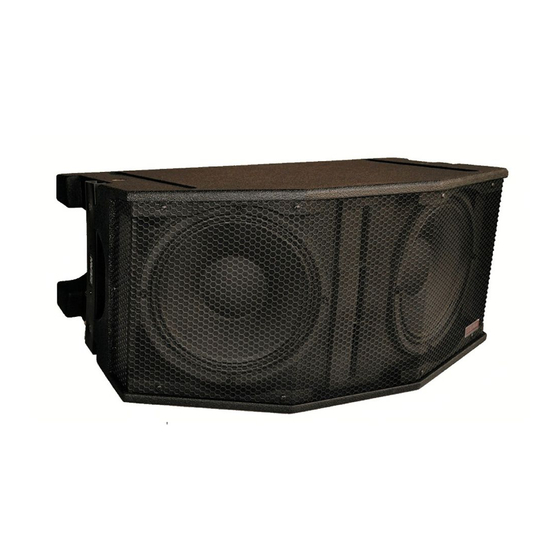
- Page 1 OWNER’S MANUAL JFL213 JFL118 OUDSPEAKERS...
- Page 2 JFL213 and JFL118 Loudspeakers...
-
Page 3: Table Of Contents
OVERVIEW..........................7 ENGINEERING DESIGN ....................... 7 SYSTEM BLOCK DIAGRAM ....................7 USER ADJUSTMENTS......................8 5.4.1 JFL213 HF Shading – Single-Amp Mode ................8 5.4.2 JFL213 HF Shading – Bi-Amp Mode .................. 8 AMPLIFIER POWER REQUIREMENTS................8 5.5.1 Power Ratings ........................9 INPUT CONNECTIONS...................... -
Page 4: Read This First
EAW transactions are made with the assumption that the purchaser is a qualified individual or will have only qualified individuals perform work with the equipment. EAW will not be liable for any damages arising from the use of equipment sold to purchaser. -
Page 5: Introduction
18 inch subwoofer. This manual provides information about the design, configuration, and operation of JFL213 and JFL118 Line Array. It is intended to be used in conjunction with the Windows®-based EAW Resolution software. Please thoroughly familiarize yourself with this manual. -
Page 6: Eaw Resolution Results
JFL118 subwoofers are designed to complement the JFL213 & JFL210 loudspeakers to both extend the low frequency response and provide more output for the upper low frequencies. JFL118 subwoofers may either be ground stacked, flown as part of a JFL213 & JFL210 array, or flown separately alongside a JFL213 & JFL210 array. -
Page 7: Suspending Jfl118 Subwoofers
4.3.3 Suspending JFL118 Subwoofers The JFL118 enclosure rigging is designed to directly couple to an FB221 Fly Bar and JFL213 or JFL210 enclosures. As such, the JFL118 can be rigged seamlessly with JFL213 or JFL210s. See the FB221 Rigging & Ground Stack Instructions for more detailed information on rigging a JFL118. -
Page 8: User Adjustments
The block diagrams above show the possible signal flows for a single JFL213 with JFL118. Use the same processor outputs for additional JFL213s and JFL118s on the same mix bus, i.e. “Left”, “Right”, or “Fill”. USER ADJUSTMENTS 5.4.1 JFL213 HF Shading – Single-Amp Mode The JFL213 has a switchable HF character while in single-amp mode, controlled by the three position toggle labeled “HF Shading.”... -
Page 9: Power Ratings
Use as the input to the JFL213. NL4 #2: Use the second connector to loop the full range signal to the next JFL213. Note that an additional signal can be carried on pins 2 +/- without affecting the JFL213’s operation. Owner’s Manual... -
Page 10: Bi-Amp Mode
Two are used for sub and high-passed signal input, while the third is used as an output to loop the high-passed signal to JFL213, JFL210 or other loudspeakers. These connectors mate with Neutrik NLT4FX, NL4FC, and all other NL4-compatible in-line cable connectors. -
Page 11: Rigging Overview
CAUTION: A JFL213 weighs approximately 28 kg / 62 lb. This, along with the physical size, means that one person may be able to lift and carry it. However, always use proper lifting tech- niques to avoid injury. -
Page 12: A Note On Eyebolts
Anchor Shackles. Minimum allowable Shackle size is 0.75 T, 9 mm / 0.31 in. h. Choose a target array tilt angle as guided by EAW Resolution. Hoist the array to its desired trim height using the front point. Once trim is achieved, use the rear point to set the array tilt angle. -
Page 13: Jfl118 Arrays
Anchor Shackle. Minimum allowable Shackle size is 0.75 T, 9 mm / 0.31 in. h. Choose a target array tilt angle as guided by EAW Resolution. Hoist the array to its desired trim height using the front point. Once trim is achieved, use the rear point to set the array tilt angle. -
Page 14: Tripod And Pole Mounting
TRIPOD AND POLE MOUNTING 6.4.1 Tripod Mounting The JFL213 may be mounted on a tripod loudspeaker stand with a 35 mm / 1.38 in diameter pole. The tripod loudspeaker stand must be rated to support minimum 60 kg / 132 lb. The JFL213’s integral pole-mount holes allow 0°... -
Page 15: Service And Maintenance
EAW Loudspeaker Owner’s Manual for general Service, Maintenance, and Troubleshooting instructions. PARTS REPLACEMENT KITS In the event a JFL Series loudspeaker requires field service, a number of Parts Replacement Kits are available through the EAW Service Department. These include but are not limited to: • LF Woofer •... - Page 16 One Main Street, Whitinsville, MA 01588 tel: 800 992 5013 / 508 234 6158 fax: 508 234 8251 web: www.eaw.com e-mail: asg@eaw.com 2040472 (A) April 2013 EAW is the worldwide technological and market leader in the design and manufacture of high-performance professional loudspeaker systems.
Need help?
Do you have a question about the JFL213 and is the answer not in the manual?
Questions and answers