Table of Contents
Advertisement
Quick Links
Advertisement
Table of Contents

Related Manuals for ALLEN & HEATH GR8A

Summary of Contents for ALLEN & HEATH GR8A
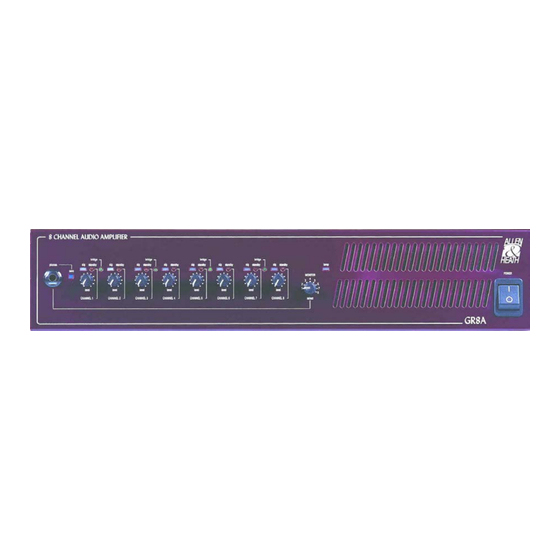
- Page 1 GR8A 8 Channel Amplifier USER GUIDE Publication AP4298...
-
Page 2: Warranty
Any changes or modifications to the equipment not approved by Allen & Heath could void the compliance of the equipment and therefore the users authority to operate it. GR8A User Guide AP4298 Issue 2. Copyright © 2001 Allen & Heath Limited. All rights reserved Manufactured in the United Kingdom by Allen &... -
Page 3: Table Of Contents
WARNING TO THE USER, INSTALLATION ENGINEER Allen & Heath warns that any unauthorised changes or modifications to the GR8A unit may invalidate the legal compliance of the unit and could void the user’s authority to operate the equipment. DO NOT REMOVE THE MAINS EARTH CONNECTION To ensure your safety the mains earth is connected to the chassis through the power lead. -
Page 4: Welcome To The Allen & Heath Gr8A
Welcome to the Allen & Heath GR8A The GR8A is one of a range of architectural sound products in the Allen & Heath Contractor Series. It is an 8 channel audio power amplifier designed to work with multi-output zoning mixers such as the Allen &... -
Page 5: Specifications
Control ......Switch common +15V to channel pin Desk mount ............ 440 x 380 x 92 Attenuation ..............-80dB Weight Inter-channel Crosstalk....relative to 60W into 4 ohms Unpacked ............12kg (26lbs) @ 1kHz..............< -70dB Packed ..............13kg (29lb @ 10kHz..............< -60dB GR8A U UIDE... -
Page 6: Front Panel Controls
Adjusts the monitor output to match the sensitivity of the connected headphones. This is an underpanel tamperproof switch to prevent accidental operation. Use a pen or similar pointed object to change its setting. The output level is increased when the switch is in its pressed position. GR8A U UIDE... -
Page 7: Rear Panel Controls And Connectors
BATTERY INPUT An emergency back-up supply such as battery or UPS is a common requirement for public announcement installations. GR8A has a 4way Phoenix type pluggable screw terminal input to connect two 24V DC batteries for back-up power in the event of a loss of mains supply. - Page 8 NORMAL 70V or 100V TRANSFORMER OPTION BRIDGED OUTPUT MODE switches The GR8A amplifier outputs can operate non- bridged (independently) or be bridged in pairs according to the setting of the tamperproof underpanel mode switches. Press the switch to select bridge mode using a pen or similar pointed object. This configures two amplifiers to work together into one speaker.
-
Page 9: Installation
INSTALLATION The GR8A can be rack or desk top mounted. It is supplied with rack ears and desk feet fitted. These may be removed according to the installation required. RACK MOUNT The GR8A fits into a 2U space in a standard 19” rack system. -
Page 10: Operation
Fan Cooling It is normal for the amplifier to run hot when it is working hard. The fan switches from off to slow to fast depending on internal temperature. The TEMP indicator lights green, amber or red accordingly. GR8A U UIDE... -
Page 11: Block Diagram
BLOCK DIAGRAM GR8A U UIDE...
Need help?
Do you have a question about the GR8A and is the answer not in the manual?
Questions and answers