Advertisement
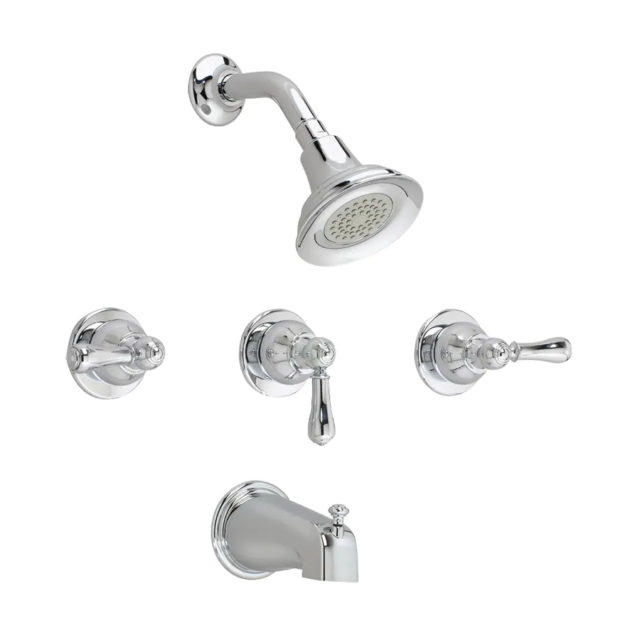
TWO HANDLE BATH/SHOWER SET
Thank you for selecting American-Standard...the benchmark
of fine quality for over 100 years.
To ensure that your installation proceeds smoothly--
please read these instructions carefully before you begin.
ROUGHING-IN DIMENSIONS
NOTE: NO CONCEALED PIPING FURNISHED
1-1/4 DIA HOLE
1/2" N.P .T.
SHOWER ARM
OPTIONAL TO FINISHED
FLOOR USUALLY
BETWEEN 65'' AND 78''
2" MIN.
3-1/4" MAX.
1/2" N.P .T. TO
SHOWER
CROSS
BRACE
1-3/4
1-3/4
TYP .
UNION INLET
1/2"-14 N.P .T.
4"
1/2" COPPER
BOTTOM OF TUB
Recommended Tools
Phillips Screwdriver
Plumbers' Putty or Caulking
*Hex key Supplied with Fitting
1
FINISHED
WALL
5 REF.
7 REF.
(2) 1-13/16" DIA. HOLES
FOR VALVES ON 8"
CENTERS (1) 1-13/16"
DIA. HOLE FOR CENTER
TRANSFER VALVE
18 OPTIONAL
1" MIN.
4
5-1/8"
REF.
TOP OF
TUB RIM
Flat Blade Screwdriver
Adjustable Wrench
Channel Locks
Installation
Instructions
7220.702
7221.722
7220.712
7221.732
7220.722
7222.702
7220.732
7222.712
7221.702
7222.722
7221.712
7222.732
ROUGHING-IN
SHOWER AND SPOUT
IMPORTANT: DO NOT REMOVE PLASTER GUARDS (2) UNTIL STEP 2.
Prepare water supplies per Roughing-in Dimensions. Apply sealing tape
to all threaded connections.
Install VALVE (1) at indicated height and depth. Make sure the outlet marked
"SHR" is pointing upward. Mount VALVE (1) to cross brace with wood screws.
Slip COUPLING NUT over supply pipe and thread UNION SWIVEL to pipe.
Connect HOT (6) water supply to LEFT valve inlet and COLD (7) water supply
to RIGHT valve inlet.
Prepare SHOWER RISER (4) and ELBOW (3). Connect to TOP outlet, marked
"SHR" of VALVE BODY (1).
Prepare TUB FILLER PIPE (8), ELBOW (10) and roughing-in COPPER PIPE (9).
Connect to BOTTOM outlet of VALVE BODY (1).
Add cross braces to wall structure and secure piping.
Cap NIPPLES (5) and COPPER PIPE (9). Open supply lines and check for leaks.
Remove PLASTER GUARDS (2). Use spline on end of PLASTER GUARD (2) to
open both VALVES and check for leaks.
Close both valves and turn off water supplies. Replace PLASTER GUARDS (2).
Finish wall construction.
5
"HOT"
"MAX WALL"
2
PLASTER
GUARD
6
Certified to comply with ANSI A112.18.1M
U.S. Patent No. 5,819,789
U S 6 0 4 0 6 R E V. 1. 2
Turn off hot and cold water
CAUTION
supplies before beginning.
3
4
CROSS
BRACE
(SHR)
1
"COLD"
SWIVEL
8
7
9
COUPLING
NUT
10
"COLD"
UNION
Advertisement
Table of Contents

Related Manuals for American Standard HAMPTON 7222.712


Summary of Contents for American Standard HAMPTON 7222.712
- Page 1 TWO HANDLE BATH/SHOWER SET Thank you for selecting American-Standard...the benchmark of fine quality for over 100 years. To ensure that your installation proceeds smoothly-- please read these instructions carefully before you begin. ROUGHING-IN DIMENSIONS NOTE: NO CONCEALED PIPING FURNISHED 1-1/4 DIA HOLE FINISHED 1/2"...
- Page 2 INSTALL TRIM (SHOWER AND TUB SPOUT) NOTE; PROTECT FINISH ON SHOWER AND TUB TRIM WHEN INSTALLING. Remove PLASTER GUARDS (1) from valve body by unthreading and pulling off. Remove rough-in nipple from shower elbow. Apply sealing tape to threads on both ends of SHOWER ARM (2) and install SHOWER ARM (2) with SHOWER ESCUTCHEON (3) into shower elbow.
- Page 3 M953569-YYY0A SHOWER HEAD 013307-YYY0A METAL CROSS HANDLE 021470-YYY0A INDEX 918428-0070A HANDLE SCREW 013311-YYY0A INDEX CAP 042692-0070A PORCELAIN CROSS HANDLE 916503-YYY0A LEVER HANDLE BASE 021470-YYY0A INDEX CAP 918428-0070A HANDLE SCREW 0060353-YYY0A PORCELAIN LEVER HANDLE 060409-YYY0A DIVERTER SPOUT (SLIP-ON) HOT LINE FOR HELP For toll-free information and answers to your questions, call: 1-800-442-1902 Weekdays 8:00 a.m.
Need help?
Do you have a question about the HAMPTON 7222.712 and is the answer not in the manual?
Questions and answers