
Subscribe to Our Youtube Channel
Related Manuals for Panasonic DMP-BDT230P; DMP-BDT230PC


Summary of Contents for Panasonic DMP-BDT230P; DMP-BDT230PC
- Page 1 ORDER NO.CHM1301002CE Blu-ray Disc Player DMP-BDT230P Model No. DMP-BDT230PC Colour (K).......Black Type Panasonic Corporation © 2013. Unauthorized copying and distribution is a violation of law.
-
Page 4: Table Of Contents
TABLE OF CONTENTS PAGE PAGE 1 Safety Precautions -----------------------------------------------5 1.1. General guidelines -----------------------------------------5 1.2. Caution for fuse replacement ---------------------------5 2 Warning --------------------------------------------------------------7 2.1. Prevention of Electrostatic Discharge (ESD) to Electrostatic Sensitive (ES) Devices ---------------7 2.2. Precaution of Laser Diode -------------------------------8 2.3. -
Page 5: Safety Precautions
1 Safety Precautions 1.1. General guidelines 1. When servicing, observe the original lead dress. If a short circuit is found, replace all parts which have been overheated or damaged by the short circuit. 2. After servicing, see to it that all the protective devices such as insulation barriers, insulation papers shields are properly installed. - Page 6 1.2.1. Micro Fuse conducting check This unit uses the Micro Fuse. Check the Micro Fuse conducting using the Tester at the check points below.
-
Page 7: Warning
2 Warning 2.1. Prevention of Electrostatic Discharge (ESD) to Electrostatic Sensitive (ES) Devices Some semiconductor (solid state) devices can be damaged easily by static electricity. Such components commonly are called Elec- trostatic Sensitive (ES) Devices. Examples of typical ES devices are integrated circuits and some field-effect transistors and semi- conductor "chip"... -
Page 8: Precaution Of Laser Diode
2.2. Precaution of Laser Diode... -
Page 9: Service Caution Based On Legal Restrictions
2.3. Service caution based on legal restrictions 2.3.1. General description about Lead Free Solder (PbF) The lead free solder has been used in the mounting process of all electrical components on the printed circuit boards used for this equipment in considering the globally environmental conservation. The normal solder is the alloy of tin (Sn) and lead (Pb). -
Page 10: Service Navigation
3 Service Navigation 3.1. Combination of Multiple Pressing on the Remote Control Press multi-buttons (in combination) on the remote control simultaneously for operations, such as initialization or service mode, etc. 3.2. Entering Special Modes with Combination of Multiple Pressing on the Remote Control Enter the following special modes by multiple pressing functions on the supplied remote control. - Page 11 3.2.1. Disclosure mode (Combination of multiple pressing: [OK] [Blue] [Yellow]) Press and hold [OK] [Blue] [Yellow] on the remote control simultaneously for 5 sec., then "00 RET" is displayed on FL display window. 3.2.2. Nondisclosure mode 1 (Combination of multiple pressing: [6] [7] [Yellow]) Press and hold [6] [7] [Yellow] on the remote control simultaneously for about 5 sec., then "50 RET"...
-
Page 12: How To Update Firmware
This unit has 2 updating method, one way to update via the internet, the other way to update using CD-R or USB device which is stored pre-downloaded firmware update file. 3.3.2.1. Updating firmware via the internet Occasionally, Panasonic may release updated firmware for this To update the firmware unit that may add or improve the way a feature operates. These Press [HOME] updates are available free of charge. - Page 13 3.3.2.2. Updating firmware using the USB device When updating firmware using USB device, perform following procedures. (When using CD-R instead of USB device, perform same procedures) 1. Download the latest firmware file of the unit The latest firmware required for version-up can be downloaded from "Support Information from NWBG/VDBG-PAVC" web-site in "TSN system".
-
Page 14: Specifications
4 Specifications *2: ISO9660 level1 or 2(except for extended formats), Joliet. This unit is compatible with multi-session. Power supply: AC120V, 60Hz This unit is not compatible with packet writing. Power consumption: Approx. 14W *3: UDF1.02 without ISO9660, UDF1.5 with ISO9660. in standby mode: Approx. - Page 15 Regional Code: DVD: #1 BD: Region A Dimensions: 430mm(W) [Approx. 16 15/16''(W)] 38mm(H) [Approx. 1 1/2''(H)] 179mm(D) [Approx. 7 1/16''(D)] Mass: Approx. 1.4 kg ( 3.08 lbs) Solder: This model uses lead free solder(PbF). Note: Specifications are subject to change without notice.
-
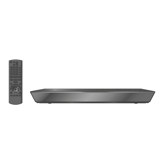
Page 16: Location Of Controls And Components
5 Location of Controls and Components... -
Page 17: Operating Instructions
6 Operating Instructions 6.1. Taking out the Disc from BD-Drive Unit when the Disc cannot be ejected by OPEN/CLOSE button 6.1.1. Forcible Disc Eject 1. Turn on the power, press and hold [OK], [B] and [Y] on the remote control at the same time for more than 5 seconds. "00 RET"... -
Page 18: Service Mode
7 Service Mode 7.1. Self-Diagnosis and Special Mode Setting 7.1.1. Self-Diagnosis Functions Self-Diagnosis Function provides information for errors to service personnel by “Self-Diagnosis Display” when any error has occurred. U** and F** are stored in memory and held. You can check latest error code by transmitting [0] [1] of Remote Controller in Service Mode. Automatic Display on FL will be cancelled when the power is turned off or AC input is turned off during self-diagnosis display is ON. - Page 19 Error Code Diagnosis contents Description Monitor Display Automatic FL display Initialization error When initialization error is detected after start- No display No display ing up main microprocessor, the power is turned off automatically. The event is saved in memory. Drive hardware error When drive unit error is detected, the event is No display No display...
- Page 20 7.1.2. Special Modes Setting Item FL display Key operation Mode name Description Rating password The audiovisual level setting password is While the unit is on, press and initialized to Level 8. hold [OK], [B] and [Y] on the remote control at the same time for more than 5 seconds.
- Page 21 Item FL display Key operation Mode name Description Aging Perform sequence of modes as * Aging Display following the then mode. While the unit is on, press and Description shown below continually. hold [5], [9] and [R] on the remote control at the same time for more than 5 seonds.
- Page 22 Item FL display Key operation Mode name Description Demonstration Ejection of the disc is prohibited. *When lock the tray. While the unit is on, press and lock/unlock The lock setting is effective until unlocking the hold [OK], [B] and [Y] on the remote tray and not released by Main unit control at the same time for more initialization of service mode.
- Page 23 7.1.3. Service Modes at a glance Information necessary for service can be displayed. Service mode setting: 1. Turn the power on. 2. Press the [5] [9] and [R] button simultaneously for five seconds, then [70 RET] is displayed on FL. 3.
- Page 24 Item Key operation FL display Mode name Description (Remote controller key) Laser Used Time Check laser used time (hours) of drive. Laser used time : BD Playback Press [4] [1] in service mode. Indication Laser used time : DVD Playback Laser used time : CD Playing (****) is the used time display in hour.
- Page 25 Item Key operation FL display Mode name Description (Remote controller key) BD Drive last error BD Drive error code display. 1. Error Number is displayed for 5 Press [4] [2] in service mode. seconds. 2. Time when the error has occurred is display for 5 seconds.
- Page 26 Item Key operation FL display Mode name Description (Remote controller key) In case that the maker cannot be 6. Disc maker ID is displayed for 5 identified, display is blackout. seconds.
- Page 27 7. Factor of drive error (hexadeci- mal) occurring is left displayed. 8. When the last error doesn't exist . PD Balance Measuring the PD balance. 1.Insert the Panasonic BD-VIDEO SL Disc(Ver 1.0/Ver 2.0) into the tray. (Incompatible with other media) 2.Press [4] [8].
- Page 28 Item Key operation FL display Mode name Description (Remote controller key) CEC (L) Output The CEC terminal low output of HDMI. Press [5] [6] in service mode. Manufacturing Date Read out the manufacturing date of the unit. Press [6] [1] in service mode. YY: Year MM: Month DD: Date...
- Page 29 Item Key operation FL display Mode name Description (Remote controller key) Delete the Error History Error History information stored on the unit is Press [9] [7] in service mode. deleted. Initialization of Error code Last Error Code information stored by timer is Press [9] [8] in service mode.
-
Page 30: Service Fixture & Tools
8 Service Fixture & Tools Part Number Description Compatibility RFKZ0216 Extension Cable (Digital P.C.B. - SD_USB P.C.B./ 23 Pin) Same as BDT220 Series RFKZ0327 Extension Cable (Digital P.C.B. - Power P.C.B./ 15 Pin) Same as BDT220 Series RFKZ03D01KS Lead Free Solder (0.3mm/100g Reel) Same as BDT220 Series RFKZ06D01KS Lead Free Solder (0.6mm/100g Reel) -
Page 31: Disassembly And Assembly Instructions
9 Disassembly and Assembly Instructions 9.1. Unit 9.1.1. Disassembly Flow Chart The following chart is the procedure for disassembling the casing and inside parts for internal inspection when carrying out the servicing. To assemble the unit, reverse the steps shown in the chart below. 9.1.2. -
Page 32: Front Panel
9.1.3. Top Case 9.1.4.2. Front Panel 1. Remove the 3 Screws (A) . 1. Unlock 7 tabs (A)-(G) turn. Pull with the Front Panel in the 2. Slide Top Case rearward and open the both ends at rear direction of your side. side of the Top Case a little and lift the Top Case in the direction of the arrows. -
Page 33: Rear Panel
9.1.6. SD_USB P.C.B. 9.1.8. Rear Panel 1. Remove the connector (A). 1. Remove the 2 Screws (A) and Screw (B). 2. Remove the 2 Screws (B). 2. Unlock 2 locking Tabs (C) to remove the Rear Panel. 9.1.9. Power P.C.B. 1. -
Page 34: Bd Drive
9.2. BD Drive Notes when attaching the tray: 1. Push Slide cam to the left side slightly, and make sure the tray band is between the two posts of Slide cam 9.2.1. Tray when attaching the tray. 1. Insert the Paper clips, etc. into the hole of the bottom side, and slide it to the direction of arrow until it can be. - Page 35 9.2.3. Slide Cam 4. Slide the Slid cam in the direction as shown, and then take the front post out of the slide cam track. 1. Perform the step “ Pulley Gear, Belt ”. 2. Remove the OPU FFC sheet from the mecha chassis. 3.
- Page 36 9.2.4. Drive Gear and Loading Motor 1. Perform the step “ Slide Cam ”. 2. Remove the Drive Gear. 3. Loosen the hooks, and remove the Loading Motor Unit and the SW Ass'y.
- Page 37 9.2.5. Grease...
-
Page 38: Disassembly From The Traverse Unit, Assembly Of The Optical Pick-Up Unit, And Precautions On Esd-Preventive
9.3. Disassembly from the traverse 3. Remove the Mid base. unit, assembly of the optical pick-up unit, and precautions on ESD-preventive 9.3.1. Disassemly 1. Before removing the optical pick-up unit, please apply an ESD prevention bag(RPFC0114) to the OPU FFC, and weld the short-circuit solder. - Page 39 9.3.2. Assembly 4. Press down the handle A of the two springs, and remove the shaft with OPU. 1. Insert the shaft into the shaft hole of the base, install the OPU to the auxiliary shaft, and then attach the nut piece unit onto the screw stem.
- Page 40 4. Insert FFC, and desolder the solder spot. a. Use the iron head with an angle as shown in Fig,remove the solder in the direction as shown. b. Set the temperature of iron below 350°C. c. When using the iron head,do not apply a force more than 1N to the pad.
- Page 41 9.3.3. How to Clean the Lens of Optical Pick-UP...
-
Page 42: Adjustment Of Bd Drive
9.4. Adjustment of BD Drive 9.4.1. Repair Flowchart... - Page 43 9.4.2. Adjustment 9.4.2.1. [Drive] Input Engineering Adjusted Value([7] [2]) 1. Input [7] [2] with the remote control's numeral keys in the service mode. The TV display "DQR__"(__is blank)at this time.Engineering Adjusted Value display is in the input state. 2. Input Engineering Adjusted Value with remote control: The TV is displaying the input numeric from the left.(Use "*"...
-
Page 44: Measurements And Adjustments
10 Measurements and Adjustments 10.1. Service Positions NOTE: For description of the disassembling procedure, see the section 9. 10.1.1. Checking and Repairing of Power P.C.B. - Page 45 10.1.2. Checking and Repairing of BD Drive and Digital P.C.B.
-
Page 46: Caution For Replacing Parts
The Panasonic RAM disc should be recognized. Perform playback for one minute using the RAM disc. No abnormality should be seen in the picture, sound or operation. *Panasonic DVD-RAM disc should be used when recording and playback. Perform playback for one minute using the BD-Video disc. -
Page 47: Block Diagram
11 Block Diagram 11.1. Overall Block Diagram TRAVERSE MECHANISM UNIT IC51001 OPTIACL PICK-UP UNIT IC53003 IC55003 DIGITAL AUDIO OUT LASER DIODE (OPTIAL) BEAM EXPANDER (JK56301) HDMI FOCUS COIL TERMINAL SERVO CONTROLLER/ TRACKING COIL OPTICAL DISC CONTROLLER/ MOTOR DRIVE AV DECODER/ SYSTEM CONTROLLER TRAVERSE MOTOR... -
Page 48: Power Supply Block Diagram
11.2. Power Supply Block Diagram MAIN P.C.B. T1001 VA1001,L1001 D1006, C1014 POWER TRANSFORMER AC SOCKET P1001 F1001 SURGE SUPPRESSOR RECTIFIER AND SURGE ABSOBER IC1021 (SWITCHING IC) D1022 D1110 PW_X_SW12.2V P1102 P58001 FB/OLF DIGITAL P.C.B. D1111 PW_X_SW5.1V P1102 P58001 13,14,15 Q1022 (FEED BACK) IC1103 (ERROR VOLTAGE DET.) -
Page 49: Digital P.c.b. Regulator Block Diagram
11.3. Digital P.C.B. Regulator Block Diagram IC58200 (REG.1.2V) PW_X_SW5.1V FROM P1102 P58001 MAIN P.C.B. PW_SW1.2V 13,14,15 IC51001- DVCC12_K,AVDD12 FROM FLASH_IR_VFD P_ON_H QR51001 IC51001- AH25 SECTION IC58400 (REG.3.3V) PW_3.3V IC51001- AVDD33 VOUT 1 IC55003- 18 IC51301- 12 13 IC58600 (REG.3.3V) PW_SD_3.3V P59001- VOUT 3 IC56301... -
Page 50: Digital (Back End Section) Block Diagram
11.4. Digital (Back End Section) Block Diagram IC51001 (PEAKS-PRO3) POWER P.C.B. D1176 SD_USB P.C.B. T1101 DISPLAY POWER P6802 SWITCHING SD CARD SLOT Q1170 TRANSFOMER PW_X_SW12.2V DAT0 SD_D0_B P6801 P59001 C3 GPIO13 DAT1 P6801 P59001 SD_D1_B D1173 A1 GPIO14 DAT2 SD_D2_B P6801 P59001 C1 GPIO15... -
Page 51: Digital (Front End Section) Block Diagram
11.5. Digital (Front End Section) Block Diagram FOCUS ERROR SIGNAL TRACKING ERROR SIGNAL MOTOR DRIVE SIGNAL RF SIGNAL IC51001 SODC (OPTICAL DISC CONTROLLER) OPTICAL PICK-UP/TRAVERSE P55001 RFIN BD/DVD RF SIGNAL RFIP DVD FOCUS AND TRACKING SIGNAL FO/TR ACTUATOR SPINDLE LASER MOTOR BD FOCUS AND TRACKING SIGNAL DETECTOR... -
Page 52: Wiring Connection Diagram
12 Wiring Connection Diagram 12.1. Interconnection Schematic Diagram P55001 NC/GND NC/GND P1001 SEL_CD SEL_CD SEL_DVD SEL_DVD TEMP TEMP LDI_DVD LDI_DVD P58001 P1102 LDI_CD LDI_CD LDI_BD LDI_BD PW_X_SW3R3V PW_X_SW3R3V KEY3(PLAY) KEY3(PLAY) GND1 GND1 KEY2(STOP) KEY2(STOP) SEL_BD SEL_BD KEY1(EJECT) KEY1(EJECT) FL_CK FL_CK VCC_+5PD VCC_+5PD VREF_PD... -
Page 53: Appendix Information Of Schematic Diagram
13 Appendix Information of Schematic Diagram 13.1. Waveform Chart NOTE: Circuit waveform described herein shall be regarded as reference information when probing defect point, because it may differ from an actual measuring value due to difference of Measuring instrument and its measuring condition and product itself. 13.1.1. - Page 54 Model No. : DMP-BDT230P/DMP-BDT230PC SCHEMATIC DIAGRAM NOTICE...
- Page 55 Model No. : DMP-BDT230P/DMP-BDT230PC PART LIST NOTICE...
- Page 56 Model No. : DMP-BDT230P/DMP-BDT230PC ABBREVIATIOM...
- Page 57 Model No. : DMP-BDT230P/DMP-BDT230PC POWER SECTION(POWER P.C.B.)
- Page 58 Model No. : DMP-BDT230P/DMP-BDT230PC FL SECTION(POWER P.C.B.)
- Page 59 Model No. : DMP-BDT230P/DMP-BDT230PC SD_USB SECTION(SD_USB P.C.B.)
- Page 60 Model No. : DMP-BDT230P/DMP-BDT230PC AUDIO DAC SECTION(DIGITAL P.C.B.)
- Page 61 Model No. : DMP-BDT230P/DMP-BDT230PC ETHER USB SD SECTION(DIGITAL P.C.B.)
- Page 62 Model No. : DMP-BDT230P/DMP-BDT230PC DIGITAL NET SECTION(DIGITAL P.C.B.)
- Page 63 Model No. : DMP-BDT230P/DMP-BDT230PC DDR3 CH A SECTION(DIGITAL P.C.B.)
- Page 64 Model No. : DMP-BDT230P/DMP-BDT230PC DDR3 CH B SECTION(DIGITAL P.C.B.)
- Page 65 Model No. : DMP-BDT230P/DMP-BDT230PC FLASH IR VFD SECTION(DIGITAL P.C.B.)
- Page 66 Model No. : DMP-BDT230P/DMP-BDT230PC HDMI AV SECTION(DIGITAL P.C.B.)
- Page 67 Model No. : DMP-BDT230P/DMP-BDT230PC HDMI SUB SECTION(DIGITAL P.C.B.)
- Page 68 Model No. : DMP-BDT230P/DMP-BDT230PC FE SECTION(DIGITAL P.C.B.)
- Page 69 Model No. : DMP-BDT230P/DMP-BDT230PC POWER P.C.B.(COMPONENT SIDE)
- Page 70 Model No. : DMP-BDT230P/DMP-BDT230PC POWER P.C.B.(FOIL SIDE)
- Page 71 Model No. : DMP-BDT230P/DMP-BDT230PC SD_USB P.C.B.(COMPONENT SIDE)
- Page 72 Model No. : DMP-BDT230P/DMP-BDT230PC SD_USB P.C.B.(FOIL SIDE)
- Page 73 Model No. : DMP-BDT230P/DMP-BDT230PC DIGITAL P.C.B.(COMPONENT SIDE)
- Page 74 Model No. : DMP-BDT230P/DMP-BDT230PC DIGITAL P.C.B.(FOIL SIDE)
- Page 75 Model No. : DMP-BDT230P/DMP-BDT230PC Parts List Ref. Change Safety Part No. Part Name & Description Q'ty Remarks ■ VEP71300C POWER P.C.B. (RTL) E.S.D. C1005 F1B2G102A024 100V 1000P C1006 F1B2G102A024 100V 1000P C1009 F0CAF104A150 250V 0.1U C1014 F2B2D4700003 200V 47U C1018 F1B2G102A024 100V 1000P C1021...
- Page 76 Model No. : DMP-BDT230P/DMP-BDT230PC Parts List Ref. Change Safety Part No. Part Name & Description Q'ty Remarks R1123 D0GD682JA052 1/8W 6.8K R1171 D0GB472JA065 1/10W 4.7K R1172 D0GB472JA065 1/10W 4.7K R1173 D0GB562JA065 1/10W 5.6K R1174 D0GB470JA065 1/10W 47 R1176 D0GB182JA065 1/10W 1.8K R7001 D0GD100JA052 1/8W 10...
- Page 77 Model No. : DMP-BDT230P/DMP-BDT230PC Parts List Ref. Change Safety Part No. Part Name & Description Q'ty Remarks C52020 F1G1A1040006 10V 0.1U C52021 F1G1A1040006 10V 0.1U C52022 F1G1A1040006 10V 0.1U C52023 F1G1A1040006 10V 0.1U C52024 F1G1A1040006 10V 0.1U C52025 F1G1A1040006 10V 0.1U C52026 F1G1A1040006 10V 0.1U C52027 F1G1A1040006...
- Page 78 Model No. : DMP-BDT230P/DMP-BDT230PC Parts List Ref. Change Safety Part No. Part Name & Description Q'ty Remarks C55001 F1G1E102A086 25V 1000P C55016 F1G1A104A012 10V 0.1U C55017 F1J1C475A059 16V 4.7U C55018 F1G1A104A012 10V 0.1U C55026 F1H0J2250008 6.3V 2.2U C55029 F2G1E470A066 25V 47P C55030 F1G1A104A012 10V 0.1U C55031 F1G1E1040001...
- Page 79 Model No. : DMP-BDT230P/DMP-BDT230PC Parts List Ref. Change Safety Part No. Part Name & Description Q'ty Remarks C56523 F1G1A1040006 10V 0.1U C56524 F1G1A1040006 10V 0.1U C56525 F1G1A1040006 10V 0.1U C58100 F1H1A105A028 10V 1U C58101 F1H1A105A028 10V 1U C58112 F1H1C104A071 16V 0.1U C58113 F1H1E223A050 25V 0.022U C58120 F1H1A105A028...
- Page 80 Model No. : DMP-BDT230P/DMP-BDT230PC Parts List Ref. Change Safety Part No. Part Name & Description Q'ty Remarks JK56301 K1FY119E0025 JACK HDMI L55001 G1C100KA0101 COIL L55002 G1C220MA0291 COIL L55003 G1C100KA0101 COIL L56301 J0MAB0000241 FILTERS FOR EMI/ EMC L56302 J0MAB0000241 FILTERS FOR EMI/ EMC L58200 G1C3R3ZA0367 COIL L58300 G1C3R3ZA0367...
- Page 81 Model No. : DMP-BDT230P/DMP-BDT230PC Parts List Ref. Change Safety Part No. Part Name & Description Q'ty Remarks R55029 D0GA121JA023 1/16W 120 R55030 D0GA121JA023 1/16W 120 R55031 D0GA121JA023 1/16W 120 R55040 ERJ8RQFR39V 1/8W 39 R55041 ERJ8RQFR39V 1/8W 39 R55050 D0GA103JA023 1/16W 10K R55051 D0GB913JA065 1/10W 91K R55060 D0GA562JA023...
- Page 82 Model No. : DMP-BDT230P/DMP-BDT230PC Parts List Ref. Change Safety Part No. Part Name & Description Q'ty Remarks RX58120 D1HY4734A012 RESISTOR-RESISTOR RX59602 D1HY3304A012 RESISTOR-RESISTOR RX59603 D1HY1034A012 RESISTOR-RESISTOR RX59604 D1HY1034A012 RESISTOR-RESISTOR T59201 EXC24CE900U TRANSFORMER T59401 G5BYC0000040 TRANSFORMER X51001 H0J270500151 OSCILLATOR ZA51000 RMY0409 RADIATOR SHEET ■...
- Page 83 Model No. : DMP-BDT230P/DMP-BDT230PC Exploded View...
- Page 84 Model No. : DMP-BDT230P/DMP-BDT230PC Mechanism View...
- Page 85 Model No. : DMP-BDT230P/DMP-BDT230PC Packing View...
- Page 86 Model No. : DMP-BDT230P/DMP-BDT230PC Parts List Ref. Change Safety Part No. Part Name & Description Q'ty Remarks ■ CASING VXY2171T BD DRIVE 1 ADJ VEP71300C POWER P.C.B. 1 (RTL) E.S.D. RFKB76327BT DIGITAL P.C.B. 1 E.S.D. ADJ BDT230P RFKB76327BCT DIGITAL P.C.B. 1 E.S.D.
- Page 87 Model No. : DMP-BDT230P/DMP-BDT230PC Parts List Ref. Change Safety Part No. Part Name & Description Q'ty Remarks 119-9 VMG1966 DAMPER 119-10 VMG1966 DAMPER ■ ACCESSORY K2CB2CB00022 AC CORD N2QAYB000874 REMOTE CONTROL UNIT RPFC0119-1 POLYETHYLENE BAG VQT4V26 OPERATING INSTRUCTIONS 1 (IA) VQT4V27 OPERATING INSTRUCTIONS 1 (IB) BDT230PC...
Need help?
Do you have a question about the DMP-BDT230P; DMP-BDT230PC and is the answer not in the manual?
Questions and answers