
Related Manuals for Newave PowerValue 11


Summary of Contents for Newave PowerValue 11
-
Page 1: User Manual
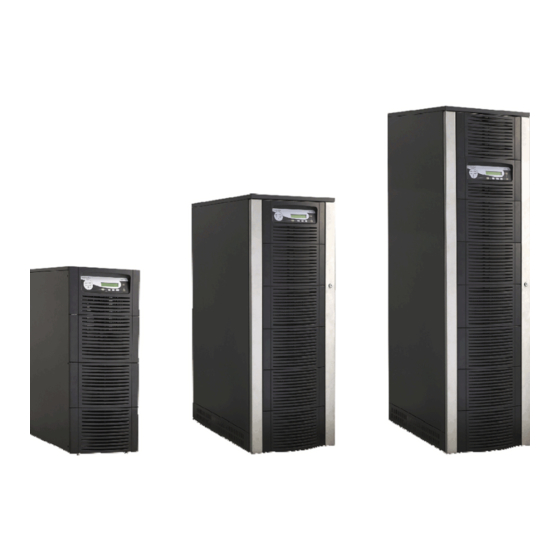
PowerValue 11 and 31 User Manual 11 and 31 OWER ALUE Single-phase UPS System 7.5 - 20kVA CABINET B CABINET C CABINET A Newave_OPM_PV11_PV31 _GB_250805.doc Page 1... -
Page 2: Table Of Contents
CONTENTS SAFETY ..............................4 DESCRIPTION............................5 RELIABILITY AND QUALITY STANDARDS..................5 POWERVALUE MODELS........................5 WARRANTY............................5 EXTENDED WARRANTY ........................6 INSTALLATION............................7 INTRODUCTION..........................7 3.1.1 Receipt of the UPS ........................7 3.1.2 Nameplate............................7 UNPACKING ............................7 BATTERIES ............................7 STORAGE............................ - Page 3 4.3.2 Main Menu Screen........................26 4.3.3 Event Log Screen ........................26 4.3.4 Measurements Screen......................... 26 4.3.5 Commands Screen ........................27 4.3.6 UPS Data ............................. 27 4.3.7 Set-Up User ..........................27 4.3.8 Set-Up Service..........................28 OPERATING MODES ........................29 4.4.1 Mode "ON LINE" (INVERTER MODE) ..................29 4.4.2 Mode "OFF-LINE"...
-
Page 4: Safety
Fax. +41 91 840 12 54 e-mail: info@newave.ch www.newave.ch NEWAVE SA WILL ASSUME NEITHER RESPONSIBILITY NOR LIABILITY DUE TO INCORRECT OPERATION OR MANIPULATION OF THE UPS. HIGH LEAKAGE CURRENT! MAKE SURE THAT THE EARTHING IS CARRIED OUT CORRECTLY BEFORE YOU CONNECT THE MAINS POWER SUPPLY! THE POWERVALUE 7.5-20 kVA IS CLASS A - UPS-PRODUCT (ACCORDING TO EN... -
Page 5: Description
NEWAVE or of the authorized service centre. NEWAVE is not liable for any costs, such as loss of profits or revenue, loss of equipment, loss of data or software, cost of substitutes, claims by third parties or otherwise. -
Page 6: Extended Warranty
NEWAVE will not knowingly sell its products for use in such applications unless it receives in writing assurances satisfactory to NEWAVE that the risks of injury or damage have been minimized, the customer assumes all such risks and the liability of NEWAVE is adequately protected under the circumstances. -
Page 7: Installation
The battery life depends very much on the ambient temperature. A temperature range between +18° and +23°C will achieve the optimum battery life. If the UPS is delivered without batteries, NEWAVE is not responsible for any damage or malfunctioning caused to the UPS by incorrect wiring Newave_OPM_PV11_PV31 _GB_250805.doc Installation... -
Page 8: Storage
3.4 STORAGE 3.4.1 If you plan to store the UPS prior to use, keep the UPS unpacked in a dry, clean and cool storage room with an ambient temperature between (+5 °C to +40°C) and humidity of less than 90%. If the packing container is removed protect the UPS from dust. -
Page 9: Cabling
3.6 CABLING POWERVALUE cabling must be achieved in accordance with one of the three following configurations: POWERVALUE 7.5, 10 and 12kVA with SINGLE PHASE INPUT (Cabinet A) POWERVALUE 7.5, 10 and 15kVA with THREE PHASE INPUT (Cabinet A) POWERVALUE 7.5, 10, 15 and 20kVA with THREE PHASE INPUT (Cabinet B) NOTE : Before you start cabling your UPS make sure you have determined... -
Page 10: Connection Of The Mains Supply
Connecting sequence of earthing wire (see Figure 1): 1) Unscrew both screws of the terminal cover plate (4) and remove the terminal cover plate. 2) Carefully remove terminal cover plate (4) and don’t pull on the earthing wire (5). If necessary the earthing wire may be removed during the cabling. -
Page 11: Dual Input Feed
3.6.7 Dual Input Feed NOTE: In the standard version POWERVALUE comes with SINGLE INPUT FEED. If DUAL INPUT FEED is required please contact your next service office before performing any cabling. 3.6.8 Preparation for the Output Cabling Before you start connecting the loads, ensure that the sum of the indicated UPS-Systems rated powers (OUTPUT POWER) on the nameplates (on the front side of the UPS-Systems) is equal to or larger than the total load requirements. -
Page 12: Output Cabling
3.6.10 Output Cabling To achieve correct Output Cabling see Figure 1. OUTPUT CABLE UPS TERMINAL Phase L1 NEUTRAL EARTH Under the connection terminal of the UPS there is a cable-fixing rail to ensure that the cables have been fastened properly. 3.6.11 How to fix the POWERVALUE to the floor After having performed the connections screw the terminal cover plate back on the UPS. - Page 13 Cabinet B and C Elements: Rectifier Line Fuse Bypass Line Fuse Battery Fuse Cabinet A Maintenance Bypass Output Switch Smart Port-RS232 (SUB-D9P/F) X1-X21 Dry Port-volt-free contacts on terminal block (see chapter 3.8.2) SNMP SNMP FA1 (A) FA2 (A) FA3 (A) X1-X21 7,5kVA 50 A...
-
Page 14: Cabling Of Powervalue 7.5, 10, 12, 15 And 20Kva With Three Phase Input
3.6.12 Cabling of POWERVALUE 7.5, 10, 12, 15 and 20kVA with THREE PHASE INPUT NOTE: Before you start cabling your UPS POWERVALUE make sure you have determined the correct Version with the right POWER and INPUT CONFIGURATION. NOTE: THIS UPS COMES (STANDARD VERSION) WITH A SINGLE CABLE FEED (FOR RECTIFIER AND BYPASS). -
Page 15: Connection Of The Mains Supply
Under the connection terminal of the UPS there is a cable-fixing rail to ensure that the cables have been fastened properly 3.6.16 Connection of the Mains Supply After the UPS has been unpacked and brought to its final position the authorized technician may start with the cabling. -
Page 16: Preparation For The Output Cabling3
3.6.19 Preparation for the Output Cabling3 Before you start connecting the loads, ensure that the sum of the indicated UPS-Systems rated powers (OUTPUT POWER) on the nameplates (on the front side of the UPS-Systems) is equal to or larger than the total load requirements. The output of the UPS must be fitted with circuit breakers or other kind of protection. -
Page 17: Output Cabling
3.6.21 Output Cabling To achieve correct Output Cabling see Terminal Block in Figure 3. For output cabling connect output cable to UPS Terminal according to following Output to UPS terminal block correlation. OUTPUT CABLE UPS TERMINAL Phase L1 NEUTRAL EARTH Under the connection terminal of the UPS there is a cable-fixing rail to ensure that the cables have been fastened properly 3.6.22 How to fix the POWERVALUE to the floor... - Page 18 Cabinet A Elements: Rectifier Line Fuse Bypass Line Fuse Battery Fuse SNMP Maintenance Bypass Output Switch Smart Port-RS232 (SUB-D9P/F) X1-X21 Dry Port-volt-free contacts on terminal block (see chapter 3.8.2) X1-X21 Note: the number of fans depend on the power of the UPS. FA1 (A) FA2 (A) FA3 (A)
- Page 19 Cabinet B and C Elements: Rectifier Line Fuse Bypass Line Fuse Battery Fuse Maintenance Bypass Output Switch Smart Port-RS232 (SUB-D9P/F) X1-X21 Dry Port-volt-free contacts on terminal block (see chapter 3.8.2) FA1 (A) FA2 (A) FA3 (A) 7,5kVA 32 A 50 A 30 A SNMP (10x38)
-
Page 20: Connection Of External Batterîes For Ups Powervalue
CONNECTION OF EXTERNAL BATTERIES FOR UPS POWERVALUE For the standard POWERVALUE products no external battery cabinets are provided. Longer autonomies are achieved by using one of the higher UPS Cabinets B or C which have more space for batteries than the Cabinet A. The PowerValue UPS is delivered with an optional external batteries connection terminals only if it has been ordered without batteries. -
Page 21: Interfacing
3.8 INTERFACING The PowerValue is provided with two ports: • SMART PORT (Serial RS 232); • DRY PORT (volt-free contacts); 3.8.1 SMART PORT (Serial RS 232) The SMART PORT JD1 is an intelligent RS 232 serial port that allows the UPS to be connected to a computer. -
Page 22: Dry Port (Volt-Free Contacts)
3.8.2 DRY PORT (volt-free contacts) Description: The DRY PORT may be used for: • Connection of remote shutdown facilities (see paragraph 7.2); • Connection of Remote Status Panel (see paragraph 7.3); • Provision of signals for the automatic and orderly shutdown of servers •... -
Page 23: Operation
Any PowerValue UPS system not commissioned by a NEWAVE field service engineer or authorized service centre must be considered an electrical hazard and NEWAVE accepts no responsibility for its safe operation or the safety of any personnel. Additionally, the manufacturer’s... -
Page 24: Led Indicators
4.2.2 LED Indicators The mimic diagram serves to indicate the general status of the UPS. The LED-indicators show the power flow status and in the event of mains failure or load transfer from inverter to bypass and vice- versa. The corresponding LED-indicators will change colours from green (normal) to red (warning). The LED’s LINE 1 (rectifier) and LINE 2 (bypass) indicate the availability of the mains power supply. -
Page 25: On/Off Start-Up And Shutdown Buttons
4.2.4 ON/OFF Start-up and Shutdown Buttons By pressing simultaneously both ON/OFF Buttons on the Control Panel the UPS may be switched on or shutdown. This is to prevent accidental start-up or shutdown of the UPS. The two main ON/OFF buttons are also used as a security LOAD–OFF-switch, making it possible to quickly disconnect the load from the UPS in emergency situations when a competent technician working on the UPS is in danger or if the UPS has some kind of anomaly. -
Page 26: Description Of The Lcd
4.3 DESCRIPTION OF THE LCD 4.3.1 Status Screens DESCRIPTION LCD-DISPLAY Load is protected by UPS power (load is supplied LOAD by inverter(Normal Operation) PROTECTED Load is not protected by UPS power it is supplied LOAD by mains power (load on bypass) NOT PROTECTED Load supply completely interrupted. -
Page 27: Commands Screen
Bypass Voltage BYPASS VOLTAGE (V) Output Voltage OUTPUT VOLTAGE (V) Output Current OUTPUT CURRENT (A) 00.00 00.00 00.00 Active Output Power ACTIVE POWER (KW) 00.00 00.00 00.00 Reactive Output Power REACTIVE POWER (kVAr) 00.00 00.00 00.00 Apparent Output Power APPARENT POWER (KVA) 00.00 00.00 00.00... -
Page 28: Set-Up Service
Set-up battery test SET BATTERY TEST SET GENERATOR OP. DAY OF MONTH (1-31) HOUR OF DAY (1-24) REPETITIVE (Y/N) YES/NO Set-up operation with Gen-Set SET GENERATOR OP. NO MORE SETTINGS BATT.CHARGE LOCK YES/NO BYPASS LOCK YES/NO 4.3.8 Set-Up Service DESCRIPTION LCD-DISPLAY SET-UP SERVICE This Menu is reserved for authorized service... -
Page 29: Operating Modes
The "Bypass-Mode”, is recommended only if the loads can tolerate interruptions of 3-5 ms (transfer time from Bypass Mode to ON-LINE Mode). In order to provide the load with maximum protection NEWAVE always recommends that the load be supplied by the inverter (ON-LINE-Mode). -
Page 30: Maintenance Bypass" - Mode
4.4.3 "MAINTENANCE BYPASS" - Mode The Maintenance Bypass Mode is performed by means of the MANUAL BYPASS SWITCH on the rear for cabinet A and front for cabinet B/C of the UPS: POSITION OF EFFECT SWITCH Bypass-Switch Closed (Load supplied directly from mains) LCD-indication: “MANUAL BYP IS CLOSED”... -
Page 31: Start-Up Procedure
4.5 START-UP PROCEDURE ALL THE OPERATIONS IN THIS SECTION MUST BE PERFORMED BY AUTHORISED ELECTRICIANS OR BY QUALIFIED INTERNAL PERSONNEL. Situation of UPS-System before switching it on: 1. The fuses for the supply of UPS-System in the Input Distribution Board on site are open. 2. - Page 32 On LCD: “MANUAL BYP IS CLOSED” will appear and the LED-indicator will indicate as shown bellow: LED Indicator Colour LINE 1 Green LINE 2 Green BYPASS Green INVERTER BATTERY Green NOTE: Your UPS in now on manual bypass and the load is not protected 9.
-
Page 33: Shutdown Procedure
4.6 SHUTDOWN PROCEDURE ALL THE OPERATIONS IN THIS SECTION MUST BE PERFORMED BY AUTHORISED ELECTRICIANS OR BY QUALIFIED INTERNAL PERSONNEL. The PowerValue UPS may be shutdown completely if the load does not need input power for an extended period of time. It may be switched to Maintenance Bypass Mode for service or maintenance purposes, or transferred to the OFF-LINE Mode if the load does not need the highest degree of protection. -
Page 34: Load Transfer: From Inverter Operation To Maintenance Bypass
4.7 LOAD TRANSFER: FROM INVERTER OPERATION TO MAINTENANCE BYPASS If it is necessary to perform service or maintenance on the UPS it is possible to transfer the UPS to MAINTENANCE BYPASS. BEFORE YOU SWITCH THE MAINTENANCE BYPASS TO POSITION «ON», MAKE SURE THAT THE LOAD HAS BEEN TRANSFERRED TO MAINS SUPPLY (OFF-LINE MODE) ALL THE OPERATIONS IN THIS SECTION MUST BE PERFORMED BY AUTHORISED ELECTRICIANS OR BY QUALIFIED INTERNAL PERSONNEL. -
Page 35: Load Transfer: From Maintenance Bypass To Inverter Operations
4.8 LOAD TRANSFER: FROM MAINTENANCE BYPASS TO INVERTER OPERATIONS This procedure describes the sequence of operations to be done in order to restart the UPS and restore ON-LINE mode (Load on Inverter). ALL THE OPERATIONS IN THIS SECTION MUST BE PERFORMED BY AUTHORISED ELECTRICIANS OR BY QUALIFIED INTERNAL PERSONNEL. -
Page 36: Maintenance
UPS. Preventative maintenance inspections involve working inside the UPS, which contains hazardous AC and DC voltages. Only NEWAVE trained or agreed service personnel and authorised field service engineers are fully aware of all of the hazardous areas within the UPS. -
Page 37: Troubleshooting
6 Troubleshooting 6.1 ALARMS In the event of an alarm condition the red LED-Indicator “Alarm” and the audible alarm will turn on. In this case proceed as follows: 1. Silence the audible alarm by pressing the button "Reset". 2. Identify the cause of the alarm condition by means of the EVENT LOG in the MAIN menu. 3. -
Page 38: Options
7 Options 7.1 INTRODUCTION The UPS PowerValue is provided with the following accessories: • REMOTE SHUTDOWN FACILITIES; • REMOTE SIGNALLING PANEL (RSP); • GENERATOR ON FACILITIES; • WAWEMON SOFTWARE FOR AUTOMATIC SHUTDOWN AND MONITORING; • SNMP INTERFACES FOR NETWORK MANAGEMENT AND REMOTE MONITORING. 7.2 REMOTE EMERGENCY FACILITIES The emergency stop facility must use a normally closed contact, which opens to operate the emergency stop sequence. -
Page 39: Remote Signalling Panel (Rsp)
7.3 REMOTE SIGNALLING PANEL (RSP) The optional Remote Status Panel (RSP) may be used to display UPS status information up to a distance of 100m. LINE LOAD BATT. LINE BYPASS Remote Signalling Panel INDICATOR INDICATOR STATUS MEANING LINE GREEN Mains available Mains not available BATTERY GREEN... -
Page 40: How To Connect The Remote Signaling Panel (Rsp)
7.3.1 How to Connect the Remote Signaling Panel (RSP) • Provide a 0,7.5 mm , shielded cable (max 100 meters); • Do not connect shielding; • On one end of the cable prepare the connectors for a Terminal block connection •... -
Page 41: Wavemon Shutdown And Management Software
The UPS software will react automatically in such a case and shutdown the operating system. NEWAVE has found it important to have a complete solution for its UPS and is able to offer a wide range of monitoring/remote controls for assuring the maximum protection degree to the NEWAVE customers. - Page 42 (supervisor). In order to be managed, a NEWAVE UPS can be integrated into a network in two ways: 1. By means of the server which is being powered by the UPS and is integrated in the network. In most of the cases the server is used as sub-agent and you only need the Wavemon software without any SNMP Adapter.
-
Page 43: Snmp Card/Adapter For Network Management /Remote Monitoring
7.6 SNMP CARD/ADAPTER FOR NETWORK MANAGEMENT /REMOTE MONITORING The Simple Network Management Protocol (SNMP) is a worldwide-standardized communication- protocol. It is used to monitor any device in the network via simple control language. The UPS- Management Software also provides its data in this SNMP format with its internal software agent. The operating system you are using must support the SNMP protocol. -
Page 44: Technical Specifications
8 Technical Specifications Newave_OPM_PV11_PV31 _GB_250805.doc Technical Specifications Page 44...
Need help?
Do you have a question about the PowerValue 11 and is the answer not in the manual?
Questions and answers