
Related Manuals for Newave 1000-3000VA


Summary of Contents for Newave 1000-3000VA
-
Page 1: User Manual
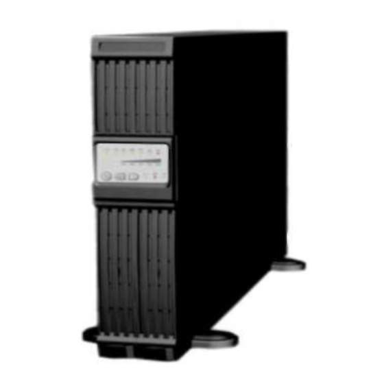
User Manual 1000-3000VA (single phase In/Output) Intelligent True On-Line Uninterruptible Power Supply (UPS) For Corporate & IT User Installation Guide... - Page 2 Intelligent True On-Line Uninterruptible Power Supply (UPS) For Corporate & IT User Installation Guide...
-
Page 3: Table Of Contents
TABLE OF CONTENTS Standard Unit Installation Guide Important – Please read carefully prior to installation Storage Instruction Product Introduction General Characteristics Special Features UPS Functional Descriptions UPS Front Panel Display Descriptions Real Panel Descriptions Operating Modes & Voltage System Configurations 3.3.1 System Configuration Settings 3.3.2... -
Page 4: Specifications
10.3 Chapter 3: Installation and Operation 10.3.1 Unpacking 10.3.2 Selecting Installation Position 10.3.3 Installation Instructions 10.3.4 Rack Mount installation 10.3.5 Storage Instruction 10.3.6 Replacing the Battery 10.3.7 Specifications 10.3.8 Recycling the Used battery 11 Technical Specifications... -
Page 5: Standard Unit Installation Guide
1 Standard Unit Installation Guide 1.1 Important – Please read carefully prior to installation 1. Though this UPS is designed for easy Plug-and-Play installation, it is advisable to engage qualified Electrical Engineer or trained technical personnel to commission or repair the UPS. 2. -
Page 6: Product Introduction
2 Product Introduction 2.1 General Characteristics 1. True online technology continuously supplies your critical device with a stable, regulated, transient-free pure sine wave AC Power. 2. High-efficiency PWM sine-wave topology yields an excellent overall performance. The high crest factor of the inverter handles all high in-rush current loads without the need to upgrade the power rating. -
Page 7: Ups Functional Descriptions
3 UPS Functional Descriptions 3.1 UPS Front Panel Display Descriptions Control Keypads Symbols Functional Descriptions 1. ON UPS Power-On Switch 2. OFF UPS Power-Off Switch a. Command the UPS to perform self-testing 3.Self-Test(Alarm Silence) b. Alarm Silence - To mute the alarm buzzer (Do not press & hold for > 1 sec) LED Indicators Symbols Functional Descriptions LED illuminated indicates utility voltage within tolerance... -
Page 8: Real Panel Descriptions
3.2 Real Panel Descriptions 1. USB Port 2. RS232 Port 3. Emergency Power Off (EPO) Dry Contact Signal inputs 4. Communication Card Options Slot 5. External Battery Connector 6. AC power connection socket 7. AC Outlets 8. Two programmable outlets 9. -
Page 9: Operating Modes & Voltage System Configurations
3.3 Operating Modes & Voltage System Configurations Through the software that is delivered with the unit you can regulate the output voltage and the power socket 3.3.1 System Configuration Settings 1. System: Select Input Voltage 220V 2. Vo: Select UPS Output Voltage 200V/208V/220V/230V/240V/250V 3. -
Page 10: Programmable Outlet Setting
3.3.2 Programmable outlet setting The UPS is equipped with 2 programmable outlets for use to supply to less critical loads. These outlets can be disabled to shed the less critical loads during back-up modes or overload conditions to maintain quality power supply to the more critical loads connected to the UPS. Click on the “Programmable outlet setting”... -
Page 11: Installation And Operation
4 Installation and Operation Read the Safety Instruction guide (page 2 to 3) before installing the UPS 4.1 Unpacking Inspect the UPS upon receipt. The manufacturer designed robust packaging for your product. However, accidents and damage may occur during shipment. Notify the forwarder and dealer if there is damage. -
Page 12: Selecting Installation Position
4.2 Selecting Installation Position The UPS is heavy. Select a location sturdy enough to handle the UPS weight. To ensure proper operation and long operating life, always position the UPS according to the following requirement: 1. Keep minimum 20cm (8 inches) distance clearance from the rear panel of the UPS to avoid any obstructions. -
Page 13: Tower Configuration Setup
4.3 Tower Configuration Setup Step 1 Step 2... - Page 14 Step 3 Step 4...
-
Page 15: Rack-Mount Configuration Setup
4.4 Rack-Mount Configuration Setup Step 3 Step 4 Step 5... - Page 16 Step 6 Step 7...
-
Page 17: Operation
4.5 Operation 4.5.1 Start Up in Normal AC Mode 1. Before commencing the installation, please ensure the grounding is connected properly. 2. Ensure the voltage of Utility matches with the input voltage window of the UPS. 3. Connect UPS main power cord into Utility AC power source receptacle. 4. -
Page 18: Self Testing During Ac Mode
Shutdown in DC Mode:- Press the Switch for approximate 5 seconds until the buzzer beeps. The UPS will stop power supply to the outlets, LEDs light off and the ventilating fans shall stop to operate after 10 sec. The UPS is now completely shutdown. 4.5.4 Self Testing during AC mode After the UPS has been successfully start-up in AC mode, press the... -
Page 19: Battery Replacement
4.5.6 Battery Replacement Step 1 Step 2 Step 3... - Page 20 Step 4...
-
Page 21: Ups Working Principle
5 UPS Working Principle 5.1 UPS System Block Diagram Figure 5.1 above illustrates the True On-Line Double Conversion architecture of the UPS system. The major modules consist of: 1) An AC to DC power converter (Rectifier) with PFC control circuit 2) A DC to AC power high frequency inverter 3) An Intelligent Battery Charger 4) A bank of stationary maintenance-free batteries... -
Page 22: When Utility Is Normal
5.2 When Utility is Normal The working principle of the UPS under Utility normal condition is illustrated as follows: Fig 5.2 When Utility is normal, the AC source is rectified to DC, partially fed into the charger to charge battery and partially fed into irter. The inverter revert the DC to a cleaned and pure AC to supply energy to the load connected. -
Page 23: Overload Condition
5.4 Overload Condition The working principle of the UPS when overloading is illustrated as follows: Fig 5.4 i- 1. Generally modern day electronics & IT equipment generate an inrush current when switching on. The amount of inrush current varies from equipment to equipment, some can be as high as 6 times its rated capacity while others produce negligible inrush. -
Page 24: Inverter Failure
5.5 Inverter Failure Output Load short circuit when supply via inverter If output load is short circuited while supply via Inverter, the UPS will shutdown Inverter automatically and stop supply to the loads. The Fault LED lights up and the buzzer will beep continuously. -
Page 25: Maintenance Guide
6 Maintenance Guide 6.1 Trouble Shooting When the UPS becomes faulty or malfunctions during operation, you may check the fault lists below for respective solutions. Should the problem persists, please contact your local dealer for assistance. Situation Check Items Solution UPS Fault 1.Er05, Er25, 1. - Page 26 Situation Check Items Solution The UPS switches to if any power strip is Do not use power strip. battery mode then connected Replace the wall back to Utility mode, to the UPS. receptacle/cable cord plug. when connected Verify if there is any device is turned on.
-
Page 27: Error Codes And Their Descriptions
6.2 Error Codes and Their Descriptions Code Descriptions Er05 Battery weak or faulty Er06 Output short-circuited Er07 EPO mode Er11 UPS over-temperature Er12 Inverter overload Er14 Fans out of order Er18 EEPROM's data error Utility Low <85/170V & Battery Er24 Disconnect Er28 Bypass overload... -
Page 28: Wavemon Shutdown And Management Software
7.2 WAVEMON Shutdown and Management Software 7.2.1 Why is UPS Management important? By combining a UPS with network management products, such as an SNMP protocol, System- administrators are guaranteed their data and their system will constantly be protected from corruption or data loss even in the event of an extended power failure or when batteries reach a critical low state. - Page 29 • Automatic unattended local shutdown • Special software modules to close and save open MS-Office documents. • Compatible for all optional modules like UPSDIALER, SNMP adapters, Temperature sensors, etc.The UPS-Management Software is a client-/server- application for networks and local workstations. Basically Wavemon consists of two parts: the server-module of the UPS-Management Software is UPSMAN, which communicates via RS-232 cable with the UPS.
-
Page 30: Snmp Card/Adapter For Network Management /Remote Monitoring
Figure 7.7 External SNMP Adapter The Internal SNMP-Card can be inserted into an appropriate extension slot of the UPS PowerVario. This adapter communicates via the serial port of the UPS and makes a direct multiple server shut down possible without additional SNMP management software. -
Page 31: Communication Port Explanation
8 Communication Port Explanation The UPS is equip with EPO dry contacts input, true RS232 & USB Communication port as standard to provide communication with bundled UPS monitoring software for remote monitoring of UPS status via PC. There are 2 other optional interface cards available to meet various communication needs, i.e. dry contact relay card and SNMP/WEB card The bundled software of the UPS is compatible with many operating systems such as Windows 98, &... -
Page 32: Usb Port Descriptions
8.1.1 USB Port Descriptions The USB communication protocol definition as below: 1. Comply with USB version 1.0, 1.5Mbps 2. Comply with USB HID Version 1.0. 3. The Pin Assignments of the USB port: 8.2 The Pin assignments of the EPO Input port are: To enable the EPO function, please short Pin 1 &... -
Page 33: Snmp Cards
The pin assignments of the 10-Pin Terminals: Pin 1: UPS on Bypass mode. Pin 2: AC abnormal Pin 3: AC normal Pin 4: Inverter On Pin 5: Battery Low Pin 6: Battery weak or faulty Pin 7: UPS fault Alarm Pin 8: Common *Pin 9: Shutdown UPS positive (+) signal *Pin 10: Shutdown UPS negative (-) signal... -
Page 34: Battery Bank Installation
10 Battery Bank Installation 10.1 Chapter 1: Important Safety Instructions SAVE THESE INSTRUCTIONS This manual contains important instructions that should be followed during installation and maintenance of the battery bank and batteries. An Important Notice • The battery bank which is supplied with a factory input plug can be safely connected to the wall receptacle by the user. -
Page 35: Chapter 2: Introduction To The Front And Rear Panel
10.2 Chapter 2: Introduction to the Front and Rear Panel 10.2.1 Front and Rear Panel Descriptions To replace batteries, please remove the 1.Screw Cover screw covers and the screws inside the covers. To the DC terminal of the 2 (or next) battery 2. -
Page 36: Chapter 3: Installation And Operation
10.3 Chapter 3: Installation and Operation Note: The packing condition and the external outlook of the unit should be inspected carefully before installation. Retain the packing material for future use. 10.3.1 Unpacking 1. Take the battery bank out of the PE foam. 2. -
Page 37: Selecting Installation Position
10.3.2 Selecting Installation Position It is necessary to select a proper environment to install the unit, in order to minimize the possibility of damage to the battery bank and extend the life of the batteries. Please follow the instructions below: 1. -
Page 38: Installation Instructions
10.3.3 Installation Instructions Tower installation Stand alone unit Step 1 Step 2... - Page 39 Use with UPS Step 1 Step 2...
-
Page 40: Rack Mount Installation
10.3.4 Rack Mount installation Step 1 Step 2... - Page 41 Step 3 Step 4...
- Page 42 Connect DC Cable Second Battery First Battery Bank...
-
Page 43: Storage Instruction
10.3.5 Storage Instruction For extended storage through moderate climate(-15 to +30 °C / +5 to +86 °F), the batteries should be charged for 12 hours every 6 months by plugging the UPS power cord into the wall receptacle. Repeat this every 3 months under high temperature (+30 to +45 °C / +86 to +113 °F) environment. 10.3.6 Replacing the Battery Step 1 Step 2... -
Page 44: Specifications
Step 3 Step 4 10.3.7 Specifications... -
Page 45: Recycling The Used Battery
10.3.8 Recycling the Used battery Contact your local recycling or hazardous waste center for information on proper disposal of the used battery. -
Page 46: Technical Specifications
11 Technical Specifications... - Page 47 TECHNICAL SPECIFICATIONS POWERVARIO Intelligent True On-Line Uninterruptible Power Supply (UPS) For Corporate & IT User Installation Guide...
- Page 48 TABLE OF CONTENTS Specifications VA Rating Input Output Battery System Transfer Time Front Panel Protection Audible Alarm Physical 1.10 Environmental 1.11 Interface 1.12 Standards and Certification...
-
Page 49: Va Rating
1 Specifications 1.1 VA Rating Model PVO1000 PVO2000 PVO3000 Apparent Output Power 1000VA 2000VA 3000VA Active Output Power 700Watts 1400Watts 2100Watts Power Factor Double conversion On-Line Topology Rack/Tower Type Agency Approvals 1.2 Input Model PVO1000 PVO2000 PVO3000 Voltage Window 230V 120/140/160 - 288Vac Base on load percentage (0~33/33~66/66~100%) Low Line... -
Page 50: Battery System
1.4 Battery System Model PVO1000 PVO2000 PVO3000 Type 12V/7.2Ah 12V/7.2Ah 12V/9Ah Numbers of Batteries Backup Time(Full Load) >7min. >7min. >5min. Recharging Time 4 Hours to 90% Charging Current (Max.) 1.1A 2.16A 2.7A Charging Voltage 41.0Vdc±0.5V 82.0Vdc±0.5V 82.0Vdc±0.5V Hot Swappable Battery Internal battery DC leakage current 30uA (±10uA) with no AC applied and the unit in the off position... -
Page 51: Audible Alarm
(Bypass Mode) 105 continuous 106 120 for 250 seconds shuts down 121 130 for 125 seconds shuts down 131 135 for 50 seconds shuts down 136 145 for 20 seconds shuts down 146 148 for 5 seconds shuts down 149 157 for 2 seconds shuts down 158 176 for 1 seconds shuts down 177 187 for 0.32 seconds shuts down for 0.16 seconds shuts down... -
Page 52: Standards And Certification
1.12 Standards and Certification Model PVO1000 PVO2000 PVO3000 Safety IEC/EN 62040-1-1,IEC 60950-1 Performance IEC/EN 62040-3 EN50091-2/IEC 62040-2 class A IEC 61000-4-2/-3/-4/-6-8/-11,IEC 61000-3-2/-3 Markings CE, cUL, FCC additional versions on request...
Need help?
Do you have a question about the 1000-3000VA and is the answer not in the manual?
Questions and answers