Table of Contents
Advertisement
Advertisement
Table of Contents

Related Manuals for Yamaha M2500


Summary of Contents for Yamaha M2500
- Page 1 MIXING CONSOLE Owner’s Manual Mode d’emploi Bedienungsanleitung...
- Page 2 300 ohm ribbon lead, change the lead-in to coaxial type cable. If these corrective measures do not produce satisfactory results, please contact the local retailer authorized to distribute this type of product. If you can not locate the appropriate retailer, please contact Yamaha Corporation of America, Electronic Service Division, 6600 Orangethorpe Ave, Buena Park, CA 90620 The above statements apply ONLY to those products distributed by Yamaha Corporation of America or its subsidiaries.
-
Page 3: Important Information
Important Information Read the Following Before Operating M2500 Warnings Cautions • Do not allow water to enter this unit or allow the • This unit is heavy. Use two or more people to unit to become wet. Fire or electrical shock may carry it. - Page 4 M2500—Owner’s Manual...
-
Page 5: Table Of Contents
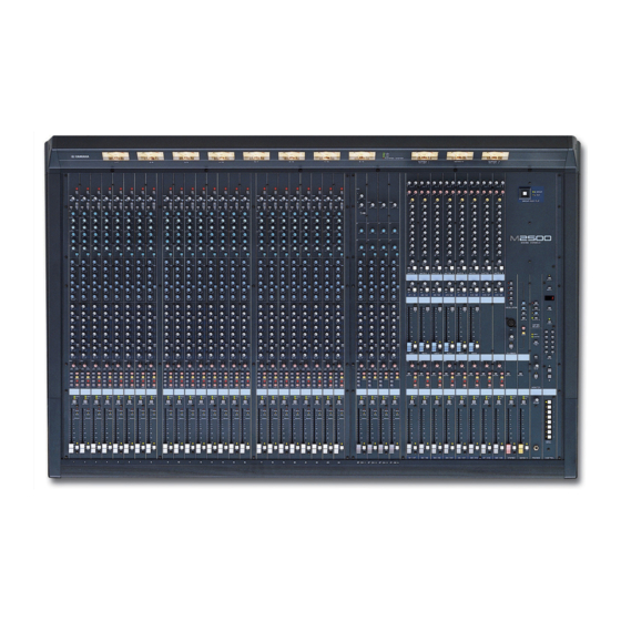
Introduction Thank you for purchasing the Yamaha M2500 mixing console. The M2500 is a highly cost- effective mixing console that features functionality such as scene memory, PAN control that is switchable between LR/LCR, and GROUP/AUX FADER FLIP switches. In order to take full advantage of the M2500’s functionality and ensure trouble-free use, please read... -
Page 6: Features Of The System
Scenes can be recalled at any time from the front of 25 output buses. The M2500 is ideal for a panel or via MIDI. In addition, control change wide range of applications from use as a main messages can be used to individually switch PA mixer to use in installed systems. -
Page 7: Control Panel
), phantom power is on. At this time Monaural input channels the indicator above the switch will light. The M2500-24 {32/40C/48C/56C} provides 24 {32/ Note: If you wish to use phantom power, make 40/48/56} input channels. The specifications of each... -
Page 8: Pan Control
STEREO bus and the els sent to GROUP buses 1–8 as shown in the MONO/C bus. following diagram. < Response curve 3 > 1-2/3-4/5-6/7-8 switches= on Signal sent to GROUP buses 1/3/5/7 Signal sent to GROUP buses 2/4/6/8 EVEN PAN control M2500—Owner’s Manual... -
Page 9: Channel Fader
M PEAK/NOM/SIGNAL indicators The function of this switch and these indicators will These three indicators allow you to check the pre- change depending on the mode of the M2500. fader signal level of the monaural input channel. • PEAK indicator... - Page 10 Control panel Stereo input channels The M2500 provides four stereo input channels, allowing line-level stereo sources such as sub-mixers, effect processors, and CD players to be input. Of the stereo input channels 1–4, channel 1 provides both XLR and RCA phono input jacks, and you can select GAIN and use one of these.
- Page 11 The function of this switch and these indicators will pressed in ( ), the equalizer is on. change depending on the mode of the M2500. F AUX 1–AUX 14 controls In normal mode These adjust the level at which the signal of the stereo...
- Page 12 ON/EDIT AUX3 from CPU AUX4 AUX5 AUX6 AUX 7-10 Same as AUX 3-6 AUX 11-14 Same as AUX 3-6 L/MONO 2 stage EQ ST CH 2-4 ST CH 2-4 Same as ST CH 1 INPUT 2 stage EQ M2500—Owner’s Manual...
-
Page 13: Group/Aux Master Section
MONITOR MASTER PFL/AFL buses and can be monitored from the MONITOR OUT L/R and the PHONES jacks. MONITOR INPUT MASTER (PFL) INSERT I/O AUX 1 to METER AUX OUT +4dB AUX 2-6 Same as AUX 1 M2500—Owner’s Manual... -
Page 14: Level Control
GROUP/AUX FLIP switch= AUX ( The signals of GROUP buses 1–8 will be sent to chan- nels A7/G1–A14/G8 respectively, and output individ- ually from the AUX/GRP OUT A7/G1–A14/G8 jacks. LEVEL LEVEL A7 / G1 A8 / G2 EVEN MONO M2500—Owner’s Manual... - Page 15 The signals of GROUP buses 1–8 will be sent to chan- MONO MONO nels G1/A7–G8/A14 respectively, and will be output individually from the GRP/AUX OUT G1/A7–G8/ A14 jacks. CHECK CHECK ON/EDIT ON/EDIT EVEN G1 / A7 G2 / A8 MONO M2500—Owner’s Manual...
- Page 16 G1/A7–G8/A14 section will be sent to the ST bus. If the MONO switch is on, the signal of the G1/A7–G8/A14 section will be sent directly to the MONO/C bus. (Refer to response curve diagram 2 on page 4.) M2500—Owner’s Manual...
- Page 17 G Fader The function of this switch and these indicators will This adjusts the output level of the GRP/AUX OUT. change depending on the mode of the M2500. H AFL (after fader listen) switch In normal mode This switch allows you to monitor the signal of the You can use the ON/EDIT switch to turn each G1/ G1/A7–G8/A14 section from the MONITOR OUT/...
-
Page 18: Group/Aux Flip Switch
STEREO bus GROUP buses 1–8 can be used as group buses. This set- MONO/C bus ting is more convenient when you are using the M2500 MATRIX bus as a main console, since you will be able to use the 100 mm faders to control the group buses. - Page 19 AUX buses 7–14 Master control Rotary faders 100 mm faders 100 mm faders Channel assign switch (MATRIX/ST/MONO/LCR) PAN control Mute switch ON/EDIT INSERT I/O Note: The output channels of AUX buses 1–6 are not affected by the GROUP/AUX FLIP switch. M2500—Owner’s Manual...
-
Page 20: Stereo/Monaural Master Section
F ON/EDIT switch / ON, CHECK indicators The function of this switch and these indicators will STEREO MONO/C change depending on the mode of the M2500. In normal mode You can use the ON/EDIT switch to turn MONO/C STEREO section OUT on/off. - Page 21 INSERT I/O ST L ST OUT +4dB CHECK Control ON/EDIT from CPU MATRIX INSERT I/O ST R ST OUT +4dB INSERT I/O MONO/C +4dB MONO/C CHECK MATRIX Control ON/EDIT from CPU MONITOR LEVEL +4dB MASTER MONO/C INPUT MASTER PHONES M2500—Owner’s Manual...
-
Page 22: Matrix Section
(page 11) are on, these controls adjust the level of the signal that is sent from the corresponding The M2500 provides an eight channel matrix section GRP/AUX OUT to the matrix. The “ ” position is that allows the output signals from the G1/A7–G8/ nominal level. -
Page 23: Monitor Section
The PHONES jack will monitor the ST OUT (L/R) jacks. If this switch is off ( ), the MONITOR MAS- output signal. TER AFL signals (after-fader signals of priority order 2) can be monitored from the MONITOR OUT/ PHONES jacks. M2500—Owner’s Manual... -
Page 24: Phones Jack
INSERT I/O ST L ST OUT +4dB CHECK Control ON/EDIT from CPU MATRIX INSERT I/O ST R ST OUT +4dB INSERT I/O MONO/C +4dB MONO/C CHECK MATRIX Control ON/EDIT from CPU MONITOR LEVEL +4dB MASTER MONO/C INPUT MASTER PHONES M2500—Owner’s Manual... -
Page 25: Talkback/Oscillator Section
This adjusts the level of the talkback or oscillator. E ON switch This is an on/off switch for the talkback. If this is on, the indicator above the switch will light. If you wish to use the oscillator, you must turn off this switch. M2500—Owner’s Manual... -
Page 26: Meter Select Section
Meter select section Control section In this section you can select the source whose level The M2500 is able to save “scenes“ that contain the will be displayed by the meter bridge section. Only on/off status for each monaural/stereo input channel, one of the sources 1–4 can be selected. -
Page 27: Utility Switch
“ ,” indicating that the M2500 is ready to store the scene. If you press the Note: Be aware that in Check mode, pressing a STORE switch once again, the scene will be stored. If... -
Page 28: Meter Bridge
The MONO/C level meter will not function. panel DC POWER INPUT connector (page 29) to This meter has a PEAK indicator that lights 3 dB the M2500 mixer. before peak level. C PHANTOM MASTER indicator This will light when the rear panel PHANTOM MAS- TER switch (page 29) is on. -
Page 29: Rear Panel
0 dB. The pin wiring is as follows. Tip (send) 1/4" phone plug Tip (send) Ring (return) To processor’s input Sleeve (ground) 1/4" TRS phone plug Tip (return) Sleeve (ground) 1/4" phone plug Connect to INSERT I/O jack From processor’s output Sleeve (ground) M2500—Owner’s Manual... -
Page 30: Stereo Input Channel Input/Output Jacks
–20 dB. In order to use these jacks, you must set the A/B select switch of stereo input channel 1 to the B position. The pin wiring is as follows. RCA phono plug Tip (send) Sleeve (ground) M2500—Owner’s Manual... -
Page 31: Master Section Input/Output Jacks
+4 dB. The pin wiring is as follows. G1/A7–G8/A14 section. Nominal output level is +4 dB. The pin wiring is as follows. 2 (hot) Female XLR plug 3 (cold) 2 (hot) Female XLR plug 3 (cold) 1 (ground) 1 (ground) M2500—Owner’s Manual... - Page 32 These are 1/4" phone jacks (unbalanced) for mixing a line level signal from an external device into the STE- REO bus L/R and MONO/C bus respectively. Nomi- nal input level is +4 dB. The pin wiring is as follows. Tip (send) 1/4" phone plug Sleeve (ground) M2500—Owner’s Manual...
-
Page 33: Lamp Connector
In this case, each PW3000MA connecting these to a sequencer or to the MIDI inter- will supply 50% of the power to the M2500. In the face of a computer, scenes can be selected from an unlikely event that one of the PW3000MA units fail, external device, or scene memories can be backed up. -
Page 34: The Scene Memory Function
This is the normal operating mode in which scenes connector can also recall scenes, and when a scene is are recalled and stored. When the M2500 is in Nor- recalled, a corresponding program change message mal mode, the indicators of the CHECK switch and can be transmitted from the MIDI OUT connector. -
Page 35: Operation In Normal Mode
0–9/ENTER switches. Storing a scene 2. Press the RECALL switch. 1. With the M2500 in Normal mode, use the ON/ EDIT switches of the monaural/stereo input RECALL channels, the G1/A7–G8/A14 section, the STE- REO section, and the MONO/C section to make The scene of the selected scene memory number will the desired on/off settings. -
Page 36: Check Mode Operation
MONO/C section. This allows you to check the on/ stored. (With the factory settings, this is turned off settings of the selected scene before you actually off.) To turn memory protect off, refer to page 34. recall it. M2500—Owner’s Manual... - Page 37 The scene whose on/off settings you checked will be 3. Use the ON/EDIT switches of each monaural/ recalled, and the M2500 will automatically return to Nor- stereo input channel, the G1/A7–G8/A14 sec- mal mode. If you wish to return to Normal mode without tion, the STEREO section, and the MONO/C recalling the scene, press the CHECK switch once again.
-
Page 38: Utility Mode Procedures
Note: If a MIDI program change is received while • If “ ” is selected in Utility mode, the M2500 will return to Normal All scene memories (1–128) will be erased. mode. • If “ ”–“ ” is selected The scene memory of the corresponding number (1–... - Page 39 Control change messages will not be transmitted or via its MIDI IN/OUT connectors, the scene memory received. contents of the other M2500 will be copied to the first M2500. Specify the value and press the STORE key to • If “...
-
Page 40: Control Change Table
“on.” Also, when you press an The following table shows the M2500 channels (and ON/EDIT switch on the M2500 to turn it on/off, the mute groups) that correspond to each control change corresponding control change number will be trans- number. -
Page 41: Mute Groups
Switch to the on/off settings of memory number 3 CHECK CHECK CHECK CHECK CHECK The mute settings of memory number 1 are cancelled ON/EDIT ON/EDIT ON/EDIT ON/EDIT ON/EDIT CHECK CHECK CHECK CHECK CHECK ON/EDIT ON/EDIT ON/EDIT ON/EDIT ON/EDIT MUTE MUTE M2500—Owner’s Manual... -
Page 42: About The Local Control Circuit
(off) settings of the channels that you wish to use as a mute group. In the unlikely event that the system of the M2500 2. Press the UTILITY switch to move to Utility experiences a malfunction so that the scene memory... -
Page 43: Error Messages
Error messages While the M2500 is being operated or when the power is turned on, the MEMORY display may show one of the following error messages. If this occurs, refer to the corresponding explanation and take appropriate action. An error occurred while receiving MIDI The voltage of the internal battery has data. -
Page 44: Specifications
20 kHz filter with infinite dB/octave attenuation. +15, –15 dB maximum HIGH 10 kHz (shelving) For European Model HIGH-MID 400– 8 kHz (peaking) Purchaser/User information specified in EN55103-1 and EN55103-2. LOW-MID 80–1.6 kHz (peaking) Conformed Enviroment: E1, E2, E3 and E4. 100 Hz (shelving) M2500—Owner’s Manual... -
Page 45: Input/Output Characteristics
20 mW 100 Ω PHONES OUT [L, R] Stereo Phone Jack 40 Ω Phones 30 mW 75 mW *1 0 dB=0.775 Vrms. *2 Balanced. *3 Unbalanced (T=OUTPUT, R=INPUT, S=GND). *4 Unbalanced. *5 n=56, 48, 40, 32 or 24 M2500—Owner’s Manual... -
Page 46: Other
Power supply remote +15 V ±15 V GND +48 V GND –15 V +12 V +12 V GND / power supply remote Power supply remote +48 V FRAME GND Included items Power supply connection cable (3 m, 10 pin) M2500—Owner’s Manual... -
Page 47: Dimensions
Dimensions Front Side 1400: M2500-24 1642: M2500-32 1899: M2500-40C 2142: M2500-48C 2385: M2500-56C Rear M2500-24 M2500-32 M2500-40C M2500-48C M2500-56C Units: mm M2500—Owner’s Manual... -
Page 48: Midi Data Format
2. MIDI Program Change STATUS 11110000 F0h System Exclusive Message Program change numbers (0–127) correspond to ID No. 01000011 43h Manufacturer's ID No.(YAMAHA) SUB STATUS 0000xxxx 0nh n=0~15(MIDI Channel) scene memory numbers 1–128. This correspondence FORMAT No. 01111110 7Eh Universal Bulk Dump cannot be changed. -
Page 49: Midi Implementation Chart
MIDI Implementation Chart MIDI Implementation Chart Function... Transmitted Recognized Remarks M2500—Owner’s Manual... - Page 50 YAMAHA CORPORATION V443030 R0 1 IP 148 Pro Audio Division, #18/3 P.O. Box 3, Hamamatsu, 430-8651, Japan NP Printed in Taiwan...
Need help?
Do you have a question about the M2500 and is the answer not in the manual?
Questions and answers