Mitsubishi Electric XL2550U User Manual
Hide thumbs
Also See for XL2550U:
- User manual (47 pages) ,
- Network manual (17 pages) ,
- Control manual (9 pages)
Table of Contents
Advertisement
Quick Links
Download this manual
See also:
Network Manual
Advertisement
Table of Contents

Related Manuals for Mitsubishi Electric XL2550U


Summary of Contents for Mitsubishi Electric XL2550U
- Page 1 LCD PROJECTOR MODEL XL2550U XL1550U User Manual XL2550 XL1550 This User Manual is important to you. Please read it before using your projector.
- Page 2 CAUTION RISK OF ELECTRIC SHOCK DO NOT OPEN CAUTION : TO REDUCE THE RISK OF ELECTRIC SHOCK, DO NOT REMOVE COVER (OR BACK) NO USER-SERVICEABLE PARTS INSIDE REFER SERVICING TO QUALIFIED SERVICE PERSONNEL. The lightning fl ash with arrowhead symbol within an equilateral triangle is intended to alert the user to the presence of uninsulated “dangerous voltage”...
-
Page 3: Table Of Contents
This symbol mark is according to the directive 2002/96/EC Article 10 Information for users and Annex IV. Your MITSUBISHI ELECTRIC product is designed and manufactured with high quality materials and components which can be recycled and reused. This symbol means that electrical and electronic equipment, at their end-of-life, should be disposed of separately from your household waste. -
Page 4: Important Safeguards
Important safeguards Please read all these instructions regarding your 10. Power sources projector and retain them for future reference. Follow This projector should be operated only from the all warnings and instructions marked on the projector. type of power source indicated on the marking label. - Page 5 Important safeguards (continued) WARNING: of the air outlet grille. The air outlet grille and bottom plate, when heated, may cause injury or damage to Unplug immediately if there is something other equipment. Also, do not set the projector on the wrong with your projector.
-
Page 6: Preparing Your Projector
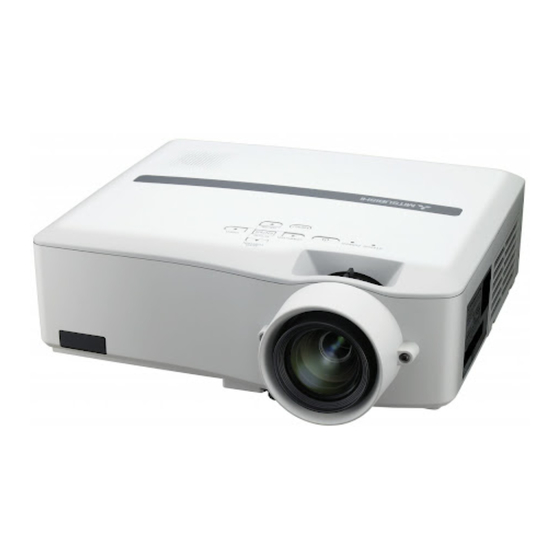
Preparing your projector Checking accessories The following accessories are provided with this projector. Check to be sure that all of the accessories are packed in the package. Cables Mini D-SUB D-SUB 15-pin USB 4 -pin 9-pin (type B) Mini D-SUB D-SUB 15-pin USB 4 -pin... - Page 7 Preparating your projector (continued) Overview 1 Speaker 2 Air inlet grille/Filter cover 3 Control area 4 ZOOM ring 5 FOCUS ring 6 Remote control sensor (Front) 7 Air outlet grille 8 Lamp cover 9 Air outlet grille 10 Remote control sensor (Rear) 11 Kensington Security Lock Standard connector 12 Lock bar (SECURITY ANCHOR) •...
- Page 8 Preparating your projector (continued) Bottom side 1 Adjustment foot (for vertical position) 2 Adjustment foot (for horizontal position) Remote control 1 Laser aperture 2 Transmission window 3 Indicator 4 POWER button 5 VIDEO button 6 DVI-D (HDCP) button 7 HOME button 8 END button 9 Mouse pointer 10 MENU button...
-
Page 9: Using The Remote Control
Using the remote control Operational range of the remote control • Keep the remote control photo-sensor out of direct sunlight or fl uorescent lamp light. • Keep the remote control photo-sensor at least 2 m (6 feet) away from fl uorescent lamps. Otherwise, the Rear of projector Front of projector remote control may malfunction. -
Page 10: Setting Up Your Projector
Setting up your projector Setting up the screen Install the screen perpendicularly to the projector. If the screen can not be installed in such a way, adjust the projection angle of the projector. (See below.) • Install the screen and projector so that the projector’s lens is placed at the same height and horizontal position of the screen center. - Page 11 Setting up your projector (continued) Front projection, ceiling mounting Caution: For ceiling mounting, you need the ceiling mount kit • Placing the projector directly on a carpet impairs designed for this projector. Ask a specialist for installa- ventilation by the fans, causing damage or failure. tion.
-
Page 12: Screen Size And Projection Distance
Setting up your projector (continued) Screen size and projection distance Refer to the following table to determine the screen size. Screen size Center of the lens Projection distance (L) (Width of the projected image) When the aspect ratio of the screen is 4:3 Screen size Projection distance (L) 4:3 Diagonal size... -
Page 13: Viewing Computer Images
Viewing computer images A. Connecting the projector to a computer Preparation: • Make sure that the power of the projector and that of the computer are turned off. • When connecting the projector to a desktop computer, disconnect the RGB cable that is connected to the monitor. Computer For analog connection: COMPUTER/COMPONENT... - Page 14 Viewing computer images (continued) About DDC The COMPUTER/COMPONENT VIDEO IN-1 terminal of this projector complies with the DDC1/2B standard and the COMPUTER/COMPONENT VIDEO DVI-D (HDCP) terminal complies with the DDC2B standard. When a computer supporting this standard is connected to this terminal, the computer will automatically load the information from this projector and prepare for output of appropriate images.
- Page 15 Viewing computer images (continued) C. Projecting images Preparation: • Remove the lens cap. • Turn on the power of the connected computer. COMPUTER 1, 2 buttons POWER button DVI-D(HDCP) button FOCUS ring ZOOM ring COMPUTER button POWER button 1. Confi rm the POWER indicator lights up red. •...
- Page 16 Viewing computer images (continued) POWER button POWER button To stop projecting: 8. Press the POWER button. • A confi rmation message is displayed. • To cancel the procedure, leave the projector for a while or press the MENU button. 9. Press the POWER button. •...
-
Page 17: Viewing Video Images
Viewing video images A. Connecting the projector to video equipment Preparation: • Make sure that the power of the projector and that of the video equipment are turned off. Connecting to a video player, etc. Video player, or the like 1. - Page 18 Viewing video images (continued) Projector + DVD player or HDTV decoder Some DVD players have an output connector for 3-line fi tting (Y, C ). When connecting such DVD player with this projector, use the COMPUTER/COMPONENT VIDEO IN-1/IN-2 terminal. Mini D-SUB 15 pin-BNC Conversion cable (option) HD/CS COMPUTER/COMPONENT VIDEO...
- Page 19 Viewing video images (continued) C. Projecting images Preparation: • Remove the lens cap. • Turn on the power of the connected video equipment. POWER button COMPUTER1, 2 buttons FOCUS ring DVI-D (HDCP) button S-VIDEO button VIDEO button ZOOM ring COMPUTER button POWER button VIDEO button 1.
- Page 20 Viewing video images (continued) POWER button POWER button To stop projecting: 8. Press the POWER button. • A confi rmation message is displayed. • To cancel the procedure, leave the projector for a while or press the MENU button. 9. Press the POWER button. •...
- Page 21 Viewing video images (continued) Setting the aspect ratio You can change the aspect ratio of the input video signal (or the ratio of width to height of the image). Change the setting according to the type of the input video signal. How to change the settings: With the remote control: 1.
-
Page 22: Menu Operation
Menu operation • Menus are not displayed when no signal is supplied to the projector. IMAGE COLOR ENHANCER AUTO PRESENTATION STANDARD THEATER GAMMA MODE DYNAMIC, NATURAL, DETAIL sRGB RGB-COLOR ±10 USER RGB-TINT ±10 CONTRAST ±30 CONTRAST R ±30 BRIGHTNESS ±30 CONTRAST G ±30 COLOR TEMP. -
Page 23: How To Set The Menus
Menu operation (continued) 4. Press the S or T button to select an item to adjust. How to set the menus: Following describe how to set AUTO POWER OFF AUTO POWER time. AUTO POWER 1. Press the MENU button. 5. Set the selected item by pressing the W or X button. opt. - Page 24 Menu operation (continued) 2. INSTALLATION menu opt. INSTALLATION WALL SCREEN BEIGE LAMP MODE STANDARD AUTO POWER AUTO POWER IMAGE SETUP CAPTURE SPLASH SCREEN BACK COLOR BLUE MUTE MODE BLACK IMAGE REVERSE ITEM SETTING FUNCTION WALL SCREEN OFF / BEIGE Select any option depending on the color of the wall on which images are LIGHT BLUE projected.
- Page 25 Menu operation (continued) 3. FEATURE menu opt. FEATURE ASPECT AUTO PASSWORD DISPLAY FUNCTION INPUT MENU POSITION AUTO CINEMA MODE VIDEO SIGNAL AUTO SETUP AUTO SCART INPUT LANGUAGE English Ë RESET ALL ITEM SETTING FUNCTION ASPECT AUTO Select to change the aspect ratio automatically depending on the input signal.
- Page 26 Menu operation (continued) 4. SIGNAL menu SIGNAL - RESOLUTION (MEMORIZE) menu SIGNAL - USER menu opt. opt. opt. SIGNAL SIGNAL SIGNAL RESOLUTION (MEMORIZE) USER MEMORY CALL AUTO RESOLUTION VERTICAL CLAMP 1024x768 75.04 Hz (MEMORIZE POSITION FREQUENCY HORIZONTAL HORIZ. POSITION 60.02 KHz CLAMP WIDTH FREQUENCY HORIZ.
- Page 27 Menu operation (continued) 5. INFORMATION menu opt. INFORMATION LAMP TIME (LOW) INPUT COMPUTER2 RESOLUTION 1024x768 VERTICAL 75.04 Hz FREQUENCY HORIZONTAL 60.02 KHz FREQUENCY SYNC. TYPE 5wire ITEM DESCRIPTION LAMP TIME (LOW) This item shows a lamp operating time (hour) calculated based on that LAMP MODE is LOW. •...
-
Page 28: Adjusting Projected Images
Adjusting projected images To adjust the brightness (CONTRAST and BRIGHTNESS): You can make adjustments for the brightness of the projected image using the menu. (See page 23 for menu setting.) 1. Display the IMAGE menu. 2. Select CONTRAST or BRIGHTNESS by pressing the S or T button. 3. - Page 29 Adjusting projected images (continued) To adjust the tone of white (COLOR TEMP.): You can select a preset color temperature (white tone) using the menu. (See page 23 for menu setting.) 1. Display the IMAGE menu. 2. Select COLOR TEMP. by pressing the S or T button. 3.
- Page 30 Adjusting projected images (continued) This projector automatically selects a proper signal format according to the type of video signal supplied from the computer. However, video signals from the computer may not be projected correctly depending on the types of the computer and images to be projected.
- Page 31 Adjusting projected images (continued) How to adjust the image supplied from the computer using the menu: Carry out the following procedures according to the symptoms. Wide strips appear. ……………………………………… Adjust TRACKING in the SIGNAL menu. The projected image fl ickers. The projected image is blurred.
-
Page 32: Advanced Features
Advanced features Setting of the image displayed during startup or muting You can display your desired image as the startup CAPTURE : ENTER X2 screen (or splash screen). Using the menu, you can CANCEL : MENU CAPTURE : ENTER + ENTER CANCEL : MENU also use such image as a background that is displayed while the video is muted or no signal is supplied. - Page 33 Advanced features (continued) Password function 9. Press the ENTER button. • If the entered passwords don’t match, an error This projector is equipped with the password function message will appear. that is designed for prevention of wrong operation by • To cancel the procedure, press the MENU children and restriction on operation by other than button.
- Page 34 Advanced features (continued) Expand • When the COMPUTER 1, COMPUTER 2 or DVI-D (HDCP) button on the remote control or the By pressing the EXPAND button on the remote control, COMPUTER button on the control panel is pressed, you can magnify the image to view the details. the PinP mode will be canceled.
- Page 35 Advanced features (continued) Mouse remote control By connecting to personal computer through the USB port, you can operate your computer with the projector remote control. Projector + computer with USB connector To USB port USB cable USB 4-pin USB 4-pin (type A) (type B) •...
-
Page 36: Supervising And Controlling By Computer
Advanced features (continued) Supervising and controlling by computer You can supervise and control the projector’s operation using a personal computer via a LAN network. • To supervise and control the projector, install the software “Projector-Control Device Installer *” contained in the attached CD-ROM. -
Page 37: Indicators
Indicators This projector has 2 indicators, each of which shows the operation condition of the projector. The following offer solutions to possible problems. If these problems persist, turn the projector off and consult your dealer. POWER indicator STATUS indicator Normal condition NOTE POWER S TA TUS... -
Page 38: Replacing The Lamp
• When removing the lamp from the ceiling-mounted projector, use the lamp replacement tray packed with the projector or option lamp to prevent glass fragments from scattering. • Be sure to use the lamp exclusive to this projector, VLT-XL650LP for XL2550U (or VLT-XL550LP for XL1550U). Use of other lamps may cause a failure of the projector. -
Page 39: Removing Lamp From Ceiling-Mounted Projector
Replacing the lamp (continued) To replace the lamp: 1. Unplug the power cord. 2. Loosen the screw (a) using a Phillips screwdriver (+), and remove the lamp cover (b). 3. Loosen the screws (c) using a Phillips screwdriver (+). 4. Pull the handle. 5. -
Page 40: Maintenance
Maintenance Warning: • Never use fl ammable air duster or other materials when cleaning the air-fi lter. Flammable substances may ignite causing fi re or backdown when the lamp is illuminated. • Do not use fl ammable solvents (benzene, thinner, etc.) and fl ammable aerosols when cleaning the projector body and lens. -
Page 41: Troubleshooting
Troubleshooting Before asking for repair of the projector, check the following. If the symptom persists, stop using the projector, be sure to unplug the power plug, and then contact your dealer. No image appears on the screen. Problem Solution Power can not be •... - Page 42 Troubleshooting (continued) No image appears on the screen. (continued) Problem Solution The screen for entering • PASSWORD FUNCTION in the FEATURE menu has been set to DISPLAY INPUT the password appears. enable the password lock. J Enter the password or contact the person in charge of management of the projector.
- Page 43 Troubleshooting (continued) Images are not displayed correctly. (continued) Problem Solution Only the motion areas • This is caused by the computer being used. Contact the manufacturer of your in the images supplied computer. from the computer aren’t displayed. Projected images are •...
-
Page 44: Specifi Cations
Active pixel rate: 99.99% or more (each panel) Projection lens F 1.7 - 2.0 f= 29 - 37 mm Light-source lamp 261 W (XL2550U) / 200 W (XL1550U) Image size (Projection distance) 40” min. to 300” max. (Projection distance 1.4 to 10.9 m) Maximum... - Page 45 Specifi cation of RGB signals in each computer mode of the projector Signal mode resolution horizontal Vertical Normal mode Real mode (H x V) frequency (kHz) frequency (Hz) (H x V) (H x V) TV60, 480i(525i) 15.73 59.94 1024 x 768 TV50, 576i(625i) 15.63 50.00...
- Page 46 Specifi cations (continued) DVI-D (HDCP) COMPUTER/COMPONENT VIDEO IN-1/IN-2 Connectors (DVI-D 24-pin) (Mini D-SUB 15-pin) SERIAL (D-SUB 9-pin) Pin No. Spec. R(RED)/P G(GREEN)/Y PIN No. Spec. PIN No. Spec. B(BLUE)/P TMDS DATA 2- TMDS DATA 2+ +5V Power Pin No. Name TMDS DATA 2 Shield Ground (for +5V) Hot Plug Detect...
- Page 47 Technical Inquiries :+886-2-2833-9813 Centro Direzionale Colleoni, Palazzo Sirio, Viale Colleoni 7, Phone :+852-2422-0161 20041 Agrate Brianza, Italy MKY (Mitsubishi Electric Kang Yong Watana Co., Ltd. ) :+852-2487-0181 Sales & Technical Inquiries http://www.mitsubishi-kyw.co.th/ SINGAPORE (Mitsubishi Electric Asia Pte. Ltd.) Phone :+39-(0)39-60531 Road, Huamark Bangkapi, Bangkok 10240, Thailand http://www.mitsubishielectric.com.sg...
Need help?
Do you have a question about the XL2550U and is the answer not in the manual?
Questions and answers