Yamaha RX-V461 Service Manual
Av receiver
Hide thumbs
Also See for RX-V461:
- Owner's manual (322 pages) ,
- Service manual (94 pages) ,
- Service manual (57 pages)
Table of Contents
Advertisement
This service manual is the RX-V461/HTR-6040/RX-V461DAB (T, B, G and E models).
For the RX-V461/HTR-6040/DSP-AX461 (U, C, R, K, A, L and J models) service manual, please refer to the
following service manual:
RX-V461/HTR-6040/DSP-AX461 (U, C, R, K, A, L and J models): 101041
This manual has been provided for the use of authorized YAMAHA Retailers and their service personnel.
It has been assumed that basic service procedures inherent to the industry, and more specifically YAMAHA Products, are already
known and understood by the users, and have therefore not been restated.
WARNING:
IMPORTANT:
The data provided is believed to be accurate and applicable to the unit(s) indicated on the cover. The research, engineering, and
service departments of YAMAHA are continually striving to improve YAMAHA products. Modifications are, therefore, inevitable
and specifications are subject to change without notice or obligation to retrofit. Should any discrepancy appear to exist, please
contact the distributor's Service Division.
WARNING:
IMPORTANT:
I CONTENTS
To Service Personnel .......................................... 2
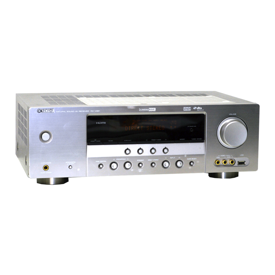
Front Panels ............................................................ 3
Rear Panels .......................................................... 4–5
Remote Control Panels ...................................... 6
Specifications ...................................................... 7–9
Internal View ......................................................... 10
Disassembly Procedures ........................... 10–12
Updating Firmware ........................................ 13–14
Self Diagnosis Function (Diag) ................. 15–29
1 0 1 0 4 8
RX-V461/HTR-6040/
RX-V461DAB
For T, B, G and E models
IMPORTANT NOTICE
Failure to follow appropriate service and safety procedures when servicing this product may result in personal
injury, destruction of expensive components, and failure of the product to perform as specified. For these reasons,
we advise all YAMAHA product owners that any service required should be performed by an authorized
YAMAHA Retailer or the appointed service representative.
The presentation or sale of this manual to any individual or firm does not constitute authorization, certification or
recognition of any applicable technical capabilities, or establish a principle-agent relationship of any form.
Static discharges can destroy expensive components. Discharge any static electricity your body may have
accumulated by grounding yourself to the ground buss in the unit (heavy gauge black wires connect to this buss).
Turn the unit OFF during disassembly and part replacement. Recheck all work before you apply power to the unit.
Display Data ..................................................... 30–31
Ic Data ................................................................. 32–47
Block Diagrams .............................................. 49–50
Pin Connection Diagrams .................................. 51
Printed Circuit Boards ................................ 52–66
Schematic Diagrams ...................................... 67–80
Replacement Parts List .............................. 81–91
Remote Control .............................................. 92–93
Advanced Setup ........................................................... 94
2007
This manual is copyrighted by YAMAHA and may not be copied or
redistributed either in print or electronically without permission.
AV RECEIVER
SERVICE MANUAL
All rights reserved.
P.O.Box 1, Hamamatsu, Japan
'07.07
Advertisement
Table of Contents

Related Manuals for Yamaha RX-V461


Summary of Contents for Yamaha RX-V461
-
Page 1: Service Manual
For T, B, G and E models This service manual is the RX-V461/HTR-6040/RX-V461DAB (T, B, G and E models). For the RX-V461/HTR-6040/DSP-AX461 (U, C, R, K, A, L and J models) service manual, please refer to the following service manual:... -
Page 2: To Service Personnel
RX-V461/HTR-6040/RX-V461DAB I TO SERVICE PERSONNEL 1. Critical Components Information AC LEAKAGE WALL EQUIPMENT TESTER OR Components having special characteristics are marked s and OUTLET UNDER TEST EQUIVALENT must be replaced with parts having specifications equal to those originally installed. 2. Leakage Current Measurement (For 120V Models Only) -
Page 7: Specifications
Band III ................-99 dBm ....fc=40/60/80/90/100/110/120/160/200 Hz, 24 dB/oct. L-Band ................. -95 dBm “SILENT CINEMA” is a trademark of YAMAHA CORPORATION. Multimedia (USB) Applications Selectivity (For adjacent channel) T, G, E models ..Connections USB mass storage class device Band III / L-Band .............. - Page 8 RX-V461/HTR-6040/RX-V461DAB • SCENE TEMPLATE Program Select (Default) SCENE name Contents Source Mode Sub-mode T model B model G, E models DVD Viewing Movie STRAIGHT – DVD Movie Viewing MOVIE THEATER Movie Dramatic O (SCENE 1) O (SCENE 1) O (SCENE 1)
- Page 9 RX-V461/HTR-6040/RX-V461DAB...
-
Page 10: Internal View
RX-V461/HTR-6040/RX-V461DAB I INTERNAL VIEW I DISASSEMBLY PROCEDURES (Remove parts in the order as numbered.) • Top view Disconnect the power cable from the AC outlet. B model 1. Removal of Top Cover 2. Removal of Front Panel Unit a. Remove 4 screws (1), 4 screws (2) and 1 screw (3). - Page 11 RX-V461/HTR-6040/RX-V461DAB Rear panel B model DAB P.C.B. CB361 T, G, E models CB362 HDMI P.C.B. CB905 CB906 CB301 (B model) CB305 VIDEO (1) P.C.B. DSP P.C.B. DSP P.C.B. CB502 CB512 CB501 Rear panel CB516 CB193 Cord stopper CB322 CB101 CB104 MAIN (1) P.C.B.
- Page 12 RX-V461/HTR-6040/RX-V461DAB When checking the P.C.B.: a. Remove the top cover. (Fig. 1) b. Remove 3 screws (9). (Fig. 3) c. Remove 5 screws (B) and 4 screws (C). (Fig. 4) d. Place the P.C.B. upright. (Fig. 5) e. The rear panel and P.C.B. removed from the chassis does not work because its grounding is loose.
-
Page 13: Updating Firmware
RX-V461/HTR-6040/RX-V461DAB I UPDATING FIRMWARE After replacing the following parts with the replacement part, be sure to write the latest firmware. • DSP P.C.B. • IC201 (DSP P.C.B.) G Required Tools G Operation Procedures • DVD or CD player (with DIGITAL OUTPUT (OPTICAL 1. - Page 14 RX-V461/HTR-6040/RX-V461DAB 2. While pressing the “STANDBY/ON” key and “SPEAKERS A/B/OFF” key of the main unit simultaneously, connect the power cable of the main unit to the AC outlet. (Fig. 2) The FIRMWARE UPDATE mode will then be activated and “SPDIF Upgrade” is displayed. (Fig. 2)
- Page 15 RX-V461/HTR-6040/RX-V461DAB I SELF DIAGNOSIS FUNCTION (DIAG) This unit has self diagnosis functions that are intended for inspection, measurement and location of faulty point. DIAG menu Sub-menu There are 18 DIAG menu items, each of which has sub-menu items. IF STATUS IF 1 Listed in the table below are menu items and sub-menu items.
- Page 16 RX-V461/HTR-6040/RX-V461DAB • Starting DIAG When there is a history of protection function: Press the “STANDBY/ON” key while simultaneously pressing those two keys of the main unit as indicated in the figure When there is a history of protection function due to excess current below.
- Page 17 RX-V461/HTR-6040/RX-V461DAB When there is a history of protection function due to excessive heat sink temperature THM PRT:xxx AD value when the protection function is working Cause: The temperature of the heat sink is excessive. Supplementary information: The protection function worked due to the temperature limit being exceeded.
- Page 18 RX-V461/HTR-6040/RX-V461DAB • Details of DIAG menu 1. BYPASS Using the sub-menu, it is possible to select ANALOG BYPASS output or DSP BYPASS output. ANALOG BYPASS The analog input sound signal is output to FRONT L/R with EFFECT OFF. 1.ANLOG BYPASS...
- Page 19 RX-V461/HTR-6040/RX-V461DAB 3. SPEAKER SET The analog switch settings for each sub-menu are as shown in the table below. FRONT : SML 0dB SMALL LARGE LARGE SWFR CENTER : NONE LARGE NONE LARGE SWFR LFE/B : FRNT LARGE SMALL SMALL FRONT...
- Page 20 RX-V461/HTR-6040/RX-V461DAB 4. 6CH INPUT The input source [MULTI CHANNEL INPUT] is selected. It is possible to select the 6-ohm/8-ohm by using the sub-menu. 6 ch INPUT 6-ohm 4.6ch INPUT 6 Ω INPUT: MULTI CH INPUT SPEAKER OUT: 1 kHz, SUBWOOFER OUTPUT: 50 Hz...
- Page 21 RX-V461/HTR-6040/RX-V461DAB 6. FL/OSD CHECK Use this program to check the FL display section and video control section. When checking the video control section, prepare a monitor, S video cable and video pin cable and connect them. Using the sub-menu operation, selection items of the FL display section and video display section vary as shown below.
- Page 22 RX-V461/HTR-6040/RX-V461DAB 7. TEST TONE The noise generator with a built-in microprocessor outputs the noise through the channels specified by the submenu. The noise frequency for LFE (SUBWOOFER) is 35 to 80 Hz. Other than that, the noise frequency is 500 to 2 kHz.
- Page 23 RX-V461/HTR-6040/RX-V461DAB 9. A/D DATA CHECK This menu is used to display the A/D conversion value of the microprocessor which detects panel keys of the main unit and protection functions in using the sub-menu. When K0/K1 menu is selected, keys become non-operable due to detection of the values of all keys. However, it is possible to advance to the next sub-menu by turning the VOLUME of the main unit.
- Page 24 RX-V461/HTR-6040/RX-V461DAB 10. XM STATUS Not applied to these models. 1 kHz, -1 dB / 44.1 kHz 10.1k - 1dB/44 1 kHz, -61 dB / 44.1 kHz 10.1k -61dB/44 Mute / 44.1 kHz 10.MUTE XM tone / 44.1 kHz 10.XM TONE /44 ISO tone / 44.1 kHz...
- Page 25 RX-V461/HTR-6040/RX-V461DAB 11. DOCK (B model) This menu is used to test the DOCK connector without the iPod itself. After turning off the power, short between pins No. 14 (TX) and No. 18 (RX), between pins No. 1 (PWR) and No. 17 (ACCPOW) and between pins No.
- Page 26 RX-V461/HTR-6040/RX-V461DAB 13. DAB CHECK (B model) Using the DIAG menu, it is possible to select DAB SCAN, DLS, SIGNAL QUALITY. DAB SCAN/SCL The channel that can be received is searched. When reception is completed the SCL (Service Label) is displayed.
- Page 27 RX-V461/HTR-6040/RX-V461DAB 15. PROTECTION SETTING The A/D setting value of each protection is displayed. (Reference voltage: 3.3 V=255) PRD (Amplifier DC protection) Low 15.PRD L : The minimum preset value of PRD is displayed. PRD (Amplifier DC protection) High 15.PRD H : The maximum preset value of PRD is displayed.
- Page 28 RX-V461/HTR-6040/RX-V461DAB 16. PROTECTION HISTORY 17. SOFT SWITCH Four protection histories are displayed. Note) As this is a development menu, do not change the function setting. Changing the function setting may hinder the Example proper operation. History 1 16.PRI: 90 This menu is used to switch the function settings on P.C.B.
- Page 29 RX-V461/HTR-6040/RX-V461DAB 18. ROM VER/SUM The version and checksum are displayed. The signal is processed using EFFECT OFF. Version 18. VER. B112 Firmware version of microprocessor is displayed. All checksum 18.A.SUM:CE61 Checksum value of microprocessor is displayed. Program checksum 18.P.SUM:F584 Checksum value of application and standby code program is displayed.
-
Page 30: Display Data
RX-V461/HTR-6040/RX-V461DAB I DISPLAY DATA G V2001 : 17-BT-29GNK (OPERATION P.C.B.) PATTERN AREA G PIN CONNECTION Pin No. 68 67 Connection F2 NX Pin No. Connection Note : 1) F1, F2 ..Filament pin 2) NP ..No pin 3) NX ..No extend pin 4) 1G~17G .. - Page 31 RX-V461/HTR-6040/RX-V461DAB G ANODE CONNECTION 13G-1G – – – – – – – – – –...
- Page 32 RX-V461/HTR-6040/RX-V461DAB I IC DATA IC101: ADSP-BF531 CPU (DSP P.C.B.) Microprocessor with DSP JTAG test Event controller/ Watch dock timer Core timer and emulation Real time clock Voltage regulator UART port IrDA® Memory L1 order L1 data management memory memory unit...
- Page 33 RX-V461/HTR-6040/RX-V461DAB Pin No. Port Name Function Name Detail of Function DGND – Ground of external DGND – Ground of external DGND – Ground of external VROUT2 /VINTSW Voltage regulator drive for Q101 VROUT1 /VINTSW Voltage regulator drive for Q101 VDDEXT VDDEXT –...
- Page 34 RX-V461/HTR-6040/RX-V461DAB Pin No. Port Name Function Name Detail of Function TSCLK1 TSCLK1 Serial port 1, serial transmission clock DR1SEC DR1SEC Serial port 1, secondary reception data DR1PRI DR1PRI Serial port 1, primary reception data RFS1 RFS1 Serial port 1, frame synchronization reception...
- Page 35 RX-V461/HTR-6040/RX-V461DAB Pin No. Port Name Function Name Detail of Function ADDR19 SDRAM address bus 19 ADDR18 SDRAM address bus 18 ADDR17 SDRAM address bus 17 ADDR16 SDRAM address bus 16 ADDR15 SDRAM address bus 15 ADDR14 SDRAM address bus 14...
- Page 36 RX-V461/HTR-6040/RX-V461DAB • Microprocessor extended port IC204-IC207: SN74LV573APWR (DSP P.C.B.) Octal 3-state D-latches with 3-state outputs IC204 Pin No. Port Name Function Name Detail of Function /EXPE Extended port enable Data bus 00 Data bus 01 Data bus 02 Data bus 03...
- Page 37 RX-V461/HTR-6040/RX-V461DAB IC206 Pin No. Port Name Function Name Detail of Function /EXPE Extended port enable Data bus 00 Data bus 01 Data bus 02 Data bus 03 Data bus 04 Data bus 05 Data bus 06 Data bus 07 DGND...
- Page 38 RX-V461/HTR-6040/RX-V461DAB • Microprocessor ADC select port IC401: ADC084S021CIMM (DSP P.C.B.) 4-channel, 200 kSPS, 8-bit A/D converter 8-Bit SCLK SUCCESSIVE APPROXIMATION DOUT ADC084S021 SCLK CONTROL LOGIC DOUT Pin No. Port Name Function Name Detail of Function /SPISEL1 CS for microprocessor +3.3S...
- Page 39 RX-V461/HTR-6040/RX-V461DAB IC402 Pin No. Port Name Function Name Detail of Function iPAP DOCK (iPod) detect (ACCPOW) (B model) DEST2 Destination 2 * Analog value to IN4 (IC401) LINKACTIVE XM_MUTE DGND (Pull-down) DGND Ground of external DGND Ground of external ADSEL2...
- Page 40 RX-V461/HTR-6040/RX-V461DAB IC301: AK4588VQ (DSP P.C.B.) 2/8-channel audio CODEC with DIR PVSS PVDD X'tal Clock Oscillator 8 to 3 Recovery Clock MCKO1 Generator Input MCKO2 Selector LRCK2 DAIF Audio BICK2 Decoder SDTO2 DAUX2 AVDD AVSS DVDD Error & CCLK Q-subcode DVSS...
- Page 41 RX-V461/HTR-6040/RX-V461DAB Pin No. Function Name Detail of Function INT1 Interrupt 1 pin BOUT Block-start output pin for receiver input “H” during first 40 flames TVDD – Output buffer power supply pin, 2.7 V to 5.5 V DVDD – Digital power supply pin, 4.5 V to 5.5 V DVSS –...
- Page 42 RX-V461/HTR-6040/RX-V461DAB Pin No. Function Name Detail of Function ROUT3 DAC3 R ch analog output pin No connect pin – No internal bonding / This pin should be opened LOUT2 DAC2 L ch analog output pin No connect pin – No internal bonding / This pin should be opened...
- Page 43 RX-V461/HTR-6040/RX-V461DAB IC161: R2A15215FP (MAIN P.C.B.) 49 48 46 45 38 37 34 33 A VCC MUTE A VCC N.C. A VEE A VEE N.C. TREL 0/-6/-12/-18dB ADCL BASSL2 BASSL1 ADCR N.C. AGND Bass/Treble 0~-95dB, -14~+14dB -∞ (2dBstep) MAIN +42~0dB N.C.
- Page 44 RX-V461/HTR-6040/RX-V461DAB Pin No. Function Name Detail of Function N.C. No connected SBLC L/R/C/SW/SL/SR/SBL/SBR ch terminal to connect capacitor to reduce noise from changing the volume SBLOUT FL/FR/C/SW/SL/SR/SBL/SBR ch output terminal AGND Analog GND terminal SBROUT FL/FR/C/SW/SL/SR/SBL/SBR ch output terminal SBRC...
- Page 45 RX-V461/HTR-6040/RX-V461DAB Pin No. Function Name Detail of Function AGND Analog GND terminal N.C. No connected INR1 L/R ch input terminal (input selector) INL1 L/R ch input terminal (input selector) INR2 L/R ch input terminal (input selector) INL2 L/R ch input terminal (input selector)
- Page 46 RX-V461/HTR-6040/RX-V461DAB IC201: M66003-0131FP-R (OPERATION P.C.B.) 18 digit 5x7 segment VFD controller/driver Display code CGROM SEG00 (35-bit x 166) (8-bit x 60) Segment SEG25 Code output write SEG26 circuit CGROM SEG34 Serial dot data data (35-bit x 16) write receive Code/...
- Page 47 RX-V461/HTR-6040/RX-V461DAB Pin No. Port Name Function Name Detail of Function /RESET Reset Reset input When "L", M66003 is initialized /CEFL Chip select input When "L", communication with the MCU is possible When "H", any instruction from the MCU is neglected...
- Page 48 RX-V461/HTR-6040/RX-V461DAB MEMO MEMO...
- Page 49 RX-V461/HTR-6040/RX-V461DAB I BLOCK DIAGRAMS Video, Audio and Power Supply Sections • See page 67-72 → • See page 73, 74 → MAIN OPERATION SCHEMATIC DIAGRAM • See page 79 → SCHEMATIC DIAGRAM • See page 75, 76 → • See page 77, 78 →...
- Page 50 RX-V461/HTR-6040/RX-V461DAB Control Section CONTROL LIST Input select VIA, VIB, VIC /OSDSEL /VR1 SSEL1-3 • See page 73, 74 → OPERATION Control bus SPISEL3-6 SCHEMATIC DIAGRAM /RESET from OPERATION /CCBE USB reset /IC_AK /RESET A/D select ADSEL0-2 /IC_AK OPERATION (9) IC505 IC505 •...
- Page 51 RX-V461/HTR-6040/RX-V461DAB I PIN CONNECTION DIAGRAMS • ICs SN74CBTLV16210GR SN74LV157APWR SN74AHCT245PWR ADC084S021 CIMM ADSP-BF531 CPU AK4588VQ AZ4580MTR-E1 SN74LV4051APWR SN74LV573APWR STK433-130-E STK433-330-E TC74HC4052AF W9864G6EH-7 BR25L320F-W EEPROM CXB1442AR-T4 KIA7805API KIA79M05PI-U LM61CIZ KIA7812API KIA7912PI • Diodes 1SS133, 176 1SS355 RB160L-40 TE25 KDS160-RTK OUTPUT INPUT...
- Page 52 RX-V461/HTR-6040/RX-V461DAB I PRINTED CIRCUIT BOARDS Circuit No. B, G, E D402 R409 DSP P.C.B. (Side A) MAIN (1) (CB161) R421 R603 VIDEO (1) (CB305) R651, 652 X : NOT USED (W3601) OPERATION (2) O : USED/APPLICABLE B model (CB232) B model •...
- Page 53 RX-V461/HTR-6040/RX-V461DAB DSP P.C.B. (Side B) T, G, E models B model T, G, E models B model • Semiconductor Location Ref no. Location B, G, E models D407 D409 D602 T, G, E models T, G, E models...
- Page 54 RX-V461/HTR-6040/RX-V461DAB OPERATION (1) P.C.B. (Side A) MAIN (4) (CB191) (CB408) W2001 /MICDET SSEL3 SSEL2 SSEL1 OPERATION (2) REM1 (CB235) /BLK CKFD DTFD /CEFD ADKEY1 ADKEY0 +3.3S V_CN OPERATION (10) (CB274) JK201 V_CTRL OPTIMIZER MIC VOLUME PRESET/TUNING/CH A/B/C/D/E MEMORY FM/AM EDIT...
- Page 55 RX-V461/HTR-6040/RX-V461DAB OPERATION (1) P.C.B. (Side B) IC202 • Semiconductor Location Ref no. Location Ref no. Location D2002 Q2004 D2004 Q2005 D2006 Q2011 D2008 Q2012 D2009 Q2013 IC201 Q2014 IC202 Q2015 Q2001 Q2016 Q2002 Q2017 Q2003...
- Page 56 RX-V461/HTR-6040/RX-V461DAB OPERATION (2) P.C.B. (Side A) IC237 IC236 IC235 IC232 IC233 IC234 IC238 OPERATION (1) (CB203) (CB516) XMPWR /PDET /RESET W2154 +3.3 CB233 +5XM W2151 CB231 CB234 OPERATION (3) MAIN (1) HDMI POWER TRANSFORMER (CB251) (CB103) (CB905) (CB362) T, G, E models...
- Page 57 RX-V461/HTR-6040/RX-V461DAB OPERATION (2) P.C.B. (Side B) T, G, E models B model B model T, G, E models • Semiconductor Location Ref no. Location D2151 D2154 D2156 D2157 D2160 D2161 D2165 D2166 D2167 D2168 Q2151 Q2152 Q2153...
- Page 58 RX-V461/HTR-6040/RX-V461DAB OPERATION (3) P.C.B. (Side A) OPERATION (3) P.C.B. (Side B) OPERATION (4) P.C.B. (Side A) CB254 CB252 W252A W252B CB257 W251A OPERATION (2) (CB231) W251B ACDET CB256 AC IN AC OUTLET(S) OPERATION (6) P.C.B. (Side A) OPERATION (6) P.C.B.
- Page 59 RX-V461/HTR-6040/RX-V461DAB OPERATION (8) P.C.B. (Side A) OPERATION (10) P.C.B. OPERATION (7) P.C.B. (Side A) (Side A) T, G, E models B model MAIN (4) (CB192) MAIN (4) (CB192) OPERATION (1) (CB204) W2351 V_CTRL W2401 JK266 STANDBY VIDEO PORTABLE VIDEO AUDIO AUDIO •...
- Page 60 RX-V461/HTR-6040/RX-V461DAB SPEAKERS FRONT A MAIN (4) P.C.B. + / - + / - MAIN (1) P.C.B. (Side A) (Side A) MULTI CH INPUT AUDIO FRONT SURROUND CENTER / DTV/CBL MD/CD-R OUTPUT SUBWOOFER VIDEO (4) (PLAY) (REC) WOOFER (CB381) L / R...
- Page 61 RX-V461/HTR-6040/RX-V461DAB MAIN (1) P.C.B. (Side B) MAIN (4) P.C.B. (Side B) B, G, E models IC164 IC163 81 80 IC162 30 31 IC169 • Semiconductor Location Ref no. Location Ref no. Location D103 Q106 D104 Q107 D107 Q108 D161 Q121...
- Page 62 RX-V461/HTR-6040/RX-V461DAB VIDEO (1) P.C.B. VIDEO (2) P.C.B. (Side A) (Side A) COMPONENT VIDEO VIDEO S VIDEO DTV/CBL MONITOR DTV/CBL MONITOR DTV/CBL MONITOR JK302 JK302 JK301 JK301 JK303 JK303 W3201 W3201 CB322 CB322 CB321 CB321 CB306 CB306 CB305 CB305 CB307 CB307...
- Page 63 RX-V461/HTR-6040/RX-V461DAB VIDEO (1) P.C.B. (Side B) VIDEO (2) P.C.B. (Side B) • Semiconductor Location Ref no. Location D3201 D3202 D3203 D3204 IC301 IC302 IC321 IC322 IC324 IC325 Q3201...
- Page 64 RX-V461/HTR-6040/RX-V461DAB VIDEO (4) P.C.B. (Side A) SPEAKERS VIDEO (3) P.C.B. (Side A) SURROUND CENTER FRONT B + / - + / - + / - + / - + / - VIDEO (1) VIDEO (1) (CB306) (CB307) CB342 CB343 VIA3...
- Page 65 RX-V461/HTR-6040/RX-V461DAB • Semiconductor Location Ref no. Location HDMI P.C.B. (Side A) HDMI P.C.B. (Side B) D4909 D4910 T, G, E models D4912 D4913 OPERATION (2) D4914 (W2154) D4915 D4916 5HDMI D4917 5HDMI D4918 D4919 HGND D4920 D4921 D4922 D4923 D4924...
- Page 66 RX-V461/HTR-6040/RX-V461DAB DAB P.C.B. (Side A) DAB P.C.B. (Side B) B model W3601 CB362 CB361 • Semiconductor Location Ref no. Location OPERATION (2) (CB301) (W2151) IC361 MAIN (1) (W162) IC362...
- Page 67 RX-V461/HTR-6040/RX-V461DAB SCHEMATIC DIAGRAMS DSP 1/6 to DSP 2/6 to DSP 6/6 to DSP 5/6 EEPROM RD35433 RD35447 RD35433 to DSP 2/6 MICROPROCESSOR with DSP to DSP 5/6 to DSP 6/6 IC101 to DSP 3/6 to DSP 5/6 to DSP 4/6...
- Page 68 RX-V461/HTR-6040/RX-V461DAB DSP 2/6 to DSP 1/6 SDRAM IC203 to DSP 5/6 IC203 EXTENDED PORT to DSP 1/6 IC203 to DSP 5/6 to DSP 4/6 IC203 to DSP 4/6 1 .0 to DSP 3/6 FLASH ROM to DSP 5/6 to DSP 4/6...
- Page 69 RX-V461/HTR-6040/RX-V461DAB DSP 3/6 IC302: SN74LV157APWR Quadruple 2-line to 1-line data selectors/multiplexers Page 80 to DAB_W3601 (B model) (B model) DIGITAL IN CB301 to DSP 6/6 IC305 IC305 Pin numbers shown are for the D, DB, DGV, J, NS, PW, and W packages.
- Page 70 RX-V461/HTR-6040/RX-V461DAB DSP 4/6 IC401: ADC084S021 CIMM 4-channel, 200 ksps, 8-bit A/D converter to DSP 2/6 8-Bit SCLK SUCCESSIVE APPROXIMATION DOUT A/D SELECTOR ADC084S021 SCLK CONTROL LOGIC DOUT DSP 5/6 to DSP 6/6 A/D SELECTOR * Destination for A/D port R416 [ohm] 6.8 k...
- Page 71 RX-V461/HTR-6040/RX-V461DAB DSP 5/6 CB512 to DSP 1/6 to DSP 2/6 IC501: SN74AHCT08PWR Quadruple 2-input positive-AND gates Page 76 D10 to DSP 2/6 to MAIN (1)_CB161 0 3.3 3.3 to DSP 1/6, 2/6, 4/6 IC505: SN74LV08APWR Quadruple 2-input positive-AND gate CB501...
- Page 72 RX-V461/HTR-6040/RX-V461DAB DSP 6/6 IC601: ISP1362BD IC602: MIC2026-2BM POINT A-2 XL601 (Pin 43 of IC601) Single-chip universal serial bus on-the-go controller Dual-channel power distribution switch 12 MHz CLKOUT iPod FLGA FLAG POWER-ON internal HC BUFFER RESET RESPONSE RESET reset MEMORY OUTA...
- Page 73 RX-V461/HTR-6040/RX-V461DAB OPERATION 1/2 Page 72 N10 to DSP_CB603 (T, G, E models) W2402 CB241 OPERATION (9) (T, G, E models) OPERATION (8) (T, G, E models) VIDEO -18.1 -17.3 -26.4 -21.4 -21.4 -19.9 -23.2 -21.4 -21.6 -13.3 W2401 -21.8 -15.0 -15.0...
- Page 74 RX-V461/HTR-6040/RX-V461DAB OPERATION 2/2 IC BLOCK DIAGRAMS OPERATION 1/2 IC201: M66003-0131FP-R 18 digit 5 x 7 segment VFD controller/driver Display code CGROM (35-bit x 166) SEG00 (8-bit x 60) Segment SEG25 Code write output SEG26 circuit CGROM SEG34 Serial dot data 13.3...
- Page 75 RX-V461/HTR-6040/RX-V461DAB MAIN 1/2 POWER AMPLIFIER IC102 47.8 47.7 -46.4 FRONT L SURROUND L -12.0 SPEAKERS FRONT A 47.5 -12.0 W101A Page 78 to VIDEO (4)_CB381 -11.8 47.5 to MAIN 2/2 W103 Page 73 to OPERATION (6)_CB261 -11.8 POWER AMPLIFIER IC101 -46.4...
- Page 76 RX-V461/HTR-6040/RX-V461DAB MAIN 2/2 IC168: LC72725KM RDS signal demodulation IC VREF FLOUT Vdda Vddd CLOCK RECOVERY REFERENCE (57kHz) (1187.5Hz) VOLTAGE Vssa Vssd VREF 57kHz MPXIN DATA ANTIALIASING SMOOTHING RDDA (SCF) DECODER FILTER FILTER RDCL Page 73 MODE (128bits) to OPERATION (8)_W2401 (T, G, E models)
- Page 77 RX-V461/HTR-6040/RX-V461DAB VIDEO 1/2 Page 71 to DSP_CB504 Page 76 Page 79 to MAIN (4)_CB193 to HDMI_CB906 (T, G, E models) INPUT SELECTOR -0.5 INPUT SELECTOR -5.0 JK301 W3201 JK302 VIDEO -5.0 CB321 IC342 INPUT W3401 SELECTOR S VIDEO CB341 JK303...
- Page 78 RX-V461/HTR-6040/RX-V461DAB VIDEO 2/2 VIDEO (4) Page 75 FRONT B to MAIN (1)_W101 CB381 SPEAKERS SURROUND L SURROUND Page 75 to MAIN (1)_W102 CENTER CENTER CB382 # All voltages are measured with a 10MΩ/V DC electronic voltmeter. # Components having special characteristics are marked s and must be replaced with parts having specifications equal to those originally installed.
- Page 79 RX-V461/HTR-6040/RX-V461DAB HDMI IC911: TC7S86FU (T, G, E models) Exclusive OR gate HDMI IN B DTV/CBL IN A OUT Y CB901 CB902 CB903 IC910: TC7S04FU Inverter IN A OUT Y IC909: TC7S32FU 2-input OR gate IN B IN A OUT Y...
- Page 80 RX-V461/HTR-6040/RX-V461DAB (B model) CB361 Page 76 to MAIN (1)_W162 W3601 Page 69 to DSP_CB301 IC362 Page 74 to OPERATION (2)_W2151 CB362 CB363 IC361: NJM2388F05 IC362: NJM2388F33 Low dropout voltage regulator with ON/OFF control Low dropout voltage regulator with ON/OFF control...
-
Page 81: Replacement Parts List
RX-V461/HTR-6040/RX-V461DAB I REPLACEMENT PARTS LIST • ELECTRICAL COMPONENT PARTS WARNING G Components having special characteristics are marked s and must be replaced with parts having specifications equal to those originally installed. G The chip resistor is not supplied as a replacement part. - Page 82 RX-V461/HTR-6040/RX-V461DAB P.C.B. DSP ✻ New Parts ✻ New Parts...
- Page 83 RX-V461/HTR-6040/RX-V461DAB P.C.B. DSP and P.C.B. OPERATION ✻ New Parts ✻ New Parts...
- Page 84 RX-V461/HTR-6040/RX-V461DAB P.C.B. OPERATION and P.C.B. MAIN ✻ New Parts ✻ New Parts...
- Page 85 RX-V461/HTR-6040/RX-V461DAB P.C.B. MAIN ✻ New Parts ✻ New Parts...
- Page 86 RX-V461/HTR-6040/RX-V461DAB P.C.B. MAIN and P.C.B. VIDEO ✻ New Parts ✻ New Parts...
- Page 87 RX-V461/HTR-6040/RX-V461DAB P.C.B. VIDEO, P.C.B. HDMI and P.C.B. DAB Carbon Resistors Value 1/4W Type Part No. 1/6W Type Part No. Value 1/4W Type Part No. 1/6W Type Part No. 1.0 Ω 3100 3100 10 kΩ 7100 7100 HJ35 HF85 HF45 HF45 1.8 Ω...
- Page 88 RX-V461/HTR-6040/RX-V461DAB • OVERALL ASS’Y B model T, G, E models T, G, E models 200-1 T model B model B, G, E models T, G, E models T, G, E models AMP Unit Front Panel Unit B model...
- Page 89 RX-V461/HTR-6040/RX-V461DAB ✻ New Parts ✻ New Parts...
- Page 90 RX-V461/HTR-6040/RX-V461DAB • FRONT PANEL UNIT 1-25 6 (1) 6 (10) 1-25 1-5 (6) 1-25 1-25 1-5 (5) 1-25 1-25 1-25 6 (6) 1-5 (1) 1-5 (2) 1-5 (4) 1-5 (3) 6 (9) 1-25 1-26 1-13 6 (8) T, G, E models...
- Page 91 RX-V461/HTR-6040/RX-V461DAB • AMP UNIT 2-104 2-104 2-104 2-21 2-20 2-105 6 (2) 2-4 (1) 2-103 6 (11) 2-104 2-4 (4) 2-104 2-104 2-104 ✻ New Parts...
- Page 92 I REMOTE CONTROL G RAV315 (T, G, E models), RAV310 (B model) • SCHEMATIC DIAGRAM • PANEL RAV315 RAV310 RX-V461 (T, G, E models) RX-V461DAB (B model) HTR-6040 (T, G, E models) REW (SEARCH -) FF (SEARCH +) SKIP+ PLAY PAUSE...
- Page 93 RX-V461/HTR-6040/RX-V461DAB • KEY NO. LAYOUT • KEY CODE Command YAMAHA signal Label TV POWER – – (TV Power) (TV Power) (TV Power) (TV Power) – (TV Power) (TV Power) (TV Power) (TV Power) (TV Power) (TV Power) (TV Power) –...
- Page 94 RX-V461/HTR-6040/RX-V461DAB RX-V461/HTR-6040/ RX-V461DAB...
Need help?
Do you have a question about the RX-V461 and is the answer not in the manual?
Questions and answers