Table of Contents
Advertisement
Quick Links
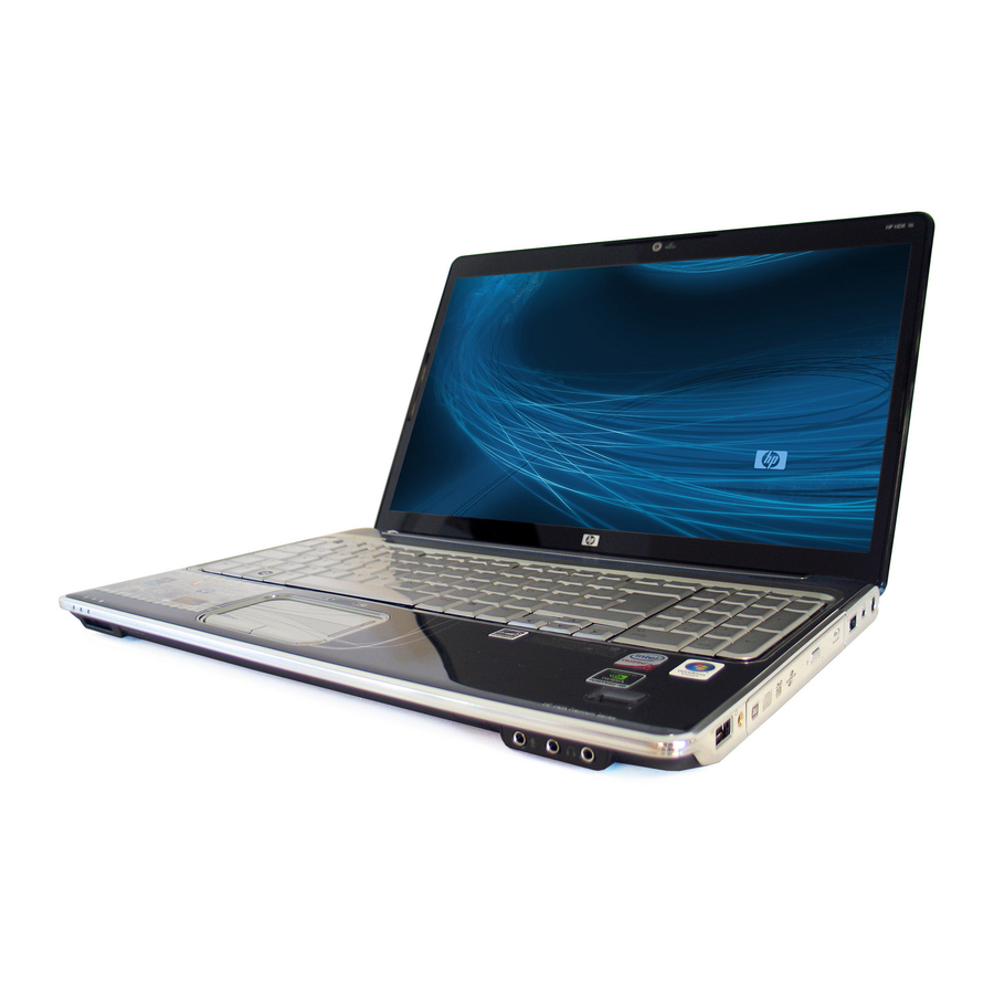
HP HDX 16 Entertainment PC
Maintenance and Service Guide
Document Part Number: 487263-001
November 2008
This guide is a troubleshooting reference used for maintaining and servicing the computer. It provides
comprehensive information on identifying computer features, components, and spare parts; troubleshooting
computer problems; and performing computer disassembly procedures.
Advertisement
Table of Contents

Related Manuals for HP HDX 16


Summary of Contents for HP HDX 16
- Page 1 HP HDX 16 Entertainment PC Maintenance and Service Guide Document Part Number: 487263-001 November 2008 This guide is a troubleshooting reference used for maintaining and servicing the computer. It provides comprehensive information on identifying computer features, components, and spare parts; troubleshooting...
- Page 2 Windows Vista are U.S. registered trademarks of Microsoft Corporation. SD Logo is a trademark of its proprietor. The information contained herein is subject to change without notice. The only warranties for HP products and services are set forth in the express warranty statements accompanying such products and services. Nothing herein should be construed as constituting an additional warranty.
- Page 3 Safety warning notice WARNING: To reduce the possibility of heat-related injuries or of overheating the computer, do not place the computer directly Å on your lap or obstruct the computer air vents. Use the computer only on a hard, flat surface. Do not allow another hard surface, such as an adjoining optional printer, or a soft surface, such as pillows or rugs or clothing, to block airflow.
-
Page 4: Table Of Contents
1 Product description 2 External component identification Top components ..............2–1 Display components . - Page 5 Switch cover ..............4–18 Keyboard cover .
- Page 6 7 Screw listing Phillips PM2.5×7.0 screw ............. . 7–1 Phillips PM2.0×4.0 screw .
-
Page 7: Product Description
Panel Memory Product description Description HP HDX 16 Entertainment PC Intel® Core™2 Duo processors: ■ T9600 2.80-GHz processor, 6-MB L2 cache, 1066-MHz front side bus (FSB) ■ T9500 2.53-GHz processor, 6-MB L2 cache, 1066-MHz FSB ■ T8600 2.40-GHz processor, 3-MB L2 cache, 1066-MHz FSB ■... - Page 8 Hard drives Optical drives Microphone Product description Description Supports 9.50-mm, 6.35-cm (2.50-inch) hard drives Supports second hard drive Supports HP 3D DriveGuard protection Customer-accessible Serial ATA Supports the following hard drives: ■ 500-GB, 5400-rpm ■ 400-GB, 5400-rpm ■ 320-GB, 7200-rpm ■...
- Page 9 Category Audio Webcam Modem Ethernet Wireless TV tuner External media cards Product description Description High-definition audio Integrated subwoofer Supports Microsoft® premium requirements 2 Altec Lansing Pavilion-branded speakers Low-light VGA camera Fixed (no tilt) Activity LED 640 × 480 by 30 24 frames per second 56K V.92 1.5-inch data/fax modem with digital line guard Modem cable is not included...
- Page 10 Category Ports Docking Keyboard/pointing devices Power requirements Security Operating system Serviceability Product description Description 1394 Audio-in (mono microphone) Audio-out (stereo headphones, 2) Consumer infrared eSATA HDMI Multi-pin AC power RJ-45 (Ethernet, includes link and activity lights) TV tuner USB (3) VGA (Dsub 15-pin) supporting 1600 ×...
-
Page 11: External Component Identification
Top components Display components Item Component Internal display switch Wireless antennae (2) Internal digital dual-array microphones (2) Integrated webcam light Integrated webcam ✎ To see wireless regulatory notices, refer to the section of the Regulatory, Safety and Environmental Notices that applies to your country or region. -
Page 12: Buttons, Speakers, And Fingerprint Reader
Buttons, speakers, and fingerprint reader Item Component Power button* Speakers (2) Media button Previous/rewind button Stop button Play/pause button Next/fast forward button Optical drive button Volume mute button External component identification Function ■ When the computer is off, press the button to turn on the computer. ■... - Page 13 Item Component Volume scroll zone Treble/bass button Treble or bass volume scroll zone Wireless button Fingerprint reader *This table describes factory settings. For information about changing factory settings, refer to the user guides located in Help and Support. External component identification Function Adjusts speaker volume.
-
Page 14: Keys
Keys Item Component esc key fn key Windows logo key Windows applications key Integrated numeric keypad keys Function keys External component identification Function Displays system information when pressed in combination with the fn key. Executes frequently used system functions when pressed in combination with a function key or the esc key. -
Page 15: Lights
On: Num lock is on or the embedded numeric keypad is enabled. ■ Blinking: The hard drive or optical drive is being accessed. ■ Amber: HP ProtectSmart Hard Drive Protection has temporarily parked the internal hard drive. ■ On: A battery is charging. -
Page 16: Pointing Devices
Pointing devices Item Component TouchPad light TouchPad* Left TouchPad button* TouchPad on/off button TouchPad scroll zone Right TouchPad button* *This table describes factory settings. To view or change pointing device references, select Start > Control Panel > Hardware and Sound > Mouse. External component identification Function ■... -
Page 17: Front Components
■ Secure Digital (SD) Memory Card ■ xD-Picture Card (XD) On: A digital card is being accessed. Receives a signal from the HP Remote Control (select models only). Connects an optional computer headset microphone, stereo array microphone, or monaural microphone. -
Page 18: Left-Side Components
Left-side components Item Component External monitor port Expansion port 3 RJ-45 (network) jack HDMI port eSATA/USB port USB port 1394 port ExpressCard slot Rear component Component Vent External component identification Function Connects an external VGA monitor or projector. Connects the computer to an optional docking device or optional expansion product. -
Page 19: Bottom Components
Bottom components Item Component Subwoofer Battery bay Battery release latch Vents (7) Hard drive bay WLAN module compartment External component identification Function Contains the subwoofer speaker. Holds the battery. Releases the battery from the battery bay. Enable airflow to cool internal components. ✎... -
Page 20: Illustrated Parts Catalog
Service tag When ordering parts or requesting information, provide the computer serial number and model description provided on the service tag. Item Component Product name Serial number (s/n) Part number/Product number (p/n) Model description Warranty period Illustrated parts catalog Illustrated parts catalog Description This is the product name affixed to the front of the computer. -
Page 21: Computer Major Components
Computer major components Illustrated parts catalog 3–2... - Page 22 Item Description Display assembly (includes 2 WLAN antenna transceivers and cables, webcam, microphones, and logo) 16.0-inch, WXGA, AntiGlare, FHD, dual lamp with webcam and microphone 16.0-inch, WXGA, AntiGlare, HD, dual lamp with webcam and microphone 16.0-inch, WXGA, AntiGlare, HD, single lamp with webcam and microphone ✎...
- Page 23 Item Description (9a) Base enclosure, includes: (9b) Subwoofer (9c) Power connector cable Power connector cable bracket (not illustrated) Fan (see also item 16) 5 rubber feet (not illustrated) Rubber Feet Kit (not illustrated, includes 5 rubber feet) (10) Top cover (includes fingerprint reader board, fingerprint reader board cable, TouchPad, and TouchPad cables) (11) TouchPad on/off button board (incudes cable)
- Page 24 Item Description (21) Optical drive (includes bezel and optical drive bracket) Blu-ray ROM DVD±RW SuperMulti DL Drive with LightScribe Blu-ray ROM DVD±RW SuperMulti DL Drive Blu-ray ROM DVD±RW Drive DVD±RW and CD-RW SuperMulti Double-Layer Combo Drive with LightScribe (22) Hard drive (includes left and right hard drive brackets, Mylar sleeve, connector, and isolators) 500-GB, 5400-rpm 400-GB, 5400-rpm 320-GB, 7200-rpm...
- Page 25 Item Description (26) WLAN module: ■ Atheros AR9280 802.11a/b/g/n WLAN module for use in Antigua and Barbuda, Barbados, Belize, Canada, the Cayman Islands, Guam, Puerto Rico, Trinidad and Tobago, the U.S. Virgin Islands, and the United States ■ Atheros AR9280 802.11a/b/g/n WLAN module for use in Afghanistan, Albania, Algeria, Andorra, Angola, Antigua and Barbuda, Argentina, Armenia, Aruba, Australia, Austria, Azerbaijan, the Bahamas, Bahrain, Bangladesh, Barbados, Belarus, Belgium, Belize, Benin, Bermuda, Bhutan, Bolivia, Bosnia and Herzegovina, Botswana, Brazil,...
-
Page 26: Plastics Kit
Plastics Kit Item Description Plastics Kit ExpressCard slot bezel Hard drive cover (includes four captive screws, secured by C-clips) WLAN module compartment cover (includes one captive screw, secured by a C-clip) Illustrated parts catalog Spare part number 496477-001 3–7... -
Page 27: Display Assembly Components
Display assembly components Illustrated parts catalog 3–8... - Page 28 Item Description Display enclosure Display Cable Kit, includes: (2a) Wireless antenna transceivers and cables (2b) Webcam/microphone module cable (2c) Display panel cable For use only with dual-lamp display assemblies For use only with single-lamp display assemblies Display hinge cover Display Hinge Kit, includes: (4a) Display hinge bracket (4b)
-
Page 29: Mass Storage Devices
Mass storage devices Item Description Hard drives (include left and right hard drive brackets, Mylar sleeve, connector, and isolators): 500-GB, 5400-rpm 400-GB, 5400-rpm 320-GB, 7200-rpm 320-GB, 5400-rpm 250-GB, 5400-rpm 160-GB, 7200-rpm 160-GB, 5400-rpm Optical drives (include bezel and optical drive bracket): Blu-ray ROM DVD±RW SuperMulti DL Drive with LightScribe Blu-ray ROM DVD±RW SuperMulti DL Drive Blu-ray ROM DVD±RW Drive... -
Page 30: Miscellaneous Parts
Miscellaneous parts Description AC adapters 90-W AC adapter for use in all countries and regions except Germany 90-W AC adapter for use only in Germany 65-W AC adapter Bluetooth laser mouse Power cords: For use in Argentina For use in Australia For use in Brazil For use in Denmark For use in Europe, the Middle East, and Africa... -
Page 31: Sequential Part Number Listing
Sequential part number listing Spare part number Description 371693-001 Wired headset with volume control 449729-001 RTC battery 455916-002 Bluetooth laser mouse 463955-001 90-W AC adapter for use in all countries and regions except Germany 463958-001 65-W AC adapter 465540-001 Full function remote control without teletext 465541-002 Full function remote control with teletext 480985-001... - Page 32 Spare part number Description 482899-002 DVB-T/ANG TV tuner module ✎ 482899-003 DVB-T TV tuner module ✎ 482900-001 TV tuner external antenna cable with PAL jack 482900-002 TV tuner external antenna cable with F-PAL jack 483113-001 Bluetooth module ✎ 488317-001 Display inverter for use with display assemblies equipped with dual-lamp inverters 490371-001 Power cord for use in the United States 490371-011...
- Page 33 Spare part number Description 496468-001 16.0-inch, WXGA, AntiGlare, HD display assembly dual-lamp with webcam and microphone (includes 2 WLAN antenna transceivers and cables, webcam, microphones, and logo) 496469-001 Base enclosure (includes fan, power connector cable, power connector cable bracket, subwoofer, and 5 rubber feet) 496470-001 Top cover (includes fingerprint reader board, fingerprint reader board cable, TouchPad, and...
- Page 34 Spare part number Description 496674-001 Webcam/microphone module 497692-001 1024-MB memory module (667-MHz, PC2-6400, 1-DIMM) 497693-001 2048-MB memory module (667-MHz, PC2-6400, 1-DIMM) 497694-001 6-cell, 2.55-Ah Li-ion battery for use in all countries and regions except Germany 497694-002 6-cell, 2.55-Ah Li-ion battery for use only in Germany 497695-001 12-cell, 8.80-Ah Li-ion battery 497936-001...
- Page 35 Spare part number Description 505856-001 250-GB, 5400-rpm hard drive (includes left and right hard drive brackets, Mylar sleeve, connector, and isolators) 505857-001 320-GB, 7200-rpm hard drive (includes left and right hard drive brackets, Mylar sleeve, connector, and isolators) 506591-001 4096-MB memory module (667-MHz, PC2-6400, 1-DIMM) 507951-001 Intel Core2 Duo T9800 2.93-GHz processor with 6-MB L2 cache and 1066-MHz FSB (includes replacement thermal material)
-
Page 36: Removal And Replacement Procedures
Preliminary replacement requirements Tools required You will need the following tools to complete the removal and replacement procedures: ■ Flat-bladed screwdriver ■ Magnetic screwdriver ■ Phillips P0 and P1 screwdrivers Service considerations The following sections include some of the considerations that you must keep in mind during disassembly and assembly procedures. -
Page 37: Drive Handling
Drive handling Ä CAUTION: Drives are fragile components that must be handled with care. To prevent damage to the computer, damage to a drive, or loss of information, observe these precautions: ■ Before removing or inserting a hard drive, shut down the computer. If you are unsure whether the computer is off or in Hibernation, turn the computer on, and then shut it down through the operating system. -
Page 38: Packaging And Transporting Guidelines
The following table shows how humidity affects the electrostatic voltage levels generated by different activities. CAUTION: A product can be degraded by as little as 700 V. Ä Typical electrostatic voltage levels Event Walking across carpet Walking across vinyl floor Motions of bench worker Removing DIPS from plastic tube Removing DIPS from vinyl tray... -
Page 39: Workstation Guidelines
Workstation guidelines Follow these grounding workstation guidelines: ■ Cover the workstation with approved static-shielding material. ■ Use a wrist strap connected to a properly grounded work surface and use properly grounded tools and equipment. ■ Use conductive field service tools, such as cutters, screwdrivers, and vacuums. ■... -
Page 40: Unknown User Password
The following table lists the shielding protection provided by antistatic bags and floor mats. Material Antistatic plastic Carbon-loaded plastic Metallized laminate Unknown user password If the computer you are servicing has an unknown user password, follow these steps to clear the password: ✎... -
Page 41: Component Replacement Procedures
Component replacement procedures This chapter provides removal and replacement procedures. There are as many as 85 screws, in 7 different sizes, that must be removed, replaced, or loosened when servicing the computer. Make special note of each screw size and location during removal and replacement. Service tag When ordering parts or requesting information, provide the computer serial number and model description provided on the service tag. -
Page 42: Computer Feet
Computer feet The computer feet are adhesive-backed rubber pads. The feet are included in the Rubber Feet Kit, spare part number 496478-001. There are 5 rubber feet, in two different sizes (1 and 2), that attach to the base enclosure in the locations illustrated below. -
Page 43: Battery
Battery Description 12-cell, 8.80-Ah Li-ion 6-cell, 2.55-Ah Li-ion for use in all countries and regions except Germany 6-cell, 2.55-Ah Li-ion for use only in Germany Before disassembling the computer, follow these steps: 1. Shut down the computer. If you are unsure whether the computer is off or in Hibernation, turn the computer on, and then shut it down through the operating system. -
Page 44: Optical Drive
Optical drive ✎ The optical drive spare part kit includes an optical drive bezel and bracket. Description Blu-ray ROM DVD±RW SuperMulti DL Drive with LightScribe Blu-ray ROM DVD±RW SuperMulti DL Drive Blu-ray ROM DVD±RW Drive DVD±RW and CD-RW SuperMulti Double-Layer Combo Drive with LightScribe Before removing the optical drive, follow these steps: 1. - Page 45 5. If it is necessary to replace the optical drive bracket: a. Position the optical drive with the rear toward you. b. Remove the two Phillips PM2.0×4.0 screws 1 that secure the optical drive bracket to the optical drive. c. Remove the optical drive bracket 2. Reverse this procedure to reassemble and install an optical drive.
-
Page 46: Hard Drive
Hard drive ✎ The hard drive spare part kit includes a left and right hard drive bracket, Mylar sleeve, connector, and four isolators. Description 500-GB, 5400-rpm 400-GB, 5400-rpm 320-GB, 7200-rpm 320-GB, 5400-rpm 250-GB, 5400-rpm 160-GB, 7200-rpm 160-GB, 5400-rpm Before removing the hard drive, follow these steps: 1. - Page 47 3. Disconnect the hard drive cable 1 from the system board. 4. Grasp the Mylar tabs 2 on the hard drive and slide the hard drive 3 to the left. 5. Remove the hard drive from the hard drive bay 4. 6.
-
Page 48: Tv Tuner Module
TV tuner module Description DVB-T TV tuner module DVB-T/ANG TV tuner module NTSC/ATSC/ANG TV tuner module Before removing the TV tuner module, follow these steps: 1. Shut down the computer. If you are unsure whether the computer is off or in Hibernation, turn the computer on, and then shut it down through the operating system. -
Page 49: Rtc Battery
RTC battery ✎ Removing the RTC battery and leaving it uninstalled for 5 or more minutes causes all passwords and CMOS settings to be cleared. Description RTC battery Before removing the RTC battery, follow these steps: 1. Shut down the computer. If you are unsure whether the computer is off or in Hibernation, turn the computer on, and then shut it down through the operating system. -
Page 50: Memory Module
Memory module Description 4096-MB (667-MHz, PC2-6400, 1-DIMM) 2048-MB (667-MHz, PC2-6400, 1-DIMM) 1024-MB (667-MHz, PC2-6400, 1-DIMM) Before removing the memory module, follow these steps: 1. Shut down the computer. If you are unsure whether the computer is off or in Hibernation, turn the computer on, and then shut it down through the operating system. -
Page 51: Wlan Module
WLAN module Description Atheros AR9280 802.11a/b/g/n WLAN module for use in Antigua and Barbuda, Barbados, Belize, Canada, the Cayman Islands, Guam, Puerto Rico, Trinidad and Tobago, the U.S. Virgin Islands, and the United States Atheros AR9280 802.11a/b/g/n WLAN module for use in Afghanistan, Albania, Algeria, Andorra, Angola, Antigua and Barbuda, Argentina, Armenia, Aruba, Australia, Austria, Azerbaijan, the Bahamas, Bahrain, Bangladesh, Barbados, Belarus, Belgium, Belize, Benin, Bermuda, Bhutan, Bolivia, Bosnia and Herzegovina, Botswana, Brazil, the British Virgin Islands, Brunei, Bulgaria,... - Page 52 Remove the WLAN module: 1. Loosen the Phillips PM2.5×6.0 captive screw 1 that secures the WLAN module compartment cover to the computer. 2. Lift the right side of the WLAN module compartment cover 2, swing it up and to the left, and then remove the cover 3.
-
Page 53: Switch Cover
Switch cover Description Switch cover Before removing the switch cover, follow these steps: 1. Shut down the computer. If you are unsure whether the computer is off or in Hibernation, turn the computer on, and then shut it down through the operating system. 2. - Page 54 2. Turn the computer display-side up, with the front toward you. 3. Open the computer as far as possible. 4. Lift the right side of the switch cover 1 until it detaches from the computer. 5. Remove the switch cover 2 by lifting it straight up. Reverse this procedure to install the switch cover.
-
Page 55: Keyboard Cover
Keyboard cover Description Keyboard cover (includes LED board and cable) Before removing the keyboard cover, follow these steps: 1. Shut down the computer. If you are unsure whether the computer is off or in Hibernation, turn the computer on, and then shut it down through the operating system. 2. - Page 56 3. Turn the computer display-side up, with the front toward you. 4. Open the computer as far as possible. 5. Release the keyboard cover by lifting the front edge 1 until it rests at an angle. 6. Lift the keyboard cover 2 as far as the power button board cable allows. 7.
-
Page 57: Power Button Board
Power button board Description Power button board (includes cable) Before removing the power button board, follow these steps: 1. Shut down the computer. If you are unsure whether the computer is off or in Hibernation, turn the computer on, and then shut it down through the operating system. 2. -
Page 58: Bluetooth Module
Bluetooth module ✎ The Bluetooth module spare part kit does not include a Bluetooth module cable. The Bluetooth module cable is available using spare part number 496461-001. See module cable removal information. Description Bluetooth module Before removing the Bluetooth module, follow these steps: 1. -
Page 59: Keyboard
Keyboard Description For use in Denmark, Finland, and Norway For use in France For use in French Canada For use in Germany For use in Greece For use in Italy For use in Japan For use in Latin America For use in the Netherlands For use in Russia For use in Saudi Arabia For use in South Korea... - Page 60 Remove the keyboard: 1. Turn the computer upside down, with the front toward you. 2. Remove the two Phillips PM2.5×7.0 screws that secure the keyboard to the computer. 3. Turn the computer display-side up, with the front toward you. 4. Open the computer as far as possible. 5.
- Page 61 6. Lift the rear edge of the keyboard 1 until it rests at an angle. 7. Release the keyboard 2 by sliding it back to disengage the tabs on the front edge of the keyboard from the top cover and rest it on the display. 8.
-
Page 62: Power Button Board Cable
Power button board cable ✎ The power button board cable is included with the power button board, spare part number 496482-001. Before removing the power button board cable, follow these steps: 1. Shut down the computer. If you are unsure whether the computer is off or in Hibernation, turn the computer on, and then shut it down through the operating system. -
Page 63: Bluetooth Module Cable
Bluetooth module cable Description Bluetooth module cable Before removing the Bluetooth module cable, follow these steps: 1. Shut down the computer. If you are unsure whether the computer is off or in Hibernation, turn the computer on, and then shut it down through the operating system. 2. -
Page 64: Led Board Cable
LED board cable ✎ The LED board cable is included with the keyboard cover, spare part number 496472-001. Before removing the LED board cable, follow these steps: 1. Shut down the computer. If you are unsure whether the computer is off or in Hibernation, turn the computer on, and then shut it down through the operating system. -
Page 65: Speaker Assembly
Speaker assembly Description Speaker assembly Before removing the speaker assembly, follow these steps: 1. Shut down the computer. If you are unsure whether the computer is off or in Hibernation, turn the computer on, and then shut it down through the operating system. 2. -
Page 66: Display Assembly
Display assembly The display assembly spare part kit includes 2 WLAN antenna transceivers and cables, webcam, microphones, and logo. Description 16.0-inch, WXGA, AntiGlare, FHD, dual-lamp 16.0-inch, WXGA, AntiGlare, HD, dual-lamp 16.0-inch, WXGA, AntiGlare, HD, single-lamp Before removing the display assembly, follow these steps: 1. - Page 67 Remove the display assembly: 1. Open the computer as far as possible. 2. Disconnect the display panel cable 1 from the system board. 3. Disconnect the webcam/microphone module cable 2 from the system board. 4. Remove the WLAN antenna cables 3 from the opening in the routing channel built into the top cover. Removal and replacement procedures 4–32...
- Page 68 Ä CAUTION: Support the display assembly when removing the following screws. Failure to support the display assembly can result in damage to the display assembly and other computer components. 5. Remove the four Phillips PM2.5×7.0 screws 1 that secure the display assembly to the computer. 6.
- Page 69 8. Turn the display assembly upside down, with the bottom edge toward you. 9. Release the display enclosure bottom edge 1 as far as the wireless antenna cables and display logo LED cable allow. 10. Remove the wireless antenna cables 2 from the slot built into the display hinge cover. 11.
- Page 70 16. If it is necessary to replace the webcam/microphone module, remove the Phillips PM2.0×4.0 screw 1 that secures the module to the display bezel. 17. Release the webcam/microphone module 2 as far from the display bezel as the webcam/microphone module cable allows.
- Page 71 21. If it is necessary to replace the webcam/microphone module cable, remove the cable from the display panel. The webcam/microphone module cable is included in the Display Cable Kits, spare part numbers 496465-001 (for use only with dual-lamp display assemblies) and 514289-001 (for use only with single-lamp display assemblies).
- Page 72 26. If it is necessary to replace the display inverter, release the display inverter 1 as far from the display bezel as the backlight cables and display panel cable allow. ✎ Dual-lamp display assemblies will have two cables that must be disconnected in step 27. Single-lamp display assemblies will only have one cable that must be disconnected.
- Page 73 28. If it is necessary to replace the display hinges, remove the two Phillips PM2.0×4.0 screws 1 that secure the display hinge bracket to the display bezel. 29. Remove the display hinge bracket 2. 30. Remove the four Phillips PM2.0×4.0 screws 1 that secure the display hinges to the display panel. 31.
-
Page 74: Top Cover
Top cover Description Top cover (includes fingerprint reader board, fingerprint reader board cable, TouchPad, and TouchPad cables) Before removing the top cover, follow these steps: 1. Shut down the computer. If you are unsure whether the computer is off or in Hibernation, turn the computer on, and then shut it down through the operating system. - Page 75 Remove the top cover: 1. Turn the computer upside down, with the front toward you. 2. Remove the 10 Phillips PM2.5×7.0 screws that secure the top cover to the base enclosure. 3. Remove the three Phillips PM2.0×4.0 screws that secure the top cover to the base enclosure. Removal and replacement procedures 4–40...
- Page 76 4. Turn the computer right-side up, with the front toward you. 5. Disconnect the following cables from the system board: 1 TouchPad board cable 2 TouchPad on/off button board cable 6. Remove the Phillips PM2.0×4.0 screw that secures the top cover to the base enclosure. Removal and replacement procedures 4–41...
- Page 77 7. Lift the rear edge 1 of the top cover until it rests at an angle. 8. Slide the top cover 2 back until the fingerprint reader board cable is accessible. 9. Disconnect the fingerprint reader board cable 1 from the LIF connector on the system board. 10.
-
Page 78: Touchpad On/Off Button Board
TouchPad on/off button board Description TouchPad on/off button board (incudes cable) Before removing the TouchPad on/off button board, follow these steps: 1. Shut down the computer. If you are unsure whether the computer is off or in Hibernation, turn the computer on, and then shut it down through the operating system. - Page 79 Remove the TouchPad on/off button board: 1. Turn the top cover upside down, with the front toward you. 2. Remove the Phillips PM2.0×4.0 screw 1 that secures the TouchPad on/off button board to the top cover. 3. Remove the TouchPad on/off button board 2 and cable. Reverse this procedure to install the TouchPad on/off button board.
-
Page 80: System Board
System board Description System board (includes 512 MB of graphics subsystem memory and replacement thermal material) 496460-001 Before removing the system board, follow these steps: 1. Shut down the computer. If you are unsure whether the computer is off or in Hibernation, turn the computer on, and then shut it down through the operating system. - Page 81 Remove the system board: 1. Turn the computer upside down, with the front toward you. 2. Disconnect the subwoofer cable from the system board. 3. Turn the computer right-side up, with the front toward you. 4. Disconnect the following cables from the system board: 1 Fan cable 2 Audio/infrared board cable 3 Power connector cable...
- Page 82 5. Remove the three Phillips PM2.0×4.0 screws that secure the system board to the base enclosure. 6. Use the optical drive connector 1 to lift the right side 2 of the system board until it rests at an angle. 7. Remove the system board 3 by sliding it up and to the right. Reverse this procedure to install the system board.
-
Page 83: Fan
Description ✎ The fan is also available with the base enclosure spare part kit, spare part 496469-001. Before removing the fan, follow these steps: 1. Shut down the computer. If you are unsure whether the computer is off or in Hibernation, turn the computer on, and then shut it down through the operating system. - Page 84 Remove the fan: 1. Remove the two Phillips PM2.0×4.0 screws 1 that secure the fan to the base enclosure. 2. Remove the fan 2 by lifting it straight up. Reverse this procedure to install the fan. Removal and replacement procedures 4–49...
-
Page 85: Audio/Infrared Board
Audio/infrared board Description Audio/infrared board (includes cable) Before removing the audio/infrared board, follow these steps: 1. Shut down the computer. If you are unsure whether the computer is off or in Hibernation, turn the computer on, and then shut it down through the operating system. 2. - Page 86 Remove the audio/infrared board: 1. Disconnect the audio/infrared board cable 1 from the system board. 2. Remove the two Phillips PM2.0×4.0 screws 2 that secure the audio/infrared board to the base enclosure. 3. Remove the audio/infrared board 3 by lifting it straight up. Reverse this procedure to install the audio/infrared board.
-
Page 87: Tv Tuner Module Cable
TV tuner module cable ✎ The TV tuner module cable is included in the Cable Kit, spare part number 496481-001. Before removing the TV tuner module cable, follow these steps: 1. Shut down the computer. If you are unsure whether the computer is off or in Hibernation, turn the computer on, and then shut it down through the operating system. -
Page 88: Usb Board
USB board Description USB board (includes cable) Before removing the USB board, follow these steps: 1. Shut down the computer. If you are unsure whether the computer is off or in Hibernation, turn the computer on, and then shut it down through the operating system. 2. -
Page 89: Power Connector Cable
Power connector cable ✎ The power connector cable is included in the base enclosure spare part kit, spare part number 496469-001. Before removing the power connector cable, follow these steps: 1. Shut down the computer. If you are unsure whether the computer is off or in Hibernation, turn the computer on, and then shut it down through the operating system. - Page 90 Remove the power connector cable: 1. Disconnect the power connector cable 1 from the system board. 2. Remove the Phillips PM2.5×7.0 screw 2 that secures the power connector and bracket to the base enclosure. 3. Remove the power connector bracket 3. 4.
-
Page 91: Subwoofer
Subwoofer ✎ The subwoofer is included in the base enclosure spare part kit, spare part number 496469-001. Before removing the subwoofer, follow these steps: 1. Shut down the computer. If you are unsure whether the computer is off or in Hibernation, turn the computer on, and then shut it down through the operating system. - Page 92 Remove the subwoofer: 1. Remove the subwoofer cable 1 from the clips 2 and routing channel built into the base enclosure. 2. Remove the two Phillips PM2.5×5.0 broadhead screws 3 that secure the subwoofer to the base enclosure. ✎ The rubber grommets grommets are critical for satisfactory subwoofer performance.
-
Page 93: Fan/Heat Sink Assembly
Fan/heat sink assembly Description Fan/heat sink assembly (includes replacement thermal material) ✎ To properly ventilate the computer, allow at least a 7.6-cm (3-inch) clearance on the left side of the computer. The computer uses an electric fan for ventilation. The fan is controlled by a temperature sensor and is designed to turn on automatically when high temperature conditions exist. - Page 94 Remove the fan/heat sink assembly: 1. Disconnect the fan cable 1 from the system board. 2. Loosen the four Phillips PM2.5×11.0 captive screws 2 and the two Phillips PM2.5×5.0 captive screws 3 that secure the fan/heat sink assembly to the system board. ✎...
- Page 95 ✎ The thermal material must be thoroughly cleaned from the surfaces of the fan/heat sink assembly, the system board, and the processor each time the fan/heat sink assembly is removed: ■ Thermal paste is used on the processor 1 and the heat sink section 2 that services it. ■...
-
Page 96: Processor
Processor ✎ The processor spare part kit includes replacement thermal material. Description Intel Core2 Duo T9800 2.93-GHz processor with 6-MB L2 cache and 1066-MHz FSB Intel Core2 Duo T9600 2.80-GHz processor with 6-MB L2 cache and 1066-MHz FSB Intel Core2 Duo T9550 2.66-GHz processor with 6-MB L2 cache and 1066-MHz FSB Intel Core2 Duo T9500 2.53-GHz processor with 6-MB L2 cache and 1066-MHz FSB Intel Core2 Duo T8700 2.53-GHz processor with 3-MB L2 cache and 1066-MHz FSB Intel Core2 Duo T8600 2.40-GHz processor with 3-MB L2 cache and 1066-MHz FSB... - Page 97 Remove the processor: 1. Turn the processor locking screw 1 one-half turn counterclockwise until you hear a click. 2. Lift the processor 2 straight up and remove it. ✎ The gold triangle 3 on the processor must be aligned with the triangle icon 4 embossed on the processor socket when you install the processor.
-
Page 98: Setup Utility
The Setup Utility is a ROM-based information and customization utility that can be used even when your Windows operating system is not working. The utility reports information about the computer and provides settings for startup, security, and other preferences. ✎ The fingerprint reader (select models only) does not work when accessing the Setup Utility. -
Page 99: Displaying System Information
Displaying system information The following procedure explains how to display system information in the Setup Utility. If the Setup Utility is not open, begin at step 1. If the Setup Utility is open, begin at step 2. 1. To start the Setup Utility, turn on or restart the computer, and then press is displayed in the lower-left corner of the screen. -
Page 100: Setup Utility Menus
Setup Utility menus The menu tables in this section provide an overview of Setup Utility options. ✎ Some of the Setup Utility menu items listed in this chapter may not be supported by your computer. Main menu Select System information Security menu Select Administrator password... -
Page 101: Diagnostics Menu
Diagnostics menu Select Hard Disk Self Test Secondary Hard Disk Self Test (select models only) Memory Test Setup Utility To Do This Run a comprehensive self-test on the hard drive. ✎ On models with two hard drives, this menu option is called the Primary Hard Disk Self Test. -
Page 102: Specifications
Computer specifications Dimensions Length Width Height (front to rear) Weight Input power Operating voltage Operating current Temperature Operating (not writing to optical disc) Operating (writing to optical disc) Nonoperating Relative humidity Operating Nonoperating Maximum altitude (unpressurized) Operating Nonoperating ✎ Applicable product safety standards specify thermal limits for plastic surfaces. The computer operates well within this range of temperatures. -
Page 103: 16.0-Inch Fhd Display Specifications
16.0-inch FHD display specifications Dimensions Height Width Diagonal Number of colors Contrast ratio Brightness Pixel resolution Pitch Format Configuration Backlight Character display Total power consumption Viewing angle 16.0-inch HD display specifications Dimensions Height Width Diagonal Number of colors Contrast ratio Brightness Pixel resolution Pitch... -
Page 104: Hard Drive Specifications
Hard drive specifications Dimensions Height Width Weight Interface type Transfer rate Security Seek times (typical read, including setting) Single track Average Maximum Logical blocks Disc rotational speed Operating temperature *1 GB = 1 billion bytes when referring to hard drive storage capacity. Actual accessible capacity is less. Actual drive specifications may differ slightly. - Page 105 Hard drive specifications (Continued) Dimensions Height Width Weight Interface type Transfer rate Security Seek times (typical read, including setting) Single track Average Maximum Logical blocks Disc rotational speed Operating temperature *1 GB = 1 billion bytes when referring to hard drive storage capacity. Actual accessible capacity is less. Actual drive specifications may differ slightly.
-
Page 106: Blu-Ray Rom Dvd±Rw Supermulti Dl Drive Specifications
Blu-ray ROM DVD±RW SuperMulti DL Drive specifications Applicable disc Access time Random Cache buffer Data transfer rate 2X BD-RAM 8X DVD 16X CD-R 16X CD-RW Specifications Read: Write: BD-ROM, BD-ROM-DL, BD-R, DVD-RAM (Ver.2), DVD+R, BD-R-DL, BD-RE, BD-RE-DL, DVD-R, CD-R, and CD-RW DVD-ROM, DVD+R, DVD+R-DL, DVD+RW, DVD-R, DVD-R-DL, DVD-RW,... -
Page 107: Dvd±Rw And Cd-Rw Supermulti Double-Layer Combo Drive Specifications
DVD±RW and CD-RW SuperMulti Double-Layer Combo Drive specifications Applicable disc Access time Random Cache buffer Data transfer rate 24X CD-ROM 8X DVD 24X CD-R 16X CD-RW 8X DVD+R 4X DVD+RW 8X DVD-R 4X DVD-RW 2.4X DVD+R(9) 5X DVD RAM Specifications Read: Write: CD-DA, CD+(E)G, CD-MIDI,... -
Page 108: System Dma Specifications
System DMA specifications Hardware DMA0 DMA1* DMA2* DMA3 DMA4 DMA5* DMA6 DMA7 *PC Card controller can use DMA 1, 2, or 5. System memory map specifications Size 640 KB 128 KB 64 KB 64 KB Specifications DMA System function Not applicable Not applicable Not applicable Not applicable... -
Page 109: System Interrupt Specifications
System interrupt specifications Hardware IRQ IRQ0 IRQ1 IRQ2 IRQ3 IRQ4 IRQ5* IRQ6 IRQ7* IRQ8 IRQ9* IRQ10* IRQ11 IRQ12 IRQ13 IRQ14 IRQ15 IRQ16 IRQ17 IRQ18 IRQ19 IRQ20 IRQ21 IRQ22 *Default configuration; audio possible configurations are IRQ5, IRQ7, IRQ9, IRQ10, or none. ✎... -
Page 110: System I/O Address Specifications
System I/O address specifications I/O address (hex) 000 - 01F 020 - 021 024 - 025 028 - 029 02C - 03D 02E - 02F 030 - 031 034 - 035 038 - 039 03C- 03D 040 - 043 04E-04F 050-053 071-077 081-091... - Page 111 I/O address (hex) 0C0- 0DF 0F0- 0F0 0200-027F 3B0-3BB 3C0-3DF 400-47F 4D0-4D1 500-57F 1000-1003 1010-101F 2000-20FF 2000-2FFF 3000-4FFF 5000-6FFF 7000-701F 7020-703F 7040-705F 7060-707F 7080-709F 70A0-70BF 70C0-70DF 70E0-70E7 70E8-70EF 70F0-70F7 70F8-70FB 70FC-70FF EF80-EF9F FE00-FE0F FE80-EF8F FFFF Specifications System function (shipping configuration) Direct memory access controller Numeric data processor Motherboard resources...
-
Page 112: Screw Listing
This section provides specification and reference information for the screws used in the computer. The screws listed in this section are available in the Screw Kit, spare part number 496479-001. Phillips PM2.5×7.0 screw Color Quantity Black Where used: One screw that secures the optical drive to the computer Screw listing Length Thread... - Page 113 Where used: 1 Two screws that secure the switch cover to the computer 2 Two screws that secure the keyboard to the computer Where used: 4 screws that secure the display assembly to the computer Where used: 4 screws that secure the display enclosure to the display assembly Screw listing 7–2...
- Page 114 Where used: 4 screws that secure the display hinges to the display panel Where used: 10 screws that secure the top cover to the base enclosure Where used: One screw that secures the power connector bracket to the base enclosure Screw listing 7–3...
-
Page 115: Phillips Pm2.0×4.0 Screw
Phillips PM2.0×4.0 screw Color Quantity Black Where used: 2 screws that secure the optical drive bracket to the optical drive Where used: 1 Two screws that secure the TV tuner module to the system board 2 Two screws that secure the WLAN module to the system board Screw listing Length Thread... - Page 116 Where used: 3 screws that secure the switch cover to the computer Where used: 2 screws that secure the keyboard cover to the computer Where used: 1 One screw that secures the power button board to the top cover 2 One screw that secures the Bluetooth module to the computer 2 One screw that secures the keyboard to the computer Screw listing 7–5...
- Page 117 Where used: 2 screws that secure the wireless antenna transceivers to the display enclosure Where used: One screw that secures the webcam/microphone module to the display panel Where used: 4 screws that secure the display hinge cover to the display panel Screw listing 7–6...
- Page 118 Where used: 2 screws that secure the display hinge bracket to the display panel Where used: 4 screws that secure the display hinges to the display panel Where used: 3 screws that secure the top cover to the base enclosure Screw listing 7–7...
- Page 119 Where used: One screw that secures the top cover to the base enclosure Where used: One screw that secures the TouchPad on/off button board to the top cover Where used: 3 screws that secure the system board to the base enclosure Screw listing 7–8...
- Page 120 Where used: 2 screws that secure the fan to the base enclosure Where used: 2 screws that secure the audio/infrared board to the base enclosure Where used: One screw that secures the USB board to the base enclosure Screw listing 7–9...
-
Page 121: Phillips Pm2.5×6.0 Captive Screw
Phillips PM2.5×6.0 captive screw Color Quantity Black Where used: 1 One captive screw that secures the WLAN module compartment cover to the computer (screw is secured by a C clip) 2 Four captive screws that secure the hard drive cover to the computer (screws are secured by C clips) Screw listing Length Thread... -
Page 122: Phillips Pm3.0×4.0 Screw
Phillips PM3.0×4.0 screw Color Quantity Silver Where used: 4 screws that secure the hard drive left and right brackets to the hard drive Screw listing Length Thread 4.0 mm 3.0 mm Head diameter 5.0 mm 7–1 1... -
Page 123: Phillips Pm2.5×5.0 Broadhead Screw
Phillips PM2.5×5.0 broadhead screw Color Quantity Silver Where used: 2 screws that secure the subwoofer to the base enclosure Screw listing Length Thread 5.0 mm 2.5 mm Head diameter 8.0 mm 7–12... -
Page 124: Phillips Pm2.5×11.0 Captive Screw
Phillips PM2.5×1 1.0 captive screw Color Quantity Silver Where used: 4 captive screws that secure the fan/heat sink assembly to the system board (screws are secured by O rings) Screw listing Length Thread 11.0 mm 2.5 mm Head diameter 6.0 mm 7–13... -
Page 125: Phillips Pm2.5×5.0 Captive Screw
Phillips PM2.5×5.0 captive screw Color Quantity Silver Where used: 2 captive screws that secure the fan/heat sink assembly to the system board (screws are secured by O rings) Screw listing Length Thread 5.0 mm 2.5 mm Head diameter 5.0 mm 7–14... -
Page 126: Backup And Recovery
Creating recovery discs ✎ HP recommends that you create recovery discs to be sure that you can restore your system to its original factory state if you experience serious system failure or instability. Create these discs after setting up the computer for the first time. -
Page 127: Backing Up Your Information
Note the following guidelines before creating recovery discs: ■ You will need high quality CD-R, DVD-R, double-layer DVD-R, DVD+R, double-layer DVD+R, or BD-R (writable Blu-ray) discs. All these discs are purchased separately. ✎ Read-write discs, such as CD-RW, DVD±RW, double-layer DVD±RW, and BD-RE (rewritable Blu-ray) discs, are not compatible with the Recovery Manager software. -
Page 128: Using System Restore Points
Using system restore points When you back up your system, you are creating a system restore point. A system restore point allows you to save and name a snapshot of your hard drive at a specific point in time. You can then recover back to that point if you want to reverse subsequent changes made to your system. -
Page 129: Performing A Recovery
Performing a recovery ✎ You can recover only files that you have previously backed up. HP recommends that you use Recovery Manager to create an entire drive backup as soon as you set up your computer. Recovery Manager software allows you to repair or restore the system if you experience system failure or instability. -
Page 130: Connector Pin Assignments
1394 Audio-in (microphone) Connector pin assignments Connector pin assignments Signal TPB- TPB+ TPA- TPA+ Signal Audio signal in Audio signal in Ground 9–1... -
Page 131: Audio-Out (Headphone)
Audio-out (headphone) External monitor Connector pin assignments Signal Audio out, left channel Audio out, right channel Ground Signal Red analog Green analog Blue analog Not connected Ground Ground analog Ground analog Ground analog +5 VDC Ground Monitor detect DDC 2B data Horizontal sync Vertical sync DDC 2B clock... -
Page 132: Hdmi
HDMI Connector pin assignments Signal Transition minimized differential signal (TDMS) data 2+ TDMS data 2 shield TDMS data 2- TDMS data 1+ TDMS data 1 shield TDMS data 1 shield TDMS data 0+ TDMS data 0 shield TDMS data 0- TDMS clock + TDMS data clock shield TDMS data clock-... -
Page 133: Rj-45 (Network)
RJ-45 (network) Universal Serial Bus Connector pin assignments Signal Transmit + Transmit - Receive + Unused Unused Receive - Unused Unused Signal +5 VDC Data Data + Ground 9–4... -
Page 134: Power Cord Set Requirements
The wide range input feature of the computer permits it to operate from any line voltage from 100 to 120 volts AC or from 220 to 240 volts AC. The 3-conductor power cord set included with the computer meets the requirements for use in the country or region where the equipment is purchased. -
Page 135: Requirements For Specific Countries And Regions
Requirements for specific countries and regions Country/region Australia Austria Belgium Canada Denmark Finland France Germany Italy Japan The Netherlands Norway The People’s Republic of China South Korea Sweden Switzerland Taiwan The United Kingdom The United States 1. The flexible cord must be Type HO5VV-F, 3-conductor, 1.0-mm² conductor size. Power cord set fittings (appliance coupler and wall plug) must bear the certification mark of the agency responsible for evaluation in the country or region where it will be used. -
Page 136: Recycling
✎ Materials disposal. This HP product contains mercury in the backlight in the display assembly that might require special handling at end-of-life. Disposal of mercury may be regulated because of environmental considerations. For disposal or recycling information, contact your local authorities, or see the Electronic Industries Alliance (EIA) Web site at This section provides disassembly instructions for the display assembly. - Page 137 Perform the following steps to disassemble the display assembly: 1. Remove all screw covers 1 and screws 2 that secure the display bezel to the display assembly. 2. Lift up and out on the left and right inside edges 1 and the top and bottom inside edges 2 of the display bezel until the bezel disengages from the display assembly.
- Page 138 4. Disconnect all display panel cables 1 from the display inverter and remove the inverter 2. 5. Remove all screws 1 that secure the display panel assembly to the display enclosure. 6. Remove the display panel assembly 2 from the display enclosure. 7.
- Page 139 9. Use a sharp-edged tool to cut the tape 1 that secures the sides of the display panel to the display panel frame. 10. Remove the display panel frame 2 from the display panel. 11. Remove the screws 1 that secure the backlight cover to the display panel. 12.
- Page 140 16. Turn the display panel upside down. 17. Remove the backlight frame from the display panel. Å WARNING: The backlight contains mercury. Exercise caution when removing and handling the backlight to avoid damaging this component and causing exposure to the mercury. 18.
- Page 141 19. Disconnect the display cable 1 from the LCD panel. 20. Remove the screws 2 that secure the LCD panel to the display rear panel. 21. Release the LCD panel 3 from the display rear panel. 22. Release the tape 4 that secures the LCD panel to the display rear panel. 23.
- Page 142 1394 port connector pinout 9–1 location 2–8 AC adapter, spare part numbers 3–11 administrator password 5–3 advanced Setup Utility features 5–2 antennae disconnecting 4–17 locations 2–1 removal 4–34 audio product description 1–3 audio/infrared board removal 4–50 spare part number 3–4 audio-in jack connector pinout 9–1 location 2–7...
- Page 143 computer specifications 6–1 connector pinout 1394 port 9–1 audio-in jack 9–1 audio-out jack 9–2 external monitor port 9–2 HDMI port 9–3 headphone jack 9–2 microphone jack 9–1 monitor port 9–2 network jack 9–4 RJ-45 jack 9–4 USB port 9–4 Diagnostics menu, Setup Utility 5–4 Digital Media Slot 2–7 Digital Media Slot light 2–7 diskette drive, precautions 4–2...
- Page 144 infrared lens 2–7 integrated numeric keypad keys 2–4 jacks audio-in 2–7 audio-out 2–7 headphone 2–7 microphone 2–7 network 2–8 RJ-45 2–8 TV antenna/cable 2–7 key components 2–4 keyboard product description 1–4 removal 4–24 spare part numbers 3–3 keyboard cover removal 4–20 spare part number 3–3 keys 2–4...
- Page 145 ports 1394 2–8 eSATA/USB 2–8 expansion 3 2–8 external monitor 2–8 HDMI 2–8 monitor 2–8 USB 2–7 2–8 ports product description 1–4 power button 2–2 power button board removal 4–22 spare part number 3–3 power button board cable, removal 4–27 power connector 2–7 power connector cable, removal 4–54 power cord...
- Page 146 system DMA 6–7 system I/O address 6–9 system interrupt 6–8 system memory map 6–7 static-shielding materials 4–3 stop button 2–2 subwoofer location 2–9 removal 4–56 switch cover removal 4–18 spare part number 3–3 system board removal 4–45 spare part number 3–4 System Configuration menu, Setup Utility 5–3 system DMA specifications 6–7 system I/O address specifications 6–9...
Need help?
Do you have a question about the HDX 16 and is the answer not in the manual?
Questions and answers