Table of Contents
Advertisement
Quick Links
Installation and Operation Manual
Web Enabled, Dial-up Four Channel Site Remote Control System
If you need a firmware upgrade, contact Broadcast Tools®
No part of this document may be reproduced or distributed without permission.
ALL SPECIFICATIONS AND FEATURES FOR THIS PRODUCT ARE SUBJECT TO
NOTE: We recommend the use of Chrome, Firefox or Safari as your browser.
Due to the dynamic nature of product design, the information contained in this
document is subject to change without notice. Broadcast Tools, Inc., assumes no
responsibility for errors and/or omissions contained in this document. Revisions
of this information or new editions may be issued to incorporate such changes.
Broadcast Tools® is a registered trademark of Broadcast Tools, Inc.
tiny TOOLS™ is a trademark of Broadcast Tools, Inc.
All Sentinel® labeled products are registered trademarks of Broadcast Tools, Inc.
Copyright® 1989 - 2013 by Broadcast Tools, Inc. All rights reserved.
No part of this document may be reproduced or distributed without permission.
Visit www.broadcasttools.com for important product update information.
P R O B L E M S O LV E D
WVRC-4 Plus
Manual update: 11/12/2013
For firmware versions equal to or greater than
X_V2.01 / P_V02.11 / P_V1.03
CHANGE WITHOUT NOTICE
®
Advertisement
Table of Contents

Related Manuals for Broadcast Tools WVRC-4 Plus


Summary of Contents for Broadcast Tools WVRC-4 Plus
- Page 1 NOTE: We recommend the use of Chrome, Firefox or Safari as your browser. Due to the dynamic nature of product design, the information contained in this document is subject to change without notice. Broadcast Tools, Inc., assumes no responsibility for errors and/or omissions contained in this document. Revisions of this information or new editions may be issued to incorporate such changes.
-
Page 2: Table Of Contents
Rear panel connections ..........7 Connecting your WVRC-4 Plus to external equipment ......8 Power Failure input . -
Page 3: Introduction
The maximum recommended voltage for the press the “PGM” button WVRC-4 Plus is 1 amp at 30 V. Switching of high voltages should only be done external from the on the front panel of WVRC-4 Plus and in a manner that isolates the voltages from accidental contact with humans. -
Page 4: Product Overview
The WVRC-4 Plus was designed from a user’s point of view, so all of the basic functionality you need is included to control and monitor your site equipment, while including the accessories other manufactur- ers consider optional. -
Page 5: Inspection
A UPS helps minimize the risk to the WVRC-4 Plus and has the added benefit that it will then be able to notify you of the power outage by email and/or phone... -
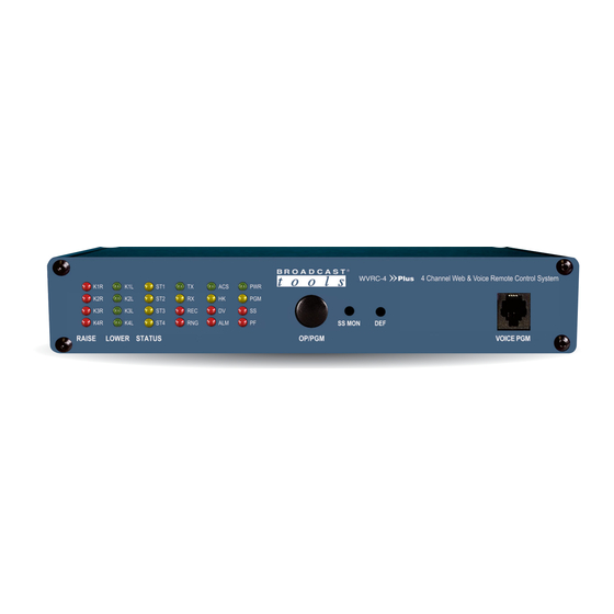
Page 6: Front Panel Indicators And Controls
WVRC-4 Plus Installation and Operation Manual Front panel indicators and controls Name Type Description K1–K4 Raise Illuminates when corresponding raise relay isactivated. K –K4 Lower LED Illuminates when corresponding lower relay is activated. ST1 – ST4 Illuminates when corresponding status input is activated. -
Page 7: Rear Panel Connections
WVRC-4 Plus Installation and Operation Manual Rear panel connections Name Type Description CHS GND #6 screw Chassis ground screw. Tie to station ground system. 2.1mm Jack Power Failure power jack (optically-isolated). 6 - 12 VDC, center positive. SS-LT/SS-RT Connector Unbalanced silence sensor audio input left/right, ground. -
Page 8: Connecting Your Wvrc-4 Plus To External Equipment
Permanent damage may occur to the WVRC-4 Plus and/or external equipment if a high voltage source is connected to the WVRC-4 Plus! Failure to observe this warning may also cause injury to the installer or other personnel. CAUTION! DO NOT CONNECT SAMPLE VOLT- AGES IN EXCESS OF POSITIVE 10 Volts DC OR DAMAGE MAY OCCUR TO YOUR WVRC-4 Plus. -
Page 9: Status/Logic Inputs
CAUTION! Floating Grounds Except for the status/logic (wet) inputs, none of the WVRC-4 Plus’s metering (ana- log) inputs will accept a floating ground. Damage to the WVRC-4 Plus or your equipment may result from connecting a floating ground output to the WVRC-4 Plus. -
Page 10: Control Relays
“TEMP” -67°F to +257°F (-55°C TO +125°C). NOTE: The tempera- ture probe should only be installed or removed with the power supply disconnected from the WVRC-4 Plus. Please contact the factory for the proper extension cable. Please limit the total length of cable to 50 feet. -
Page 11: Web Setup/Operation
CAUTION! NEVER DOWNLOAD FIRMWARE UPDATES OR CHANGES TO THE XPORT WEBSERVER UNLESS INSTRUCTED TO DO SO BY BROADCAST TOOLS®. DOING SO DELETES ALL SOFTWARE AND VOIDS ALL WARRANTIES FROM BROADCAST TOOLS®, INC. NOTE: We recommend the use of the latest version of Firefox, Safari or Chrome as your browser. - Page 12 WVRC-4 Plus Installation and Operation Manual Step 1: Open the control panel by clicking on the start menu, click on settings, then click on Control Panel. (Note that the control panel shown is in “Classic View”. If con- trol panel is in “Category View” select the “Classic View” option before proceeding.) Step 2: Double click on the icon labeled Network Connections.
- Page 13 WVRC-4 Plus Installation and Operation Manual Step 3: Right click on the icon labeled Local Area Connection. Another menu will appear. Select the option at the bottom of the menu labeled Properties. The Local Area Connection Properties window will appear.
-
Page 14: Opening The Login Web Page
WVRC-4 Plus Installation and Operation Manual Opening the LOGIN Web Page Connect the supplied GRAY colored XOVER cable between the PC’s Ethernet port and the products “NET” network RJ45 jack. Connect the supplied 12 volt DC only, 2.5 amp power supply to the product’s power jack labeled 12V DC Power. -
Page 15: Login" Web Page
WVRC-4 Plus Installation and Operation Manual “Login” Web Page The Login screen displays the Username and Password entry points as well as the date, time, and site ID. You may view the password by checking the “Show Password” box. After you have successfully logged in, the Monitor/Control page will be displayed. -
Page 16: Monitor/Control" Web Page
WVRC-4 Plus Installation and Operation Manual “Monitor/Control” Web Page The Monitor/Control page allows the monitoring and/or control of the WVRC-4 Plus. The following is an explanation of each item on this page: Queued Logs: Displays the number of queued log entries scheduled to be emailed. -
Page 17: User Setup" Web Page
WVRC-4 Plus Installation and Operation Manual “User Setup” Web Page Eight Usernames and Passwords may be configured for up to three access levels: “admin” allows complete configuration access and control. “Monitor/Control” allows the following access: About, Monitor/Control, Show log, Help, and Logout. -
Page 18: I/O Setup" Web Page
The WVRC-4 offers two forms of logging. The first is the snapshot email log which compiles snapshots of all inputs and outputs with logging enabled at a user defined interval. For example, the WVRC-4 Plus can be configured to record a snapshot of a metering input each hour and then email those compiled readings every 24 hours. -
Page 19: Metering" Setup Page
WVRC-4 Plus Installation and Operation Manual “I/O” Setup Page Metering Metering input selection: Select metering inputs 1 - 4 for configuration. Meter Label: Used to identify the metering input source. Meter Units: Units label in engineering units, such as V = Volts, A = Amps, W = Watts, etc. -
Page 20: Temperature" Setup Page
WVRC-4 Plus Installation and Operation Manual “I/O” Setup Page - Temperature Temperature Label: Identifies the temperature input source. Alarms High: This option enables the “High Trip Point” alarm. Alarms Low: This option enables the “Low Trip Point” alarm. Alarms Exit: This option enables the generation of an alarm after exiting an alarm state. -
Page 21: Virtual Channels" Setup Page
WVRC-4 Plus Installation and Operation Manual “I/O” Setup Page - Virtual Channels Virtual Channel selection: Select the virtual channel (1 - 4) for configuration. Virtual Channel Label: Identifies the virtual channel. Virtual Channel Units: Unit label in engineering units, such as V = Volts, A = Amps, W = Watts, etc. -
Page 22: Status" Setup Page
WVRC-4 Plus Installation and Operation Manual “I/O” Setup Page - Status Input Status Messages: Identifies the status input source and condition. Alarms OFF: Enables an alarm when the input is OFF. Alarms ON: Enables an alarm when the input is ON. -
Page 23: Relays" Setup Page
WVRC-4 Plus Installation and Operation Manual “I/O” Setup Page - Relays Relay Label: Used to identify the attached device/function. Alarms OFF: Enables an alarm when the relay is OFF. Alarms ON: Enables an alarm when the relay is ON. Email Addresses: This allows you to assign up to 8 email addresses to receive alarm emails. - Page 24 WVRC-4 Plus Installation and Operation Manual “I/O” Setup Page - Relays - Event Action Sequencer Event action sequencer: Allows an alarm event from one of the inputs to automat- ically trigger the relay. Enable: Enables the event action sequencer. Action:...
-
Page 25: Silence Sensor" Setup Page
WVRC-4 Plus Installation and Operation Manual “I/O” Setup Page - Silence Sensor Label: Used to identify the audio source. Alarms Enter: Enables an alarm for when silence is detected. Alarms Exit: Enables an alarm for when the silence detector detects that audio has returned. -
Page 26: Power Failure" Setup Page
WVRC-4 Plus Installation and Operation Manual “I/O” Setup Page - Power Failure Label: Used to identify the input. Alarms Enter: This option enables an alarm if voltage is no longer present on the PF input. Alarms Exit: This option enables an alarm when voltage returns to the PF input. -
Page 27: Chassis Temperature" Setup Page
WVRC-4 Plus Installation and Operation Manual “I/O” Setup Page - Chassis Temperature (WVRC-4 rev. K and above) Alarms Enter: This option enables the “Temp High” alarm. Alarms Exit: This option enables the generation of an alarm after exiting an alarm state. -
Page 28: Internet Down" Setup Page
WVRC-4 Plus Installation and Operation Manual “I/O” Setup Page - Internet Down The Internet Down alarm allows the WVRC-4 Plus to monitor the reachability of a specified DNS address or IP address using an ICMP ping. The ICMP ping is a commonly used extension to the Internet Protocol (IP). -
Page 29: Dial Settings" Setup Page
Status Input 1 the WVRC-4 will call dial out number 1 (3608549559) if no acknowledgement is received it will then call dial out number 2 (8772505575). The WVRC-4 Plus can be also be configured to dial a pager when an alarm is trig- gered. - Page 30 Security access code has been entered. The default code is 456. Lap: Specifies the number of times the WVRC-4 Plus will go through all of the numbers in the dial list when calling out an alarm if it does not receive an acknowledgement.
-
Page 31: Scheduler" Setup Page
WVRC-4 Plus until the save button is pressed. NOTE: The Scheduler page does not auto refresh, please click “refresh” to update the “Next Event”... - Page 32 The Pulse duration is configured on the "Relay Setup Page" under "I/O Setup". Adjust Time: To assist with daylight savings adjustment, the WVRC-4 Plus can add or subtract 1 hour from the time-zone offset. Time-zone offset is initially configured under "Email/Network Setup"...
- Page 33 WVRC-4 Plus Installation and Operation Manual “Scheduler” Setup Page – Actions – cont Execute Macro: The Scheduler can also execute either the true or false clause of any macro defined under the "Macros" Setup page. Select "Execute Macro" from the "Event"...
- Page 34 WVRC-4 Plus Installation and Operation Manual “Scheduler” Setup Page – Actions – cont To select the Date for an "Exact Date" type choose the month and day from the two drop down boxes under "Date" To select the date for a "Day/Months" type choose the months and days of the week by checking the checkboxes under "Date"...
-
Page 35: Macros" Setup Page
WVRC-4 Plus Installation and Operation Manual “Macros” Setup Page The WVRC-4 Plus's macro system allows for the ability to trigger relay events based on combinatorial logic of status and meter inputs. Each of the 50 available macro slots has a conditional statement as well as a true and false clause. When a macro is enabled it is evaluated every second and either the true or false clause is execut- ed, empty true and false clauses are allowed and no action is taken if they are empty. - Page 36 WVRC-4 Plus Installation and Operation Manual Conditional: Conditional statements must be encompassed in open and closed parenthesis and additional parenthesis are allowed within the statement in order to enforce evalua- tion order. Conditionals must be separated by the & or the | symbols to indicate Boolean AND and Boolean OR operations.
- Page 37 WVRC-4 Plus Installation and Operation Manual The first will evaluate as TRUE if Boolean 1 is TRUE and will evaluate as FALSE if Boolean 1 is FALSE. The second will evaluate as TRUE if Boolean 2 is FALSE and will evaluate as FALSE if Boolean 2 is TRUE.
-
Page 38: Restoring To Factory Defaults
WVRC-4 Plus Installation and Operation Manual Restoring to Factory Defaults NOTE: The WVRC-4 Plus factory defaults may be restored by holding the front panel “PGM” button IN, repowering the unit, wait for the SS and PF LED’s to flash, then release the “PGM” button. -
Page 39: Email/Network Setup" Web Page
WVRC-4 Plus Installation and Operation Manual “Email/Network Setup” Web Page SET UP e-mail: voice: fax: support@broadcasttools.com 360.854.9559 866.783.1742... - Page 40 WVRC-4 Plus Installation and Operation Manual “Email/Network Setup” Web Page – Device Network Settings - cont Device Address: Enter a static IP address here. Default: 192.168.1.55 Device Netmask: Enter the Netmask here: Default: 255.255.255.0 Gateway Address: Enter the Gateway IP here: Default: 192.168.1.1...
- Page 41 WVRC-4 Plus Installation and Operation Manual “Email/Network Setup” Web Page – Email Logging Settings - cont Logging Email Address: Email address for the “Logging” email recipient (may be different from the 8 “Alarm” Recipient Addresses. Logging emails and Daily emails are sent to this address.
- Page 42 WVRC-4 Plus Installation and Operation Manual “Email/Network Setup” Web Page – NTP Settings NTP (Time) Server Address: Enter the NTP address here. Default: pool.ntp.org NTP Port: Normally 123. Default: 123 NTP Update Interval (Min): Interval between timing updates. Default: 30 NTP Enabled: Must be enabled to sync .
- Page 43 WVRC-4 Plus Installation and Operation Manual “Email/Network Setup” Web Page – Controls Save Settings: After pressing the “Save Settings” button, the device will reboot (If you changed the IP address, you must navigate your web browser to the new IP address (if the HTTP port was changed from port 80, be sure to add the new port number after the IP: xxx.xxx.xxx.xxx:port #).
-
Page 44: Show Alarms" Web Page
WVRC-4 Plus Installation and Operation Manual “Show Alarms” Web Page This page displays current alarms. Device : Displays which device and/or devices triggered the alarm. Enter/Exit: Displays if the alarm is entering or exiting an alarm condition. Date: Displays what date the alarm was logged. -
Page 45: About" Web Page
WVRC-4 Plus Installation and Operation Manual “About” Web Page The “About” Web Page displays the product name, firmware version numbers, and Broadcast Tools® Web site link. WEBSITE: Visit our web site for product updates and additional information. SET UP e-mail:... -
Page 46: Dial-Up Operation
When the WVRC-4 Plus dials-out to notify the user of an alarm event it will speak the greeting message followed by the alarm message and security access code prompt. - Page 47 WVRC-4 Plus Installation and Operation Manual Using the Dial-Up Interface - cont. Alarm Enable Registers All of the alarm call-outs can be enabled, disabled or polled remotely using DTMF control. The status alarms can be controlled by entering 97 followed by the status number 1 through 4 and 1 for enable, 0 of disable or 9 for poll.
-
Page 48: Recording Voice Messages
1 - Connect a touch-tone telephone to either the front or rear panel RJ-11 jacks labeled “PGM”. 2 - Put the WVRC-4 Plus in to programming mode by pressing the front panel “PGM” button; this should illuminate the front panel “PGM” LED. - Page 49 WVRC-4 Plus Installation and Operation Manual Message Address Seconds Greeting Alarm Normal Raise Lower Access Accepted Silence Alarm Power Fail Alarm High Status Input 1 Status Input 2 Status Input 3 Status Input 4 Analog Input 1 Analog Input 2...
-
Page 50: Configure Dip Switch Settings
WVRC-4 Plus Installation and Operation Manual CONFIGURE DIP Switch settings: NOTE: The “UP” position is OFF DIP 1 - Unused DIP 2 - OFF = Voice Temperature in Fahrenheit, ON = Celsius. DIP 3 - If OFF, description messages will be played when controlled via dial-up. -
Page 51: Specifications
WVRC-4 Plus Installation and Operation Manual Specifications Ethernet Interface: RJ-45, 10Base-T or 100Base-TX, auto sensing with Link & activity indicator - Full/half duplex. Control Logic: Micro with non-volatile memory and web server. Temperature Sensor input: Probe (1 supplied) with 25-foot cable and 1/8” T/R/S plug. -67°F to +257°F (-55°C TO +125°C). -
Page 52: Warranty
If Broadcast Tools is notified, in writing, of a failure of any item manufactured by Broadcast Tools to conform to the foregoing Limited Warranty within one (1) year following the date of the Buyer’s acquisition of the item, and if the item is returned to Broadcast Tools in accordance with Broadcast Tools’... -
Page 53: Declaration Of Conformity
WVRC-4 Plus Installation and Operation Manual Declaration of Conformity The XPORT Device contained in the WVRC-4 Plus conforms to the following standards: (according to ISO/IEC Guide 22 and EN 45014) Manufacturer’s Name & Address: WVRC-4 Plus: Broadcast Tools, Inc. 131 State Street. - Page 54 Product_Name Installation and Operation Manual APPENDIX e-mail: voice: fax: support@broadcasttools.com 360.854.9559 866.783.1742...
- Page 55 Product_Name Installation and Operation Manual APPENDIX e-mail: voice: fax: support@broadcasttools.com 360.854.9559 866.783.1742...
- Page 56 Product_Name Installation and Operation Manual APPENDIX e-mail: voice: fax: support@broadcasttools.com 360.854.9559 866.783.1742...
- Page 57 Product_Name Installation and Operation Manual APPENDIX e-mail: voice: fax: support@broadcasttools.com 360.854.9559 866.783.1742...
Need help?
Do you have a question about the WVRC-4 Plus and is the answer not in the manual?
Questions and answers