Table of Contents
Advertisement
Available languages
Available languages
Advertisement
Table of Contents

Related Manuals for NAMCO 90500146

Summary of Contents for NAMCO 90500146
-
Page 1: Operators Manual
TIME CRISIS III OPERATORS MANUAL T IS THE RESPONSIBILITY OF THE OPERATOR TO MAINTAIN CUSTOMER SAFETY AT ALL TIMES AND IT IS IMPERATIVE THAT THE DETAILS SET OUT IN THIS MANUAL ARE FOLLOWED PRECISELY Issue 1 Part No. 90500146... - Page 2 Page 2...
- Page 3 is a copyrighted anti-copying technology created by Sony Corp. This mark does not necessarily imply compatibility with other products bearing the “MAGICGATE” trademark. is a trademark of Sony Corporation. The CD-ROM supplied with the machine must not be copied, modified, publicly distributed, or used for purposes other than operation of the machine.
-
Page 4: Table Of Contents
Contents OPERATORS MANUAL ..........................1 GENERAL SAFETY CONSIDERATIONS ....................6 ALLGEMEINE SICHERHEITSHINWEISE ....................8 GENERELLE SIKKERHEDSOVERVEJELSER ..................10 CONSIDERACIONES GENERALES DE SEGURIDAD................12 CONSIGNES GENERALES DE SECURITE .................... 14 Ε ΕΤΑΣΗ ΓΕΝΙΚΗΣ ΑΣΦΑΛΕΙΑΣ ......................16 CONSIDERAZIONI GENERALI SULLA SICUREZZA ................18 VANLIGE SIKKERHETSTILTAK ....................... - Page 5 6. MAINTENANCE ..........................57 Replacing the Pedal Switch ....................... 59 Greasing the Pedal Assy Plunger ....................60 Replacing the Pedal Plunger ...................... 61 Removing the Play Panel ......................62 Gun Assembly ........................... 63 6-5-1 Removing the Gun Assembly ....................63 6-5-2 Removing the Gun Slides ....................
-
Page 6: General Safety Considerations
No part of this publication may be reproduced by any mechanical, photographic or electronic process, or in the form of phonographic recording, nor may it be stored in a retrieval system, transmitted or otherwise copied for private use, without permission from NAMCO EUROPE LIMITED. While the information contained in this manual is given in good faith and was accurate at the time of printing, NAMCO EUROPE LIMITED reserve the right to make changes and alterations without notice. - Page 7 NOTES ON INSTALLATION NEVER turn the power to the machine ON until installation has been completed. In order to prevent possible electric shocks, be sure that the equipment is connected to the mains with a securely connected earthed plug. So that customers are not injured by the movement of the equipment, ensure that there is at least 500mm seperation between other equipment or walls.
-
Page 8: Allgemeine Sicherheitshinweise
Dieses Dokument darf in keiner Weise vervielfältigt werden. Jegliche Tonaufnahmen sowie die Speicherung auf Datenträger (Suchsysteme), die Weitergabe oder sonstiges Kopieren für den gewerblichen und privaten Gebrauch sind untersagt und bedürfen der vorherigen Genehmigung durch NAMCO EUROPE LIMITED. Die informationen in diesem Handbuch entsprechen den Tatsachen bei Drucklegung. NAMCO EUROPE LIMITED behält sich jedoch das Recht zu Änderungen ohne vorherige Bekanntgabe vor. - Page 9 HINWEISE ZUR AUFSTELLUNG NIEMALS das Gerät einschalten bevor die Aufstellung völlig abgeschlossen ist. Zur Vermeidung von Elektroschlägen muß das Gerät mit einem ordnungsgemäß geerdetem Netzstecker an die Stromversorgung angeschlossen werden. Um zu vermeiden, daß Kunden durch die Gerätebewegungen verletzt werden, muß ein Sicherheitsabstand zu anderen Geräten und Wänden von mindestens 50cm eingehalten werden.
-
Page 10: Generelle Sikkerhedsovervejelser
Denne udgivelse må ikke reproduceres af nogen som helst mekanisk, fotografisk eller elektrornisk proces eller i form af indspilning, den må heller ikke lagres i et eftersøgningssystem transmitteres eller kopieres til nogen form for offentlig benyttelse uden tilladelse fra Namco Europe Limited. Da informationerne i denne manual er givet med god tro og var korrekt på... - Page 11 PUNKTER OM INSTALLATION Tænd aldrig for strømmen til maskinen før installering er fuldført. For at undgå mulige elektriske stød sikres, at maskinen er forbundet til hovedstrømmen med sikkert monterede jordstik. For at kunder ikke kommer til skade ved spillets bevægelser sikres, at der er mindst 50cm afstand til andre maskiner og vægge.
-
Page 12: Consideraciones Generales De Seguridad
No se permite la reproducción total ni parcial de esta publicación por ningún medio mecánico, fotográfico o electrónico, grabaciones fonográficas, ni su almacenamiento informático, su transmisión o su copia, ya sea para uso público o privado, sin permiso de NAMCO EUROPE LIMITED. Si bien la información contenida en este manual se da de buena fe y es correcta en el momento de su impresión, NAMCO EUROPE LIMITED se reserva el derecho de hacer cambios y alteraciones sin previo aviso. - Page 13 NOTAS DE INSTALACIÓN. JAMÁS ENCIENDA la máquina antes de haber completado la instalación. Para evitar posibles descargas eléctricas, asegúrese de que la máquina está conectada a la red con un enchufe provisto de toma de tierra. Para que los usuarios no sufran lesiones debido al movimiento del juego, asegúrese de que hay al menos 500 mm de separación entre éste y otras máquinas o las paredes.
-
Page 14: Consignes Generales De Securite
Aucun élément de cette publication ne sera reproduit, ni par procédé mécanique, photographique ou électronique, ni par un moyen d’enregistement phonographique. Ces informations ne seront ni stockées grâce à un procédé de récupération, ni transmises ou autrement copiées pour un usage publique ou privé, sans l’autorisation de NAMCO EUROPE LIMITED. Malgré... - Page 15 NOTES D’INSTALLATION NE JAMAIS mettre le jeu en marche avant que l’installation ne soit complétement effectuée. Afin de prévenir une éventuelle électrocution, s’assurer que la machine est connectée au réseau avec une prise de terre reliée selon les normes de sécurité. Afin que les clients ne soient pas blessés par les mouvements du jeu, s’assurer qu’il existe au moins 500 mm de séparation aves les autres jeux ou les murs.
-
Page 16: Ε Εταση Γενικησ Ασφαλειασ
Κανένα μέρ ς αυτής της έκδ σης δεν μπ ρεί να αναπαρα θεί με π ι δήπ τε μη ανικ ,φωτ γραφικ ή ηλεκτρ νικ μέσ , ή με μ ρφή φωνητικής η γράφησης και ύτε να απ θηκευτεί με επαν ρθωτικ σύστημα , να μεταδ θεί ή να αντιγραφεί για δημ σια ή ιδιωτική ρήση , ωρίς... - Page 17 ΣΗΜΕΙΩΣΕΙΣ ΓΙΑ ΤΗΝ ΕΓΚΑΤΑΣΤΑΣΗ Π ΤΕ να μην ανά ει τ μη άνημα εάν δεν έ ει λ κληρωθεί η εγκατάσταση. Για την απ φυγή ηλεκτρικών σ κ πρέπει τ μη άνημα να έ ει γειωθεί. Για την απ φυγή κινδύν υ σε κάπ ι ν παίκτη , πρέπει τ μη άνημα να έ...
-
Page 18: Considerazioni Generali Sulla Sicurezza
Nessuna parte di questa pubblicazione può essere riprodotta con processo meccanico, fotografico o lettronico, nè sotto forma di registrazione fonografica, nò può essere memorizzata in un sistema di salvataggio, trasmessa o in altro modo copiata per uso pubblico o privato, senza l’autorizzazione di NAMCO EUROPE LIMITED. Le informazioni contnute in questo manuale sono state date in buona fede ed erano accurate al momento della pubblicazione. - Page 19 NOTES D’INSTALLATION NON ACCENDERE MAI la macchina finchè l’installazione non è stata completata. Allo scopo di prevenire possibili scosse elettriche, la macchina deve essere obbligatoriamente collegata alla rete con un connettore messo a terra con connessioni sicure. Perchè i clienti non siano feriti dal movimento del gioco, assicurarsi che ci siano almeno 500mm di distanza rispetto alle altre macchine o rispetto al muro.
-
Page 20: Vanlige Sikkerhetstiltak
Ingen del av denne utgivelsen må reproduseres av noen mekaniske, fotografiske elle elektroniske prosesser, eller i form av fotografiske opptak, og ikke kan det lagres i et gjenvinnbart system, sendt eler kopiert for offentlig eller privat bruk, uten tillatelse fra NAMCO EUROPE LIMITED. - Page 21 MERKNADER VED INSTALLASJON Slå ALDRI på maskinens strømforsyning før installasjonen er fullført. For å forhindre eventuelle elektriske sjokk, forsikre deg om at maskinen er koplet til et strømnett med ordentlig jording. For å forhindre at kundene blir skadet av spillets bevegelige deler. forsikre deg om at det er minst 500mm avstand mellom andre maskiner eller vegger.
-
Page 22: Algemene Veiligheidsoverwegingen
Niets uit deze publikatie mag worden gereproduceerd door enig mechanisch, fotografisch of electronisch proces, of in de vorm van een fonografische opname, noch mag het opgeslagen worden in een retrieval systeem, doorgezonden of anderszins gekopieerd voor publiek of privégebruik, zonder toestemming van Namco Europe Limited. Ofschoon de informatie in deze handleiding in goed vertrouwen is gegeven en nauwkeurig was ten tijde van het drukken, houdt Namco zich het recht voor om veranderingen en aanpassingen te maken zonder bericht. - Page 23 Opmerkingen aangaande Installatie Sluit de machine nooit aan op de stroomtoevoer totdat de installatie is voltooid. Om mogelijke electrische schokken te voorkomen, dient ervoor gezorgd te worden dat de machine middels een goed vastzittende aardstekker op het lichtnet is aangesloten. Om ervoor te zorgen dat klanten niet gewond raken door de beweging van het spel, dient ervoor gezorgd te worden dat er minimaal 500mm ruimte is tussen andere machines of muren.
-
Page 24: Avisos De Perigo
Nenhuma parte desta publicacão poderá ser reproduzida por processos mecanográficos, fotográficos, electrónicos ou ainda sob a forma de gravacão sonora nem tão pouco poderá ser gravada através de sistemas informáticos transmissiveis ou de outra forma copiados para uso publico ou privado sem autorização expressa da NAMCO EUROPA LIMITADA. A informação contida neste manual foi fornecida de boa fé, sendo rigorosa na altura da sua publicação. - Page 25 NOTAS SOBRE A INSTALAÇÃO NUNCA ligar a maquina sem que a instalação esteja completamente finalizada. Afim de evitar possiveis choques electricos, certifique-se que a maquina está ligada à rede de alimentação com uma ficha protegida com circuito de terra. Afim de evitar ferimentos pessoais nos clientes, provocados pelo movimento da maquina, certifique-se que existe pelo menos 500mm de separação entre outras maquinas ou paredes.
-
Page 26: Allmänna Säkerhetsbeaktanden
Ingen del av denna publikation får reproduceras, varken fotografiskt, elektroniskt eller i någon form av ljudinspelning. Det får inte heller lagras i något återvinningssystem, översändas eller på annat sätt kopieras för offentlig eller privat användning, utan tillstånd från NAMCO EUROPE LIMITED. Eftersom informationen i denna manual lämnas ut i god tro och var korrekt när den trycktes, reserverar sig NAMCO EUROPE LIMITED för ändringar. - Page 27 ATT BEAKTA VID INSTALLATION Sätt aldrig på strömmen på maskinen innan installationen är klar. För att förhindra elektriska chocker, försäkra dig om att maskinen kopplas till strömförsörjning med jordad kontakt För att undvika skador av spelets rörelser, försäkra dig om att det finns ett avstånd på...
-
Page 28: Yleiset Turvallisuunäkökodat
Tästä julkaisusta ei saa ottaa missään muodossa kopioita yksityis- tai julkiseen käyttöön ilman NAMCO EUROPE LIMITED:in lupaa. Tässä ohjekirjassa olevat tiedot pitävät julkaisuhetkellä paikkansa. NAMCO EUROPE LIMITED:illä on kuitenkin oikeus muutoksiin ilman erillistä ilmoitusta. Tämä laite on valmistettu EC direktiivien mukaisesti. Se on testattu ja todettu noudattavan seuraavia direktiivejä: 89/336/EEC ja 72/23/EEC (EN55014-1, EN55014-2 ja EN 60335-2-82 standardit). - Page 29 ASENNUSHUOMIOITA Älä koskaan kytke laitetta päälle ennen kuin asennus on suoritettu loppuun. Tämän laitteen virtalähde on kytkettävä maadoitetulla johdolla maadoitettuun pistorasiaan, jotta sähköiskun vaaraa ei olisi. Varmista, että laitteen ja seinän tai toisen laitteen välissä on vähintään 500 mm, jotta asiakkaat eivät loukkaannu laitteen likkumisesta johtuen.
-
Page 30: Specifications
1. SPECIFICATIONS POWER SUPPLY:- 230v / 370watts AC AMBIENT OPERATING +5°C to +25°C TEMPERATURE MONITOR:- Mitsubishi VS-50609 Projection COIN ACCEPTOR:- Mars CashFlow - 4 Channel Dispense DIMENSIONS:- Assembled 2330(w) x1790(d) x 2320(h) Monitor Cabinet 1160(w) x 760(d) x 1890(h) Coin Tower Assy 1540(w) x 540(d) x 1155(h) Header Assy... -
Page 31: Main Components
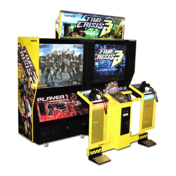
2. MAIN COMPONENTS Page 31... -
Page 32: How To Play
3. HOW TO PLAY This is a gun shooting game where players press on a foot pedal to hide behind an object to avoid an enemy attack, then release the pedal to get out from behind the object and attack the enemy. HOW TO CONTROL 1. -
Page 33: Installation
4. INSTALLATION This machine is designed for INDOOR USE ONLY. Do not install in the following places. Outdoors Direct Sunlight, places with excessive humidity or dust, places where there is water leakage, near air-conditioning or heating equipment, places with excessive heat or cold temperature. Places where it would be in the way of emergency exits or fire extinguishing equipment. - Page 34 CETTE MACHINE EST DESTINEE UNIQUEMENT A UN USAGE INTERIEUR NE PAS INSTALLER LA MACHINE DANS LES ENDROITS SUIVANTS A l’extérieur. Directement exposée au soleil, aux endroits excessivement humides ou poussiéreux, aux endroits où il y a des risques de fuite d’eau, près de ventilateurs ou source de chaleur, aux endroits très chauds ou froids.
- Page 35 DEZE MACHINE IS ALLEEN VOOR GEBRUIK BINNENSHUIS ONTWORPEN INSTALLEER DE MACHINE NIET OP DE VOLGENDE PLAATSEN Buiten In direct zonlicht, op plaatsen met een zeer hoge vochtigheidsgraad of met veel stof, op plaatsen waar een waterlek is, dichtbij airco’s of verwarmingsapparatuur, op plaatsen met een zeer hoge of koude temperatuur.
-
Page 36: Notes On Installation
Notes on Installation WARNING • NEVER turn the power to the machine ON until installation has been completed. WARNING • In order to prevent possible electric shocks, be sure that the machine is connected to the mains with a securely connected earthed plug. -
Page 37: Joining The Monitor Cabinets
Joining the Monitor Cabinets Place the two Monitor Cabinets together, and remove the Lower Rear Door on each cabinet. Fit the hex head screw (M8x40), wingnut (M8). and flat washers to join the rear of the Monitor Cabinets together. Monitor Cabinet Assy Flat Washer Wing Nut (M8) - Page 38 Remove 4off security screws (M5x12) and remove the Joint Box Cover. Fit the Joint Box to the 4off socket head screws (M8x40) and tighten the screws. Feed the looms from both Monitor Cabinets into the Joint Box, and connect the connectors.
-
Page 39: Fitting The Header Assembly
Fitting the Header Assembly The Header Assembly has a forward centre of gravity, so it is important that at least two people are used to fit or remove the Header Assembly. The fitting position of the Header Assembly is high, and it is important that a means of reaching the height safely, without stretching, is available. -
Page 40: Connecting The Coin Tower Assy To The Monitor Cabinet
Connecting the Coin Tower Assy to the Monitor Cabinet Fit 4off Socket cap screws (M8x16) to retain the Joint Box Assy tot he Coin Tower Assy. Feed the looms from the Giun Tower Assy into the Joint Box, and connect the connectors. -
Page 41: Adjusting The Level Adjusters
Adjusting the Level Adjusters When the game is in it’s final position, lower the six (6) Level adjusters, 4 on the Monitor Cabinet and 2 on the Coin Tower Assy, with a spanner, so that all castors are raised from the floor by approximately 5mm. Tighten the lock nuts with a spanner to ensure that the Level Adjusters do not move. -
Page 42: Fitting The Pedal Assemblies
Fitting the Pedal Assemblies Remove 2off security screw (M5x12) and remove the Joint Bracket from the Pedal Assy. (Take care not to lose the screws as these will be used to fit the Pedal Assy. Pedal Assy Security screw (M5x12) Joint Bracket Fit the Joint bracket to the Coin Tower Assy, finger tight only, with the 2off security screw (M5x12) -
Page 43: Fitting The Dvd-Rom
Fitting the DVD-ROM The DVD-ROM must be inserted with the game power ON. To prevent electric shock, accident or injury, do not touch any parts other than those specified below. Remove the rear panel from the Monitor Cabinet. Pull the actuating button of the Interlock Switch to turn the game ON. Press the Eject button of the DVD-ROM drive to eject the tray. -
Page 44: Adjustments
5. ADJUSTMENTS Adjustment or maintenance on this machine should be carried out by qualified personnel only. Einstellungen und Wartung des Gerätes dürfen nur von dafür qualifiziertem Fachpersonal vorgenommen werden. Justeringer eller vedligehold af denne maskine bør kun udføres af kvalificeret personale. Los ajustes y el mantenimiento de esta máquina deben ser realizados sólo por personal cualificado. -
Page 45: Adjustment Switches
Adjustment Switches The Adjustment switches are located inside the coin door. Service Switch. Press this switch to obtain game credits without incrementing the play meter. Test Switch Slide the test switch ON to enter test mode. Test mode allows testing and the changing of game settings. (Refer to section 5- 2 "Test Mode"... -
Page 46: Test Mode
Test Mode Open the coin door and slide the test switch “ON”. The “Menu Screen” will be displayed on the monitor. Select the test required by using the select up/down switch. The colour of the selected test will change. Activate the test by pressing the Enter switch. Select “EXIT” in each test to return to the “Menu Screen”. -
Page 47: Coin Options
5-2-1 Coin Options Select “COIN OPTIONS” on the menu screen to set the game cost and related settings. The following screen is displayed. Use the Select Up/Down switch to choose the required item then press the Enter button. Use the Select Up/Down switch to change the setting. Press the Enter button to return to option select mode. -
Page 48: Game Options
5-2-2 Game Options Select “GAME OPTIONS” on the menu screen to set the game variables, the following screen is displayed. Use the Select Up/Down switch to choose the required item then press the Enter button. Use the Select Up/Down switch to change the setting. Press the Enter button to return to option select mode. -
Page 49: I/O Test
5-2-3 I/O Test Select “I/O TEST” on the menu screen to test the I/O PCB, initialize the gun accuracy and to test switches and gun solenoids, the following screen is displayed. Use the Select Up/Down switch to choose the required item then press the Enter button. -
Page 50: I/O Pcb Check
5-2-3-1 I/O PCB Check Select “I/O PCB CHECK” on the I/O TEST menu screen, the following screen is displayed. I/O TEST : 1234 [ON:RED] LINK : ON 2 LINK AS (LEFT) I/O PCB CHECK : Connect OK namco ltd. : TSS-I/O; ver2.11; GUN EXTENSION EXIT SELECT SW : CHOOSE ENTER SW : ENTER... - Page 51 To check the gun accuracy shoot the gun at the screen. The screen will display the position of the bullet impact. Check the the displayed impact is at the aimed for position. If the displayed impact is incorrect press the Service Switch or press the Foot Pedal, the following screen will be displayed.
-
Page 52: Switch Test
5-2-3-3 Switch Test Select “SWITCH TEST” on the I/O TEST menu screen, the following screen is displayed. I/O TEST : 1234 [ON:RED] LINK : ON 2 LINK AS (LEFT) SWITCH TEST I/O PCB CHECK SERVICE TEST UP SELECT DOWN SELECT ENTER GUN TRIGGER FOOT PEDAL... -
Page 53: Solenoid Test
5-2-3-4 Solenoid Test Select “SOLENOID TEST” on the I/O TEST menu screen, the following screen is displayed. I/O TEST : 1234 [ON:RED] LINK : ON 2 LINK AS (LEFT) SOLENOID TEST PULL GUN TRIGGER TO ACTION EXIT SELECT SW : CHOOSE ENTER SW : ENTER The gun solenoid will operate each time the gun trigger is pulled. -
Page 54: Monitor Test
5-2-4 Monitor Test Select “MONITOR TEST” on the menu screen to make adjustments to the monitor. The following screen is displayed. Use the Select Up/Down switch to choose the required item then press the Enter button. Press the Enter button to return to Monitor Test Screen. Select “EXIT”... -
Page 55: Sound Test
5-2-5 Sound Test Select “SOUND TEST” on the menu screen to test the audio and adjust the volume settings. The following screen is displayed. Use the Select Up/Down switch to choose the required item then press the Enter button. Use the Up/Down switch to change the setting. Press the Enter button to return to item select mode Select “EXIT”... -
Page 56: Ads Data (Bookkeeping)
5-2-6 ADS Data (Bookkeeping) Select “ADS DATA” from the menu screen to view the bookkeeping details. Select “EXIT” and press the enter switch to return to the menu screen. 5-2-7 Others Select “OTHERS” on the menu screen to display the ROM version, to set the on screen language, display mode and to set all settings to factory default. -
Page 57: Maintenance
6. MAINTENANCE Adjustment or maintenance on this machine should be carried out by qualified personnel only. Ensure that the POWER to the machine is turned OFF before commencing any maintenance work. (Trouble shooting, service or repairs etc.) Einstellungen und Wartung des Gerätes dürfen nur von dafür qualifiziertem Fachpersonal vorgenommen werden. - Page 58 Aanpassingen of onderhoud aan deze machine dient alleen uitgevoerd te worden door bekwaam personeel. Zorg ervoor dat de machine UITgeschakeld is voordat er enig onderhoudswerk wordt verricht (troubleshooting, reparaties etc.) Afinações ou manutenção nesta maquina, deverão ser efectuadas sómente por pessoal qualificado. Certifique-se que a maquina se encontra desligada sempre que iniciar qualquer tipo de trabalho de manutenção.
-
Page 59: Replacing The Pedal Switch
Replacing the Pedal Switch Remove 4off security screw (M5x12) and remove the switch cover plate. urity screw (M5x12) Switch plate Remove 2off pozi head screw (M3x16) and remove the switch. When replacing the switch, ensure that the wires are fitted to the correct terminals. -
Page 60: Greasing The Pedal Assy Plunger
Greasing the Pedal Assy Plunger Remove 4off security screw (M5x12) and remove the switch cover plate. urity screw (M5x12) Switch plate Remove 2off whizztite nuts (M4) and remove the switch. Remove 4off whizztite nuts (M4) and remove the plunger assembly. Note: The plunger is spring loaded. -
Page 61: Replacing The Pedal Plunger
Replacing the Pedal Plunger Remove the plunger assembly. (See 6-2 page 60) Pull the plunger out of the holder. Replace with the new plunger. (The new plunger should have grease applied all over prior to fitting). Holder Plunger Wipe off any old grease and dirt from the pedal plate and regrease. (see 6-2 page 60) Reassemble in reverse order. -
Page 62: Removing The Play Panel
Removing the Play Panel Remove 6off security screw (M5x12). Lift the play Panel slightly and disconnect the connector. Security screw (M5x12) Play panel Connector Security screw (M5x12) Remove the play Panel complete with Gun Assy. Reassemble in reverse order. Page 62... -
Page 63: Gun Assembly
Gun Assembly 6-5-1 Removing the Gun Assembly Remove the Play Panel Assy. (see 6-4 page 62) Remove 2off Whizz nut (M6) and remove the Gun assy from the Play Panel Play panel Connector Whizz nut (M6) Note: When replacing the gun assembly ensure that the earth wires are located on the studs before fitting and tightening the whizz nuts. -
Page 64: Removing The Gun Slides
6-5-2 Removing the Gun Slides Remove the Gun Assy. (see 6-5-1 page 63) With the left side of the gun placed down, remove 4off socket cap screws (M3x10) and 1off button head screw (M4x25) and nut (M4) Nut (M4) Socket cap screw (M3x10) Gun slide L Button head screw (M4x25) -
Page 65: Removing The Gun Covers
6-5-3 Removing the Gun Covers Remove the Gun Slides. (see 6-5-2 page 64) With the left side of the gun placed down, remove 4off button head screw (M4x10), 1off button head screw (M4x25) and 1off socket cap screw (M3x10), taking care not to lose any of the nuts. Nut (M4) Button head screw (M4x20) -
Page 66: Replacing The Solenoid
6-5-4 Replacing the Solenoid Remove the Gun Covers. (see 6-5-3 page 65) Disconnect the Solenoid Connector. Remove 1off flange screw (M3x10) and remove the Solenoid Bracket. Remove 1off flange screw (M3x8) and detach the earth wire. Loosen the nut (16mm) and pull out the Solenoid. Remove 2off flange screws (M4x6) and detach the Slide Guide. -
Page 67: Replacing The Trigger Switch
6-5-5 Replacing the Trigger Switch Remove the Gun Covers. (see 6-5-3 page 65) Remove the Fast-On terminals from the Microswitch. Remove the Microswitch. Microswitch Fast-On terminals Reassemble in reverse order. Page 67... -
Page 68: Replacing The Flexible Gun Conduit
6-5-6 Replacing the Flexible Gun Conduit Remove the Gun Assy. (see 6-5-1 page 63) Remove 2off security screw (M4x10) and remove the Connector Cover. Remove the Gun Covers (see 6-5-3 page 65) Detach the Solenoid Bracket, Solenoid Connectors and earth wire. Disconnect the PCB connectors and detach the Fast-On connectors from the microswitch. -
Page 69: Replacing The Neon Tubes
Replacing the Neon Tubes The Neon Tubes use high voltage. The game must be turned OFF and disconnected from the power before touching any Neon Parts Remove the Play Panel. (See 6-4 page 62) Remove 6off security screw (M5x12) and remove the Front Grille. Front Grille Security screw (M5x12) - Page 70 Remove 2off hex head screw (M5x20) and remove the Rear Cover. Hex head screw (M5x20) Hex head screw (M5x20) Rear Cover Disconnect the connector from the Neon PCB. Connector Neon PCB Page 70...
- Page 71 Remove the Neon Tube. Note: Always grip the tube by the end caps, not the glass tube. Neon Tube Reassemble in reverse order. Page 71...
-
Page 72: Replacing The Header Tube And Starter
Replacing the Header Tube and Starter Remove 10off security screws (M5x12), and remove the Header Acrylic. Security screw (M5x12) Header Acrylic Starter Fluorescent Tube (40w) Replace the Fluorescent Tube or Starter. Note: The fluorescent tube is fitted with a blue filter. Remove the filter and fit to the new fluorescent tube before refitting the tube to the Header Assy. - Page 73 Page 73...
-
Page 74: Parts
7. PARTS Projector Cabinet - Rear Page 74... - Page 75 i f i t μ i f i l Page 75...
-
Page 76: Projector Cabinet - Front
Projector Cabinet - Front Page 76... - Page 77 s t i e l l ½ " Page 77...
-
Page 78: Coin Tower Assy
Coin Tower Assy a l i Page 78... -
Page 79: Gun Tower Assy
Gun Tower Assy ) t f t s l t s l t s l v i t y t i " 2 " 2 " 2 Page 79... -
Page 80: Gun Assembly
Gun Assembly Page 80... - Page 81 d i l d i l d i l d i l d i l l i a p i l d i l d i l d i l d i l d i l c t i e l i Page 81...
-
Page 82: Pedal Assembly
Pedal Assembly c t i Page 82... -
Page 83: Joint Box
Joint box Page 83... -
Page 84: Service Bracket Assy
Service Bracket Assy d i l c t i c t i c t i Page 84... -
Page 85: Header Assembly
Header Assembly c i l t l i Page 85... -
Page 86: Mains-In Assy
7-10 Mains-In Assy t l i c t i c t i c t i Page 86... -
Page 87: Schematic
8. SCHEMATIC 8.1 PROJECTOR CABINET pBASS AMP PCB Assy (L) SPF (L) SOUND AMP MINI 6w L IN White/Purple SP_OUT1+ Purple SP_OUT1- SOUND L White/Blue SP_OUT2+ SOUND Blue CABINET SP_OUT2- R IN Grey/Green SP_OUT3+ SPEAKERS SOUND R Green SP_OUT3- AMP MINI 2w pBASS AMP PCB Assy (R) +12v SPF (R) - Page 88 8.2 COIN / GUN CABINET SOLENOID ASSY YELLOW YELLOW 12v 2.2w PLAYER 2 WHITE/RED WHITE/RED SSIN1 GUN PCB SSIN1 WHITE/ORANGE WHITE/ORANGE SOL1 SOL1 ASSY WHITE/BLEU WHITE/BLUE TRG1 TRG1 BLACK BLACK YELLOW/BLACK SENSE GUN ASSY BLACK GREEN YELLOW/BRUN VGND SYNC DISPENSE SWITCH VIOLET VIOLET STEP IN...
- Page 89 Copies of Namco Game Manuals can be downloaded from our website: www.namco.co.uk under Components Distribution For all Parts or Technical Support contact: Brent Electronic, Namco House, Units 7-8, Acton Park Estate, The Vale, London. W3 7QE www.brentelectronic.co.uk For Technical Support, Warranty and Advance Replacement Parts:- +44 (0) 20 8324 6120 For Consumable Parts:-...
Need help?
Do you have a question about the 90500146 and is the answer not in the manual?
Questions and answers