Table of Contents
Advertisement
INSTALLATION
INSTRUCTIONS
Ground Water Temperatures 45° - 75°
BMC, Inc.
Bryan, Ohio 43506
WATER SOURCE HEAT PUMP MODELS:
GTB1-A
GTA3600UD1AA
GTA4860UD1AA
GTADP-3642-B
GTADP-3642-C
GTADP-4860-C
GTC36S2-ADCX
GTC48S2-ADCX
GTC60S2-ADCX
GTC36S2-ADNX
GTC48S2-ADNX
GTC60S2-ADNX
Earth Loop Fluid
Temperatures 25° - 110°
Manufactured under the following
U.S. patent number:
8,127,566
Blower Section
Coil Section
Coil Section
Coil Section
Coil Section
Coil Section
Compressor Section
Compressor Section
Compressor Section
Compressor Section
Compressor Section
Compressor Section
MIS-2830
Manual:
Supersedes: 2100-537H
File:
Date:
2100-537
I
Volume I, Tab 8
10-11-12
I
Manual
2100-537
Page
1 of 54
Advertisement
Table of Contents
Troubleshooting

Related Manuals for BMC GTB1-A


Summary of Contents for BMC GTB1-A
-
Page 1: Installation Instructions
WATER SOURCE HEAT PUMP MODELS: GTB1-A Blower Section INSTALLATION GTA3600UD1AA Coil Section INSTRUCTIONS GTA4860UD1AA Coil Section GTADP-3642-B Coil Section GTADP-3642-C Coil Section GTADP-4860-C Coil Section GTC36S2-ADCX Compressor Section GTC48S2-ADCX Compressor Section GTC60S2-ADCX Compressor Section GTC36S2-ADNX Compressor Section GTC48S2-ADNX Compressor Section... -
Page 2: Table Of Contents
GTA****UD1AA Dimensions ......... 7 Figure 15B Desuperheater Dual Tank System ....... 36 Figure 1B GTADP Fossil Fuel ADP Coil Dimensions .... 8 Figure 1C GTB1-A Dimensions ..........9 Figure 16 Thermistor ............37 Figure 1D GTC**S2-D Dimensions ........10 Figure 17 Component Location .......... -
Page 3: Getting Other Informations And Publications
GETTING OTHER INFORMATION AND PUBLICATIONS These publications can help you install the air FOR MORE INFORMATION, CONTACT conditioner or heat pump. You can usually find these THESE PUBLISHERS: at your local library or purchase them directly from the publisher. Be sure to consult current edition of each standard. -
Page 4: General Information Geo-Trio (Gt Series) Water Source Nomenclature
Geo-Trio™ GT Series Geothermal / Water Source Heat Pump Nomenclature “A” Coil Section 3600 Revision Geo-Trio 3600 (3 Ton) A = E Coated Coils 4860 (4 & 5 Ton) Level Option “A” = Coil Section Series Fossil Fuel “A” Coil Section –... -
Page 5: Table 1 Indoor Blower Performance
NOTE: All values can be changed + 10% via the + adjustment dip switches on the tap select control inclusive in the GTB1-A Blower Section (see instructions later in this manual, or on wiring diagram in blower section). TABLE 2 — FLOW RATES FOR VARIOUS FLUIDS... -
Page 6: Table 4 Water Coil Pressure Drop
TABLE 4 WATER COIL PRESSURE DROP Model GTC36S2 GTC48S2 GTC60S2 PSID Ft. Hd. PSID Ft. Hd. PSID Ft. Hd. 0.23 1.15 2.08 2.77 3.23 3.92 5.31 5.31 7.38 4.61 7.15 9.46 5.77 9.46 11.77 7.38 14.07 9.00 16.38 10.84 18.92 12.69 21.69 14.76... -
Page 7: Figure 1A Gta****Ud1Aa Dimensions
Manual 2100-537 Page 7 of 54... -
Page 8: Figure 1B Gtadp Fossil Fuel Adp Coil Dimensions
FIGURE 1B – GTADP****-* FOSSIL FUEL ADP COIL SECTION DIMENSIONS FIGURE 1B - GTADP****-* FOSSIL FUEL ADP COIL SECTION DIMENSIONS GTADP-3642-C DIMENSION GTADP-3642-B GTADP-4860-C "A" 17 5/8" 21 1/8" "B" 25 1/2" 27 1/2" "C" 7 1/4" 6 3/4" "D" 2 1/8"... -
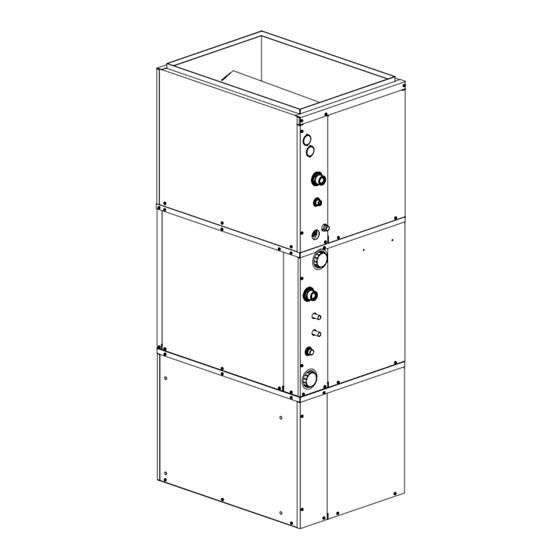
Page 9: Figure 1C Gtb1-A Dimensions
FIGURE 1C – GTB1-A BLOWER SECTION DIMENSIONS 16 3/8" 30" 13 1/4" LOW VOLTAGE ENTRANCE HIGH VOLTAGE K.O. FOR 3 5/8" 22" REMOTE APPLICATIONS ONLY 1 1/4" 24 9/16" 18 13/16" 21" 15 5/8" OPTIONAL SIDE RETURN OPENING ON BOTH SIDES 15"... -
Page 10: Figure 1D Gtc**S2-D Dimensions
Manual 2100-537 Page 10 of 54... -
Page 11: Figure 1E Assembled Upflow/Counterflow App
Manual 2100-537 Page 11 of 54... -
Page 12: Figure 1F Horizontal App. Dimensions
Manual 2100-537 Page 12 of 54... -
Page 13: Figure 2A Upflow & Counterflow Ducting Config
Blower Air Blower Air Manual 2100-537 Page 13 of 54... -
Page 14: Figure 2B Horiz. & Counterflow Ducting Config
Blower Air Blower Air < > Manual 2100-537 Page 14 of 54... -
Page 15: Blower Conversion & Line Power Connect
BLOWER LINE POWER CONNECTION BLOWER CONVERSION FROM UPFLOW TO COUNTERFLOW OR HORIZONTAL Power connections for the GTB1-A can be made two RIGHT DISCHARGE different ways. Following the directions on Figure 3 for counterflow and The first is in “stacked” configurations, the blower can... -
Page 16: Figure 3 Blower Configuration
Manual 2100-537 Page 16 of 54... -
Page 17: Figure 4 Blower Power Connections
Manual 2100-537 Page 17 of 54... -
Page 18: Application And Location General
APPLICATION AND LOCATION GENERAL DUAL FUEL HEATING / COOLING Dual fuel is the combination of a fossil fuel furnace, normally The GT Series Geothermal Heat Pumps feature three sections gas or oil, with a heat pump. In milder weather the heat pump (GTA - Air Coil Section, GTB - Blower Section and GTC - uses the available outdoor warmth and will transport that heat Compressor Section) which cover upflow (bottom, right/left-... -
Page 19: Filters
CAUTION NEVER OPERATE MORE THAN 10KW STRIP HEAT WITH GEOTHERMAL HEAT PUMP OPERATIONAL. USE ADDITIONAL KW STRIP HEAT BEYOND 10KW ONLY IN EMERGENCY HEAT MODE. TABLE 5 ELECTRICAL HEAT SPECIFICATIONS Maximum Field Minimum 240 Volts 208 Volts For Use Heater Heater HACR Wire... -
Page 20: Table 6 Filter Sizing Chart
TABLE 6 FILTER SIZING CHART Airflow CFM Airflow CFM Airflow CFM Filter Nominal Size Surface Area FT2 Filter Type Capability @ 300 Capability @ 500 Capability @ 625 FPM Velocity FPM Velocity FPM Velocity 10" X 20" X 1" 1.39 12"... -
Page 21: Figure 5A Upflow Air Filter Applications
AIR FILTER APPLICATIONS FIGURE 5A FIGURE 5B COUNTERFLOW UPFLOW CENTRAL RETURN GRILLE(S) CENTRAL RETURN GRILLE(S) (ONE OR MULTIPLE) (ONE OR MULTIPLE) AIRFLOW AIRFLOW AIRFLOW AIRFLOW "A" FILTER SINGLE FILTER "V" FILTER CONFIGURATION CONFIGURATION CONFIGURATION AIR FILTER *NOTE: SINGLE FILTER MAY REQUIRE A TRANSITION FOR ADEQUATE FILTER SIZING. -
Page 22: Wiring Instructions General
WIRING INSTRUCTIONS GENERAL TABLE 7 CONTROL CIRCUIT WIRING All wiring must be installed in accordance with the National Electrical Code and local codes. In Canada, all Rated VA of Transformer Maximum Total wiring must be installed in accordance with the Canadian Control Circuit Secondary Distance of Control... -
Page 23: Figure 6 Thermostat Wiring
Manual 2100-537 Page 23 of 54... -
Page 24: Ground Loop (Earth Coupled Water Loop Applications)
GROUND LOOP (EARTH COUPLED WATER LOOP APPLICATIONS) Most household water systems have more than enough NOTE: water pressure either from the well pump of the municipal Unit shipped from factory with 75 PSIG low pressure water system to overcome the pressure of head loss in 1/2 switch wired into control circuit and must be rewired to 55 inch or 3/4 inch household plumbing. -
Page 25: Start Up Procedure For Ground Loop System
START UP PROCEDURE FOR GROUND 8. Start the unit in cooling mode by moving the thermostat LOOP SYSTEM switch to cool. Fan should be set for AUTO. 9. Check the system refrigerant pressures against the 1. Be sure main power to the unit is OFF at disconnect. cooling refrigerant pressure table in the installation 2. -
Page 26: Figure 8 Temperature & Pressure Measurement
FIGURE 8 FIGURE 8 Thermometer Thermometer NOTE: Slide retaining cap back to expose Dial face pressure guage double o-rings. Apply petroleum jelly to o-rings with guage adaptor NOTE: Slide retaining cap back to expose Dial face pressure guage to prevent damage and aid in insertion double o-rings. -
Page 27: Ground Water (Well System Applications)
GROUND WATER (WELL SYSTEM APPLICATIONS) Strainer (8) installed upstream of water coil inlet to collect NOTE: foreign material which would clog the flow valve orifice. Unit shipped from factory with 60 PSIG low pressure The figure shows the use of shutoff valves (4) and (5), on switch wired into control circuit for ground water the in and out water lines to permit isolation of the unit from applications. -
Page 28: Figure 11 Water Connection Components
the piping is not undersized, which would create too much The pressure requirements put on the pump are directly pressure due to friction loss. High pressure losses due to affected by the diameter of pipe being used, as well as, undersized pipe will reduce efficiency and require larger by the water flow rate through the pipe. -
Page 29: Start Up Procedure For Ground Water System
SYSTEM START UP PROCEDURE FOR WATER CORROSION GROUND WATER APPLICATIONS Two concerns will immediately come to light when 1. Be sure main power to the unit is OFF at disconnect. considering a water source heat pump, whether for ground water or for a ground loop application: Will there be 2. -
Page 30: Remedies Of Water Problems
4. Scale Formation. Of all the water problems, the LAKE AND POND INSTALLATIONS formation of scale by ground water is by far the most Lakes and ponds can provide a low cost source of water common. Usually this scale is due to the formation of for heating and cooling with a ground water heat pump. -
Page 31: Figure 13 Lake Or Pond Installation
C. If possible, use a submersible pump suspended in the J. The drain line should be installed with a slope of 2 dry well casing. Jet pumps and other types of suction inches per 10 feet of run to provide complete drainage pumps normally consume more electrical energy than of the line when the ground water heat pump is not similarly sized submersible pumps. -
Page 32: Desuperheater
DESUPERHEATER DESCRIPTION INSTALLATION PROCEDURE – GENERAL The system is designed to heat domestic water using heat recovered from a water source unit’s hot discharge gas. Before beginning the installation, turn off all power supplies to the water heater and unit, and shut off the main water LOCATION supply line. -
Page 33: Oper. Of Heat Recovery Unit
DESUPERHEATER OPERATION OF THE HEAT RECOVERY START UP AND CHECK OUT UNIT Be sure all shut off valves are open and all power supplies are on. Open a hot water faucet to permit any air to bleed The pump module is a very simple device containing basic controls and a circulating pump. -
Page 34: Figure 14 Wiring Diagram
FIGURE 14 WIRING DIAGRAM COMPRESSOR CONTACTOR SIGNAL FROM GEOTHERMAL LOGIC CONTROL GTC LOW VOLTAGE DESUPERHEATER TERMINAL STRIP PUMP CONTROL BLACK CONTROL BLACK LOGIC THERMISTOR BLACK BLACK BLACK THERMISTOR BLACK OVER TEMP. LIMIT LINE VOLTAGE DESUPERHEATER PUMP PLUG MIS-2844 PUMP MOTOR BI-METAL TEMPERATURE LIMIT... -
Page 35: Figure 15A Desuperheater Single Tank System
Manual 2100-537 Page 35 of 54... -
Page 36: Figure 15B Desuperheater Dual Tank System
Manual 2100-537 Page 36 of 54... -
Page 37: Figure 16 Thermistor
1.) If temperature difference is greater than 3°F, DESUPERHEATER CONTROL BOARD SEQUENCE OF OPERATION then the control will continue to energize pump relay. The desuperheating control board will make a 2.) If temperature difference is less than 3°F, then determination whether or not to energize the pump the control will de-energize the pump relay. -
Page 38: Sequence Of Operation Blower
SEQUENCE OF OPERATION BLOWER PART LOAD HEATING (No Electric Heat) When thermostat system is placed in HEAT, the reversing Blower functions are all controlled through 24 VAC input valve solenoid is no longer energized. On a call for part signals from the control thermostat and 208/230 VAC being load heating, the thermostat completes a call from “R”... -
Page 39: High / Low Pressure Switch
SEQUENCE OF OPERATION HIGH PRESSURE SWITCH UNDER & OVER VOLTAGE PROTECTION (TERMINALS HP1 & HP2) Circuit will be proved as When an under or over voltage condition exists, the “closed” prior to energizing “A” or “CC” terminals. If controller locks out the unit. When condition clears, the controller automatically releases the unit to normal pressure switch opens, compressor will go into soft lockout mode and compressor operation will be terminated;... -
Page 40: Figure 17 Component Location
FIGURE 17 — COMPONENT LOCATION WATER COIL LOW PRESSURE SWITCHES REVERSING VALVE HIGH PRESSURE SWITCH EXPANSION VALVE DESUPERHEATER COIL LOW VOLTAGE FILTER/DRIER COMPRESSOR PUMP UNIT HIGH VOLTAGE PUMP MODULE HIGH VOLTAGE MIS-2838 FIGURE 18 — CONTROL PANEL TERMINAL STRIP GEOTHERMAL DESUPERHEATER LOGIC CONTROL CONTROL BOARD... -
Page 41: Figure 19 Refrigerant Flow Diagrams
FIGURE 19 Manual 2100-537 Page 41 of 54... -
Page 42: Refrigerant Charge
REFRIGERANT CHARGE LINE SET INSTALLATION – GTA COIL 3. Final torque should be achieved. Use the appropriate SECTIONS size wrench in conjunction with a second (backing) wrench to ensure that fittings do not spin or twist on CHARGE ADJUSTMENT the copper refrigerant lines. Use the following torque All supplied line sets with threaded refrigerant connections rates: are factory evacuated and charged with R-410A refrigerant... -
Page 43: General / Gtadp Coi Sections
REFRIGERANT CHARGE GENERAL – GTADP COIL SECTIONS DO NOT CONNECT THE LINE SET TO THE CONDENSER SECTION GENERAL (GTADP Add-On Coils) Pre-charge the line set and evaporator coil with the amount These instructions are intended as a general guide and do not of R-410A calculated earlier. -
Page 44: General / Topping Off System / Safety Practices
REFRIGERANT CHARGE These units require R-410A refrigerant and Polyol Ester. SAFETY PRACTICES: 1. Never mix R-410A with other refrigerants. GENERAL: 2. Use gloves and safety glasses, Polyol Ester oils can 1. Use separate service equipment to avoid cross be irritating to the skin, and liquid refrigerant will contamination of oil and refrigerants. -
Page 45: Figure 21 Pressure Tables
FIGURE 21 PRESSURE TABLES FULL LOAD COOLING — Fluid Temperature Entering Water Coil °F Return Air Model Pressure Temperature 30°F 35°F 40°F 45°F 50°F 55°F 60°F 65°F 70°F 75°F 80°F 85°F 90°F 95°F 100°F 105°F 110°F 75° DB Low Side 62°... - Page 46 Manual 2100-537G Page 44 of 52 Manual 2100-537 Page 46 of 54...
-
Page 47: Service
SERVICE COMPRESSOR SOLENOID SERVICE HINTS 1. Caution owner to maintain clean air filters at all times. (See Sequence of Operation on Pages 37 & 38 for function.) Also, not to needlessly close off supply and return air A nominal 24-volt direct current coil activates the internal compressor solenoid. -
Page 48: Troubleshooting Ge Ecm 2.3 Motors
TROUBLESHOOTING GE ECM 2.3 MOTORS ™ CAUTION: Symptom Cause/Procedure Disconnect power from unit before removing or replacing • Noisy blower or cabinet • Check for loose blower housing, panels, etc. connectors, or servicing motor. To avoid electric shock from • High static creating high blower speed? - Check for air whistling through seams in the motor’s capacitors, disconnect power and wait at least 5 ducts, cabinets or panels... -
Page 49: Figure 22 Control Disassembly
TROUBLESHOOTING GE ECM MOTORS CONT’D. ™ 7. Verify that the replacement control is correct for your application. Replacing ECM Control Module Refer to the manufacturer’s authorized replacement list. USING THE To replace the control module for the GE variable-speed indoor blower motor you need to take the following steps: WRONG CONTROL WILL RESULT IN IMPROPER OR NO BLOWER OPERATION. -
Page 50: Troubleshooting Table
TROUBLESHOOTING GE ECM MOTORS CONT’D. ™ Part Full Load Heating + MODE of Continuous Part Load Full Load Emergency Heat Full Load Cooling Load Electric Heat OPERATION Blower Cooling Heating Mode Heating Stage #1 Thermostat 24 VAC Inuput — "G" "G", "Y1", "O"... -
Page 51: Ground Source Heat Pump Performance Report
GROUND SOURCE HEAT PUMP GROUND SOURCE HEAT PUMP PERFORMANCE REPORT PERFORMANCE REPORT This performance check report should be filled out by installer and retained with unit. This performance check report should be filled out by installer and retained with unit. DATE TAKEN BY: UNIT: Mfgr Model No. THERMOSTAT: Mfgr Model No. Person Reporting Company Reporting Installed By Date Installed... - Page 52 THE FOLLOWING INFORMATION IS NEEDED TO CHECK PERFORMANCE OF UNIT. THE FOLLOWING INFORMATION IS NEEDED TO CHECK PERFORMANCE OF UNIT. FLUID SIDE DATA Cooling ** Heating Entering fluid temperature Leaving fluid temperature Entering fluid pressure PSIG Leaving fluid pressure PSIG Pressure drop through coil PSIG Gallons per minute through the water coil...
-
Page 53: Wiring Diagrams
208/230-60-1 4-PIN UNIT 5-PIN MOTOR POWER PLUG POWER PLUG Indoor Blower Motor BLACK MODEL GTC60S1 GTC48S1 GTC36S1 16-PIN BLOWER SWITCH # CONTROL PLUG 240V 208V CIRCUIT BREAKER ADJUSTMENT TAPS NONE "+10%" "-10%" NONE RED/WHITE BLACK/WHITE NOTE: SWITCH #4 MUST BE TURNED ON WHEN BLOWER IS CONVERTED TO COUNTERFLOW OR HORIZONTAL RIGHT DISCHARGE... - Page 54 Manual 2100-537 Page 54 of 54...
Need help?
Do you have a question about the GTB1-A and is the answer not in the manual?
Questions and answers