Table of Contents
Advertisement
Quick Links
CLICK ANYWHERE on THIS PAGE to RETURN to BARD MANUFACTURING HEATER AGE MANUALS CONTACT at
InspectApedia.com
INSTALLATION INSTRUCTIONS
WATER SOURCE HEAT PUMP
GV27S2AA GV38S2AA
Earth Loop Fluid Temperatures 25° – 110°
Ground Water Temperatures 45° – 75°
BMC, Inc.
Bryan, Ohio 43506
Models:
GV51S2AA GV61S2AA
MIS-2615
GV71S2AA
Manual:
2100-545E
Supersedes: 2100-545D
Date:
2-11-15
Page
1 of 38
Advertisement
Table of Contents
Troubleshooting

Related Manuals for BMC GV27S2AA


Summary of Contents for BMC GV27S2AA
- Page 1 CLICK ANYWHERE on THIS PAGE to RETURN to BARD MANUFACTURING HEATER AGE MANUALS CONTACT at InspectApedia.com INSTALLATION INSTRUCTIONS WATER SOURCE HEAT PUMP Models: GV27S2AA GV38S2AA GV51S2AA GV61S2AA GV71S2AA MIS-2615 Earth Loop Fluid Temperatures 25° – 110° Ground Water Temperatures 45° – 75°...
-
Page 2: Table Of Contents
CONTENTS Start Up Procedure for Ground Water System ..21 Getting Other Informations and Publications ... 3 Water Corrosion .......... 21 & 22 General Information Remedies of Water Problems ....... 22 Water Source Nomenclature ........4 Lake and/or Pond Installations ..... 22 & 23 Heater Package Nomenclature ....... -
Page 3: Getting Other Informations And Publications
GETTING OTHER INFORMATION AND PUBLICATIONS These publications can help you install the air FOR MORE INFORMATION, CONTACT conditioner or heat pump. You can usually find these THESE PUBLISHERS: at your local library or purchase them directly from the publisher. Be sure to consult current edition of each ACCA Air Conditioning Contractors of America standard. -
Page 4: General Information Water Source Nomenclature
WATER SOURCE PRODUCT LINE NOMENCLATURE Black Revision C = Copper Water Coil E-Coated Level (Closed Loop) Air Coil Ground N = Cupronickel Source (Open Loop) Electrical 230/208V 1-Phase Vertical Step Capacity 38 = Nominal heating capacity in thousands @ 50° water - Full Load Nominal cooling capacity in thousands @ 77°... -
Page 5: Table 2 Flow Rates For Various Fluids
GV61S GV71S Flow rate required GPM fresh water Flow rate required GPM 15% Sodium Chloride Flow rate required GPM 25% GS4 Rated Flow TABLE 3 SPECIFICATIONS MODEL GV27S2AA* GV38S2AA* GV51S2AA* GV61S2AA* GV71S2AA* Electrical Rating (60HZ/1PH) 230/208-1 230/208-1 230/208-1... -
Page 6: Table 4 Water Coil Pressure Drop
TABLE 4 WATER COIL PRESSURE DROP Model GV27S2 GV38S2 / GV51S2 GV61S2 GV71S2 PSID Ft. Hd. PSID Ft. Hd. PSID Ft. Hd. PSID Ft. Hd. 0.23 1.15 2.08 2.77 3.23 3.92 5.31 5.31 7.38 4.61 7.15 9.46 5.77 4.61 9.46 11.77 7.38 5.54... -
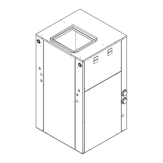
Page 7: Figure 1 Unit Dimensions
Manual 2100-545E Page 7 of 38... -
Page 8: Heater Package Nomenclature
Circuit Wire Volts/Phase Models Model No. Ampacity Breaker Size+ 60 HZ AMPS AMPS EH3GSVA-A05C 240/208-1 18.8 15,345 16.3 3.38 11,525 23.5 GV27S2AA & EH3GSVA-A09C 240/208-1 37.5 30,690 32.5 6.75 23,018 46.9 GV38S2AA EH3GSVA-A14C 240/208-1 56.3 13.5 46,035 48.7 10.13 34,543 70.4... -
Page 9: Application And Location
APPLICATION AND LOCATION GENERAL on the opposite side of the unit. (See Figure 2.) The two (2) access doors from the right hand return can be Units are shipped completely assembled and internally transferred to the left-hand return side and the one (1) wired, requiring only duct connections, thermostat left-hand panel can be transferred to the right hand wiring, 230/208 volt AC power wiring, and water... -
Page 10: Figure 2 Field-Conversion To Left Hand Return
FIGURE 2 FIELD CONVERSION TO LEFT-HAND RETURN Panel removed for clarity. Does not need removed to change control panel location. MIS-2617 1. Remove control panel fill plate. 2. Remove two screws securing control panel to unit. 3. Pass control panel through blower section rotating 180°. 4. -
Page 11: Filters
FILTER CONDENSATE DRAIN This unit must not be operated without a filter. It Drain lines must be installed according to local comes equipped with 2" disposable filters, which plumbing codes. It is not recommended that any should be checked often and replaced if dirty. condensate drain line be connected to a sewer main. -
Page 12: Figure 3 Filter Rack Configuration
Manual 2100-545E Page 12 of 38... -
Page 13: Figure 4 Piping Access
FIGURE 4 CONDENSATE DRAIN & PIPING ACCESS TO UNIT Water in connection MIS-2619 Water out connection Condensate drain access (4) locations Desuperheater Pump module connections 1/2" I.D. copper stub Manual 2100-545E Page 13 of 38... -
Page 14: Wiring Instructions
WIRING INSTRUCTIONS GENERAL TABLE 6 CONTROL CIRCUIT WIRING All wiring must be installed in accordance with the National Electrical Code and local codes. In Canada, Maximum Total Rated VA of Transformer all wiring must be installed in accordance with the Distance of Control Circuit Secondary FLA... -
Page 15: Figure 5 Thermostat Wiring
FIGURE 5 THERMOSTAT WIRING GROUND LOOP APPLICATIONS (when utilized with a flow center) 8403-060 (1120-445) W1/E D/YO (See notes 1 & 2 below) Unit 24V terminal strip GROUND WATER APPLICATIONS (when installed with recommended motorized valve with end switch) 8403-060 (1120-445) W1/E D/YO (See notes 1 &... -
Page 16: Ground Loop
GROUND LOOP (EARTH COUPLED WATER LOOP APPLICATIONS) NOTE: pressure of head loss in 1/2 inch or 3/4 inch household plumbing. A closed loop earth coupled heat pump Unit shipped from factory with 60 PSIG low pressure system, however, is separated from the pressure of the switch wired into control circuit and must be household supply and relies on a small, low wattage rewired to 45 PSIG low pressure switch for ground... -
Page 17: Start Up Procedure For Ground Loop System
START UP PROCEDURE FOR GROUND recheck the selection of the loop pump module model for sufficient capacity. If the module LOOP SYSTEM selection is correct, there is probably trapped air or 1. Be sure main power to the unit is OFF at a restriction in the piping circuit. -
Page 18: Figure 7 Temperature & Pressure Measurement
FIGURE 7 FIGURE 7 Thermometer Thermometer NOTE: Slide retaining cap back to expose Dial face pressure guage NOTE: Slide retaining cap back to expose Dial face pressure guage double o-rings. Apply petroleum jelly to o-rings with guage adaptor double o-rings. Apply petroleum jelly to o-rings with guage adaptor to prevent damage and aid in insertion to prevent damage and aid in insertion... -
Page 19: Ground Water (Well System Applications)
GROUND WATER (WELL SYSTEM APPLICATIONS) NOTE: Constant Flow Valve (3) provides correct flow of water to the unit regardless of variations in water pressure. It is highly recommended on ground water systems Observe the water flow direction indicated by the arrow (pump &... -
Page 20: Figure 10 Water Connection Components
The pressure requirements put on the pump are that the piping is not undersized, which would create directly affected by the diameter of pipe being used, too much pressure due to friction loss. High pressure as well as, by the water flow rate through the pipe. losses due to undersized pipe will reduce efficiency The worksheet included should guarantee that the and require larger pumps and could also create water... -
Page 21: Start Up Procedure For Ground Water System
SYSTEM START UP PROCEDURE FOR WATER CORROSION GROUND WATER APPLICATIONS Two concerns will immediately come to light when considering a water source heat pump, whether for 1. Be sure main power to the unit is OFF at disconnect. ground water or for a ground loop application: Will 2. -
Page 22: Figure 11 Cleaning Water Coil
4. Scale Formation. Of all the water problems, the provide adequate filtration of the water to allow good performance of the ground water heat pump. formation of scale by ground water is by far the most common. Usually this scale is due to the The following is a list of recommendations to follow formation of calcium carbonate but magnesium when installing this type of system:... -
Page 23: Figure 12 Lake Or Pond Installation
C. If possible, use a submersible pump suspended in The drain line should be installed with a slope of the dry well casing. Jet pumps and other types of 2 inches per 10 feet of run to provide complete suction pumps normally consume more electrical drainage of the line when the ground water heat pump is not operating. -
Page 24: Sequence Of Operation
SEQUENCE OF OPERATION BLOWER PART LOAD HEATING (No Electric Heat) When thermostat system switch is placed in HEAT, the Blower functions are all automatic through the thermostat control. (See Table 1 for the specific reversing valve solenoid is no longer energized. On a airflows on each speed.) Motor control inputs are all call for part load heating, the thermostat completes 24 VAC with line power to motor being continuous. -
Page 25: Compressor Control Module
SEQUENCE OF OPERATION PRESSURE SERVICE PORTS COMPRESSOR CONTROL MODULE High and low pressure service ports are installed on The compressor control module is an anti-short cycle/ all units so that the system operating pressures can be lockout timer with high and low pressure switch observed. -
Page 26: Figure 13 Component Location
FIGURE 13 COMPONENT LOCATION LOW PRESSURE SWITCHES EXPANSION VALVE SUCTION SERVICE PORT DISCHARGE SERVICE PORT DESUPERHEAT COIL HIGH VOLTAGE IN FLOW CENTER POWER COMPRESSOR WATER COIL HIGH PRESSURE SWITCH REVERSING VALVE MIS-2625 FIGURE 14 CONTROL PANEL E. HEAT TERMINAL TERMINAL GROUND CIRCUIT TRANSFORMER... -
Page 27: Figure 15 Refrigerant Flow Diagrams
FIGURE 15 Manual 2100-545E Page 27 of 38... -
Page 28: Figure 16A Pressure Tables
Manual 2100-545E Page 28 of 38... -
Page 29: Figure 16B Pressure Tables
FIGURE 16B PRESSURE TABLES FULL LOAD COOLING — Fluid Temperature Entering Water Coil °F Return Model Pressure 30°F 35°F 40°F 45°F 50°F 55°F 60°F 65°F 70°F 75°F 80°F 85°F 90°F 95°F 100°F 105°F 110°F Temp. 75° DB Low Side 62° WB High Side 80°... -
Page 30: Quick Reference Troubleshooting Chart
Manual 2100-545 Page 30 of 38 Manual 2100-545E Page 30 of 38... -
Page 31: Service
SERVICE SERVICE HINTS COMPRESSOR SOLENOID 1. Caution owner to maintain clean air filters at all (See Sequence of Operation on Pages 24 & 25 for times. Also, not to needlessly close off supply and function.) A nominal 24-volt direct current coil return air registers. -
Page 32: Figure 17 Motor Connections
TROUBLESHOOTING GE X13-SERIES ECM MOTORS If the Motor is Running plate. If higher than allowed, additional duct work is needed. 1. It is normal for the motor to rock back and forth TROUBLESHOOTING GE X13-SERIES ECM2.3 ™ MOTORS If the motor does not shut off at the end of the on start up. -
Page 33: Figure 18 Motor Connections
TROUBLESHOOTING GE X13-SERIES ECM2.3 MOTORS ™ CONT’D. Model X13 Communication Diagnostics 2. Initiate a demand from the thermostat and check the voltage between the common and the The X13 motor is communicated through 24 VAC low appropriate motor terminal (1-5). (“G” input voltage (Thermostat Control Circuit Wiring). -
Page 34: Figure 19 Typical Pump Kit Connection
ACCESSORIES ADD-ON GVDM-26 PUMP MODULE KIT INSTALLATION NOTE: This section applies only if a GVDM-26 Pump 1. Follow all local, state, and national codes applicable Module is added. Refer to GVDM-26 instructions for to the installation of the pump module kit. complete installation details. -
Page 35: Ground Source Heat Pump Performance Report
Ground Source Heat Pump Performance Report Date: ____________________ Technician: __________________________________________ Company Reporting: ________________________ Contact Phone: ____________________________ Owner’s Name: ____________________________ Owner’s Address: ___________________________ 1. Model/Serial Numbers: (For 3‐Pc. Geo‐Trio system, include coil/compressor/blower information) Model Number(s): ______________________________________________________________ Serial Number(s): _______________________________________________________________ 2. Accessory Information: Thermostat Mfgr. _____________________ Model/Part Number: ___________________ Flow‐Center* Mfgr. _____________________ Model/Part Number: ___________________ *if applicable 3. Open‐Loop Water Source Information: Where/how is water discharged ___________________________________________________ 4. Closed‐Loop Water Source Information: Horizontal Trenches ... - Page 36 The following information is needed to verify performance of the system. Note: Before testing, disable desuperheater, auxiliary electric heat, and any ventilation equipment that may allow outdoor air into the system. Measurements should be taken after a minimum 10 min. run time to ensure “steady‐state” of operation. Temperature and pressure measurements should be taken with a single thermometer and pressure gauge to eliminate discrepancies between multiple devices. Fluid Data: Stg. Cool Stg. Cool Stg. Heat Stg. Heat 5. Entering Fluid Temperature °F __________ __________ __________ __________ 6. Leaving Fluid Temperature °F __________ __________ __________ __________ 7. Entering Fluid Pressure psi __________ __________ __________ __________ 8. Leaving Fluid Pressure psi __________ __________ __________ __________ 9. Pressure Drop through coil (psi) __________ ...
-
Page 37: Wiring Diagrams
Manual 2100-545E Page 37 of 38... - Page 38 Line 2 Line 1 230/208-60-1 Power Source Circuit Circuit Terminal Terminal Breaker Breaker Block Block Compressor Capacitor 4 Pin Plug for Indoor Blower Motor Transformer 24VAC High Pressure Control Compressor Emergency Contactor Heat Relay Comp. Low Pressure Control Control Module Blower Control 3 Pin Heater...
Need help?
Do you have a question about the GV27S2AA and is the answer not in the manual?
Questions and answers