Table of Contents
Advertisement
Quick Links
Advertisement
Table of Contents

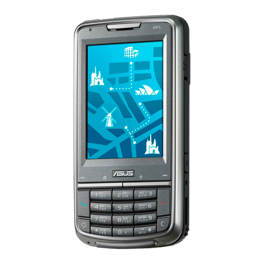
Summary of Contents for Asus P526
- Page 1 TSD ■ Service Manual P526 Service Manual...
-
Page 2: Equipments Required
TSD ■ Service Manual 1.Equipments required Equipment ASUS Part# Supplier Quantity Remarks Description Computer None None SIM Card None None P526 80A-S5C1004 ASUS Battery 07G016043459 ASUS Mini USB 14G000506200 ASUS cable Screwdriver 16-T00362002 ASUS (T5) Tweezers 16-000600014 ASUS Plastic 13GV0400PZZZ... -
Page 3: Disassembly / Assembly Procedure
TSD ■ Service Manual 2. Disassembly / Assembly Procedure 2.1 Introduction This section describes how to disassemble P526 telephone. Many of the integrated devices used in this phone are vulnerable to damage. Ensure adequate static protection is in place when handling, shipping, and servicing any internal components. -
Page 4: Disassembly Procedure
TSD ■ Service Manual 2.3 Disassembly Procedure The following set of diagrams will demonstrate the correct sequence and action to disassemble P526. 1. Remove the Stylus 2. Remove Battery cover 3. Remove Battery... - Page 5 TSD ■ Service Manual 4. Remove the ANTENNA Cover 5. Remove 4 SCREWS M1.6*4L T5 6. Disassemble FRONT COVER ASS'Y and MIDDLE COVER ASS'Y by Plastic Wrench...
- Page 6 TSD ■ Service Manual 7. Remove VIBRATOR and SPEAKER from MIDDLE COVER ASS'Y 8. Remove Main Board from FRONT COVER ASS'Y...
- Page 7 TSD ■ Service Manual 9. Remove LCD TFT, KEYPAD and 4 GASKETS from FRONT COVER ASS'Y 10. Remove RECEIVER from FRONT COVER ASS'Y...
-
Page 8: Assembly Procedure
TSD ■ Service Manual 2.4 Assembly Procedure It is carried out in the exact reverse sequence as the disassembly. 1. Assemble FRONT COVER ASS'Y: Put RECEIVER in FRONT COVER ASS'Y 2. Assemble LCD module 3.Put Keypad in FRONT COVER ASS'Y... - Page 9 TSD ■ Service Manual 4. Assemble FRONT COVER ASS'Y and Main Board 5.Connect the LCM Module 6. Assemble MIDDLE COVER ASS'Y:Put VARISTOR in MIDDLE COVER ASS'Y...
- Page 10 TSD ■ Service Manual 7.Put OK KEY MIDDLE COVER ASS'Y 8.Put CAMERA KEY in MIDDLE COVER ASS'Y 9.Put POWER KEY in MIDDLE COVER ASS'Y 10.Assemble MIDDLE COVER ASS'Y and MIDDLE COVER ASS'Y...
- Page 11 TSD ■ Service Manual 11.Put on 4 SCREWS M1.6*4L T5 12.Put on Battery 13.Put on Battery Cover...
- Page 12 TSD ■ Service Manual 14. Assemble Styluses:Put in Stylus...


Need help?
Do you have a question about the P526 and is the answer not in the manual?
Questions and answers