Makita LS1440 Instruction Manual
Miter saw
Hide thumbs
Also See for LS1440:
- Instruction manual (97 pages) ,
- Instruction (37 pages) ,
- Instruction manual (81 pages)

Subscribe to Our Youtube Channel
Related Manuals for Makita LS1440


Summary of Contents for Makita LS1440
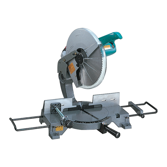
- Page 1 Miter Saw MODEL LS1440 002146 DOUBLE INSULATION I N S T R U C T I O N M A N U A L WARNING: For your personal safety, READ and UNDERSTAND before using. SAVE THESE INSTRUCTIONS FOR FUTURE REFERENCE.
-
Page 2: Specifications
SPECIFICATIONS Blade diameter..............................355 mm Hole diameter..........................25 mm and 25.4 mm Max. Miter angle ..........................Left 45° , Right 45° Max. Cutting capacities (H x W) Miter angle 0° 45° (left and right) 122 mm x 152 mm 122 mm x 115 mm No load speed (min ) ............................. -
Page 3: General Safety Rules
GENERAL SAFETY RULES GEA001-3 WARNING: Read all instructions. Failure to follow all instructions listed below may result in electric shock, fire and/or serious injury. The term “power tool” in all of the warnings listed below refers to your mains-operated (corded) power tool or battery- operated (cordless) power tool. -
Page 4: Additional Safety Rules For Tool
22. Use the power tool, accessories and tool bits or storing power tools. Such preventive safety measures reduce the risk of starting the power tool etc. in accordance with these instructions and in accidentally. the manner intended for the particular type of power tool, taking into account the working con- 19. - Page 5 27. Select saw blades in relation to the material to reduce your exposure to these chemicals: work be cut. in a well ventilated area and work with approved safety equipment, such as those dust masks 28. Take care when slotting. that are specially designed to filter out micro- 29.
-
Page 6: Installation
INSTALLATION Bench mounting When the tool is shipped, the handle is locked in the lowered position by the 002147 handle latch. Release the handle latch by lowering the handle slightly and turn the handle latch to the released position. 1. Handle latch This tool should be bolted with four bolts to a level and stable surface using the 003638 bolt holes provided in the tool’s base. - Page 7 Kerf board 002150 This tool is provided with the kerf board in the turn base to minimize tearing on the exit side of a cut. If the kerf groove has not yet been cut in the kerf board by the factory, you should cut the groove before actually using the tool to cut a workpiece.
-
Page 8: Fence Plate
Always be sure that the tool is switched off and unplugged before installing or removing the blade. • Use only the Makita socket wrench provided to install or remove the blade. Failure to do so may result in overtightening or insufficient tightening of the hex bolt. This could cause an injury. - Page 9 Press the shaft lock to lock the spindle and use the socket wrench to loosen 002156 the hex bolt counterclockwise. Then remove the hex bolt, outer flange and blade. 1. Shaft lock 002243 1. Socket wrench To install the blade, mount it carefully onto the spindle, making sure that the 002860 direction of the arrow on the surface of the blade matches the direction of the arrow on the blade case.
-
Page 10: Securing Workpiece
Empty the dust bag of its contents, tapping it lightly so as to remove particles adhering to the insides which might hamper further collec- tion. NOTE: If you connect a Makita vacuum cleaner to your saw, more efficient and 1. Dust nozzle cleaner operations can be performed. 2. Dust bug 3. -
Page 11: Operation
Horizontal vise (Accessory) 002158 The horizontal vise can be installed on either the left or right side of the base. When performing 15° or greater miter cuts, install the horizontal vise on the side opposite the direction in which the turn base is to be turned. By turning the vise knob counterclockwise, the screw is released and the vise shaft can be moved rapidly in and out. - Page 12 leave a mark (saw mark) in the workpiece and the precision of the cut will be impaired. Press cutting 002159 Secure the workpiece with the vise. Switch on the tool without the blade making any contact and wait until the blade attains full speed before low- ering.
- Page 13 After changing the miter angle, cut the wood facing at that selected 003640 angle. If there is a gap between the blade, the wood facing and the work- piece, move the wood facing slightly in the direction of the arrow and cut it again.
-
Page 14: Maintenance
MAINTENANCE CAUTION: • Always be sure that the tool is switched off and unplugged before attempting to perform inspection or maintenance. WARNING: • Always be sure that the blade is sharp and clean for the best and safest performance. Adjusting the cutting angle This tool is carefully adjusted and aligned at the factory, but rough handling 002162 may have affected the alignment. -
Page 15: After Use
“Blade guard”. Lubricate the sliding portions with tool oil to prevent rust. To maintain product SAFETY and RELIABILITY, repairs, any other mainte- nance or adjustment should be performed by Makita Authorized Service Cent- ers, always using Makita replacement parts. - Page 16 CAUTION: • These accessories or attachments are recommended for use with your Makita tool specified in this manual. The use of any other accessories or attachments might present a risk of injury to persons. Only use accessory or attachment for its stated purpose.
- Page 17 Memo...
- Page 18 Memo...
- Page 19 Memo...
- Page 20 Makita Corporation 883619D8...
Need help?
Do you have a question about the LS1440 and is the answer not in the manual?
Questions and answers
replace torsion spring on ls1440 makita 14" chop saw