Table of Contents
Advertisement
Quick Links
Operator Manual
Gasoline containing up to 10% ethanol (E10) is
acceptable for use in this machine. The use of any
gasoline exceeding 10% ethanol (E10) will void
the product warranty.
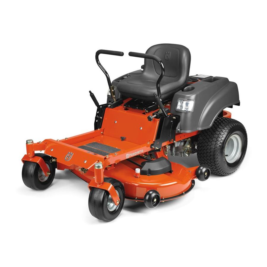
RZ46i / 967277604
Please read the operator manual carefully and make sure you
understand the instructions before using the machine.
Advertisement
Table of Contents

Related Manuals for Husqvarna RZ46i


Summary of Contents for Husqvarna RZ46i
- Page 1 The use of any gasoline exceeding 10% ethanol (E10) will void the product warranty. RZ46i / 967277604 Please read the operator manual carefully and make sure you understand the instructions before using the machine.
-
Page 2: Conformity Certificates
CONFORMITY CERTIFICATES USA requirements Labels are placed on the engine and/or in the engine compartment stating that the machine will fulfill the requirements. This is also applicable to special requirements for any of the states, (California emission rules etc.). Do not remove any of these labels. -
Page 3: Table Of Contents
CONTENTS INTRODUCTION ............... 4 Running ..............19 Driving and Transport on Public Roads ...... 4 Stopping the Engine ..........20 Towing ................. 4 Mowing Tips ............. 20 Operating ..............4 Operating On Hills ............ 21 Good Service .............. 5 Headlights ..............21 Manufacturing Number ......... -
Page 4: Introduction
INTRODUCTION Congratulations Operating Thank you for purchasing a Husqvarna ride-on mower. This This machine is constructed only for mowing grass on lawns machine is built for superior efficiency to rapidly mow primarily and even ground without obstacles such as stones, tree large areas. -
Page 5: Good Service
INTRODUCTION Good Service Husqvarna's products are sold only in specialized retail stores with complete service. This ensures that you as a customer receive only the best support and service. Before the product is delivered, the machine has, for example, been inspected and adjusted by your retailer. -
Page 6: Symbols And Decals
SYMBOLS AND DECALS These symbols are found on the machine and in the operator manual. Study them carefully so that you know what they mean. IMPORTANT INFORMATION Xxxx xxxxxx xxxxx xxxx WARNING! Xxxx xxxxxx xxxxx xxxx xxxxxxxxx xxxxxxxxx xxxxxx xxxxxxxxx. xx xxxxxxxx xxxx xxxxxx. xxxxxx xxxxxxxxx. -
Page 7: Safety Instructions
SAFETY Safety Instructions • Watch for traffic when operating near or crossing These instructions are for your safety. Read them carefully. roadways. General Operation • Use extra care when loading or unloading the machine into a trailer or WARNING! THIS CUTTING MACHINE IS CAPABLE truck. -
Page 8: Slope Operation
SAFETY Slope Operation Slopes are a major factor related to loss of control and tip-over WARNING! CHILDREN CAN BE INJURED BY accidents, which can result in severe injury or death. Operation THIS EQUIPMENT. The American Academy of Pediatrics on all slopes requires extra caution. If you cannot back up the recommends that children be a minimum of 16 years of age slope or if you feel uneasy on it, do not mow it. -
Page 9: General Maintenance
SAFETY • Never fill containers inside a vehicle or on a truck or trailer bed with plastic liner. Always place containers on the WARNING! The engine must not be started when ground away from the vehicle when filling. the driver’s floor plate or any protective plate for the mower •... -
Page 10: Transport
• Regularly clean deck and underside of deck, avoid A spark arrestor for the muffler is available through your spraying engine and electrical components with water. authorized Husqvarna dealer. Transport WARNING! Engine exhaust and certain vehicle WARNING! Use extreme caution when loading the components contain or emit chemicals considered to cause machine into a truck or trailer using ramps. -
Page 11: Control Locations
CONTROLS This operator manual describes the Husqvarna Zero Turn Rider. The rider is fitted with a Briggs & Stratton four-stroke overhead valve engine. Transmission from the engine is made via a belt-driven hydraulic pumps. Using the left and right steering controls, the flow is regulated and thereby the direction and speed. -
Page 12: Steering Control Levers
CONTROLS Steering Control Levers WARNING! The machine can turn very rapidly if one steering control is moved much further forward than the other. Ignition Switch The machine’s speed and direction are continuously variable using the two steering controls. The steering controls can be moved forward or backward about a neutral position. -
Page 13: Throttle Control
CONTROLS Throttle Control Service Meter The throttle control regulates the engine speed and the rate of The service meter displays the total number of hours the rotation of the blades, assuming the blade switch is pulled up. engine has run and indicates when the engine and mower need servicing. -
Page 14: Fuse
CONTROLS Fuse Cutting Height Lever The 20 amp primary fuse is located on the left hand side of the machine. It is accessed by tilting the seat forward. The fuse is IMPORTANT INFORMATION Always raise the deck to the a flat pin type used in automobiles. highest position for transport. -
Page 15: Fuel Tank
CONTROLS Fuel Tank WARNING! Gasoline is highly flammable. Observe caution and fill the tank outdoors (see the safety instruction). Park Brake WARNING! The engine and the exhaust system, become very hot during operation. Risk for burns if touched. Allow engine and exhaust system to cool before refueling. The park brake is found on the left of the machine. -
Page 16: Operation
OPERATION Complete Start Ignition Read the Safety section and following pages, if you are unfamiliar with the machine. NOTES: The default passcode [321] is preset at the factory. For safety and security, the passcode should be changed prior to Training use. -
Page 17: Before Starting
OPERATION Before Starting Starting the Engine Read the sections on Safety and Controls before starting Sit on the seat. the machine. Raise the mower deck by pushing the release button on Perform the daily maintenance before starting (see the top of the lifting lever. Pull the lifting lever backward to Maintenance Schedule in the Maintenance section). - Page 18 OPERATION Move the steering controls outward to the locked (outer) Enter the passcode and press the S/S button. The S/S neutral position. button will flash one slow green blink if the code is accepted and will change to a rapid green blink. If the S/S button has accepted the code but does not stay lit with a rapid green blink, see Ignition System Faults on the following page.
-
Page 19: Ignition System Faults
OPERATION Running Ignition System Faults The Complete Start Ignition is programmed to warn Release the park brake by pushing the top release button when any part of the safety system is not being followed in and moving the lever downward. NOTE: The mower is equipped with an operator presence and will not allow the unit to be started until all system system. -
Page 20: Stopping The Engine
OPERATION Stopping the Engine Mowing Tips Move the throttle to the minimum position (tortoise symbol). WARNING! Clear the lawn of stones and other objects that can be thrown out by the blades. • Observe and flag rocks and other fixed objects to avoid collisions. -
Page 21: Operating On Hills
OPERATION Operating On Hills Weak Battery Read the Safety Instructions Driving on Slopes in the Safety If the battery is too weak to start the engine, it should be section. recharged. (See Battery in the Maintenance section.) • The slowest speed possible should be used before starting If jumper cables are used for emergency starting, follow this up or down hills. -
Page 22: Battery Voltage Light
OPERATION Moving Machine By Hand Battery Voltage Light A battery voltage light can indicate that voltage is below When pushing or pulling the mower, engage the EZT bypass the normal operating power. linkages. The EZT bypass linkages are located on the rear of the frame, below the rear engine guard. -
Page 23: Maintenance Schedule
MAINTENANCE Maintenance Schedule The following is a list of maintenance procedures that must be recommended to maintain your machine in the best possible performed on the machine. For those points not described in condition and to ensure safe operation. this manual, visit an authorized service workshop. An annual Read General Maintenance in the Safety section. - Page 24 MAINTENANCE At least Maintenance interval Daily once in hours each MAINTENANCE Before After year ■ Check/adjust throttle cable ● ● Check the condition of belts, belt pulleys ■ ■ Change the engine oil ■ ■ Replace the engine oil filter ■...
-
Page 25: Battery
MAINTENANCE Battery STANDARD STATE APPROXIMATE BATTERY CHARGING TIME* TO FULL CHARGE AT 80 F / 27 Your mower is equipped with a maintenance free battery and BATTERY Maximum Rate at: does not need servicing. However, periodic charging of the CHARGE battery with an automotive type battery charger will extend its 50 Amps 30 Amps... -
Page 26: Safety System
Perform a standstill test and check that there is sufficient braking action. The engine can only be started when: To adjust the park brake, contact the Husqvarna service • The mower deck is disengaged. workshop. -
Page 27: Caster Wheels
MAINTENANCE Caster Wheels V-belts Check every 200 hours. Check that wheels rotate freely. If Check every 100 hours of operation. Check for severe wheels do not rotate freely take the unit to your dealer for cracking and large nicks. service. NOTE: The belt will show some small cracks in normal Foam filled tires or solid tires will void the warranty. -
Page 28: Leveling Deck
MAINTENANCE Adjusting the Mower Deck Turn either blade to align with the deck front-to-rear. If the front blade tip does not measure " to ½" higher in the Leveling deck rear, follow the front adjustment instructions that follow. Adjust the deck while the mower is on a level surface. With a or adjustable wrench, turn the nuts on the front Make sure the tires are inflated to the correct pressure. -
Page 29: Cutting Blades
CAUTION! Use protective glasses when cleaning and washing. IMPORTANT INFORMATION Special blade bolt is heat Hardware treated. Replace with a Husqvarna bolt if required. Do not use lower grade hardware than specified. Check daily. Inspect the entire machine for loose or missing hardware. -
Page 30: Lubrication
Transmission The transmission is maintenance free with no need for level checks or oil changes. If a leak occurs, replace the unit or contact your Husqvarna dealer. -
Page 31: Troubleshooting
TROUBLESHOOTING Problem / Cause Engine will not start Engine overheats Blade switch is engaged Clogged air intake or cooling fins Steering controls are not locked in the neutral position Engine overloaded Park brake is not activated Poor ventilation around engine Battery is dead Defective engine speed regulator Contamination in the carburetor or fuel line... -
Page 32: Storage
Never use Always use genuine Husqvarna spare parts. gasoline for cleaning. Use a degreaser and warm water An annual check-up at an authorized service workshop is a instead. -
Page 33: Schematic
SCHEMATIC... -
Page 34: Technical Data
TECHNICAL DATA Engine Frame Manufacturer Briggs & Stratton Cutting Width 117 cm Type 44S777 Cutting Height 3.8 - 10.2 cm Power 15.3 kW @ 3350 RPM Uncut Circle Lubrication Pressure with oil filter Number of Blades Fuel Min 87 octane unleaded (Max Blade Length 58 cm ethanol 10%, Max MTBE 15%) -
Page 35: Torque Specifications
TECHNICAL DATA Torque Specifications Standard ¼" fasteners 9 ft/lb (12 Nm) Engine crankshaft bolt 75 ft/lb (100 Nm) Standard " fasteners 18 ft/lb (25 Nm) Deck pulley bolts 75 ft/lb (100 Nm) Standard " fasteners 33 ft/lb (44 Nm) Lug nuts 75 ft/lb (100 Nm) Standard "... -
Page 36: Service Journal
SERVICE JOURNAL Action Date, mtr reading, stamp, sign Delivery Service Charge the battery Adjust the tire pressure of all wheels to 15 PSI (1 bar) Mount the steering controls in the normal position Connect the contact box to the cable for the seat’s safety switch Check that the right amount of oil is in the engine Adjust the position of the steering controls Fill with fuel and open the fuel shut off valve... -
Page 37: Hour Service
SERVICE JOURNAL Action Date, mtr reading, stamp, sign After the First 10 Hours Change engine oil Date, mtr reading, stamp, sign 25-Hour Service Check the fuel pump’s air filter Sharpen/Replace mower blades if required Check the tire pressures Check battery with cables Lubricate according to lubrication chart Check/clean the engine’s cooling air intake Clean the air cleaner’s foam pre-filter... - Page 38 SERVICE JOURNAL Action Date, mtr reading, stamp, sign 100-Hour Service Perform the 25-hour service Perform the 50-hour service Change the engine oil filter Clean/replace the spark plugs Replace the fuel filter Check V-belts Check tighten caster wheel axle bolts (every 200 hours) Change the air filter’s paper cartridge Change hydraulic pump oil and filter.
- Page 39 SERVICE JOURNAL Action Date, mtr reading, stamp, sign At Least Once Each Year Clean the engine’s cooling air intake (25 hours) Replace the air cleaner’s foam pre-filter (300 hours) Replace the air filter’s paper cartridge Change the engine oil (50 hours) Replace the engine oil filter (100 hours) Check/adjust the cutting height Check/adjust the park brake (50 hours)
- Page 40 115 681128 Rev A 2014-02-15...
Need help?
Do you have a question about the RZ46i and is the answer not in the manual?
Questions and answers