Table of Contents
Advertisement
www.nordictrack.com
Model No. NTEL05011.0
USER'S MANUAL
Serial No.
Write the serial number in the space
above for reference.
Serial Number Decal
QUESTIONS?
If you have questions, or if parts
are damaged or missing, DO NOT
CONTACT THE STORE; please
contact Customer Care.
IMPORTANT: Please register this
product (see the limited warranty
on the back cover of this manual)
before contacting Customer Care.
CALL TOLL-FREE:
1-800-TO-BE-FIT
(1-800- 862-3348)
Mon.–Fri., 6 a.m.–6 p.m. MT
Sat. 8 a.m.–4 p.m. MT
ON THE WEB:
www.nordictrackservice.com
CAUTION
Read all precautions and instruc-
tions in this manual before using
this equipment. Keep this manual
for future reference.
Advertisement
Table of Contents

Related Manuals for NordicTrack NTEL05011.0


Summary of Contents for NordicTrack NTEL05011.0
- Page 1 Model No. NTEL05011.0 USER’S MANUAL Serial No. Write the serial number in the space above for reference. Serial Number Decal QUESTIONS? If you have questions, or if parts are damaged or missing, DO NOT CONTACT THE STORE; please contact Customer Care.
-
Page 2: Table Of Contents
Apply the decal in the location shown. Note: The decal(s) may not be shown at actual size. NORDICTRACK is a registered trademark of ICON IP, Inc. -
Page 3: Important Precautions
IMPORTANT PRECAUTIONS WARNING: To reduce the risk of serious injury, read all important precautions and instructions in this manual and all warnings on your elliptical before using your elliptical. ICON assumes no responsibility for personal injury or property damage sustained by or through the use of this product. -
Page 4: Before You Begin
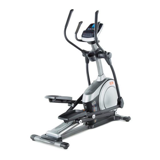
BEFORE YOU BEGIN Thank you for selecting the revolutionary reading this manual, please see the front cover of this NORDICTRACK ® E 5.7 elliptical. The E 5.7 elliptical manual. To help us assist you, note the product model provides an impressive selection of features designed number and serial number before contacting us. -
Page 5: Part Identification Chart
PART IDENTIFICATION CHART Use the drawings below to identify the small parts needed for assembly. The number in parentheses below each drawing is the key number of the part, from the PART LIST near the end of this manual. The number following the key number is the quantity needed for assembly. -
Page 6: Assembly
ASSEMBLY • Assembly requires two persons. • In addition to the included tool(s), assembly requires the following tools: • Place all parts in a cleared area and remove the one Phillips screwdriver packing materials. Do not dispose of the packing materials until you complete all assembly steps. -
Page 7: Of The Packing Materials (Not Shown) Under The
3. With the help of a second person, place some of the packing materials (not shown) under the front of the Frame (1). Have the second per- son hold the Frame to prevent it from tipping while you complete this step. Attach the Front Stabilizer (6) to the Frame (1) with two M10 x 122mm Button Screws (104) and two M10 Split Washers (105). - Page 8 5. Tip: Avoid pinching the Upper Wire (110). Set the Upright (4) on the Frame (1). Avoid pinching the Attach the Upright (4) with four M10 x 25mm Upper Wire (110) Button Screws (131) and four M10 Split Washers (105). 6.
- Page 9 7. Identify the Right Upper Body Arm (61), which is marked with a “Right” sticker, and orient it as shown. Slide the Right Upper Body Arm (61) onto the Right Upper Body Leg (60). Attach the Right Upper Body Arm (61) with two M8 x 38mm Button Bolts (96) and two M8 Locknuts (102).
- Page 10 9. Tip: Avoid pinching the wires. Attach the Console (7) to the Upright (4) with four M4 x 16mm Screws (101). Avoid pinching the wires 10. Identify the Right Pedal Arm (58), which is marked with a “Right” sticker, and orient it as shown.
- Page 11 11. Orient the Right Pedal Arm (58) as shown. Apply grease to the axle on the Right Pedal Arm (58). Attach the Right Pedal Arm (58) to the Right Roller Arm (59) with an M8 x 13mm Button Screw (82), a Small Axle Cover (55), and an M8 Washer (97).
- Page 12 13. Orient the Rear Upright Cover (81) as shown. Attach the Rear Upright Cover (81) to the Upright (4) with four M4 x 16mm Screws (101). Orient the Front Upright Cover (117) as shown. Attach the Front Upright Cover (117) around the Upright (4) by pressing the hooks on the Rear Upright Cover (81) onto the tabs on the Front Upright Cover.
- Page 13 15. Identify the Right Upper Body Leg Inner Cover (83), which is marked with a “Right” sticker, and orient it as shown. Attach the Right Upper Body Leg Inner Cover (83) to the Right Upper Body Leg (60) with an M4 x 16mm Screw (101) and an M5 Washer (132).
- Page 14 17. Orient the Rear Console Cover (80) as shown. Attach the Rear Console Cover (80) to the Upright (4) with two M4 x 16mm Screws (101). Orient the Front Console Cover (79) as shown. Attach the Front Console Cover (79) around the Upright (4) by pressing the hooks on the Rear Console Cover (80) onto the tabs on the Front Console Cover.
-
Page 15: How To Use The Elliptical
HOW TO USE THE ELLIPTICAL HOW TO PLUG IN THE POWER ADAPTER HOW TO LEVEL THE ELLIPTICAL IMPORTANT: If the elliptical has been exposed to If the elliptical rocks cold temperatures, allow it to warm to room tem- slightly on your perature before you plug in the power adapter. - Page 16 HOW TO EXERCISE ON THE ELLIPTICAL To mount the elliptical, hold the handlebars or the Upper upper body arms and step onto the pedal that is in the Body Arms lower position. Then, step onto the other pedal. Push the pedals until they begin to move with a continuous motion.
- Page 17 CONSOLE DIAGRAM FEATURES OF THE CONSOLE The advanced console offers an array of features designed to make your workouts more effective and enjoyable. When you use the manual mode of the console, you can change the resistance of the pedals with the touch of a button.
- Page 18 HOW TO USE THE MANUAL MODE Distance (Dist.)—This display mode will show the distance that you have pedaled in miles or 1. Begin pedaling or press any button on the kilometers. console to turn on the console. Pulse—This display mode will show your heart rate When you turn on the console, the display will light.
- Page 19 Press the Home button to return to the default When your pulse is detected, a heart symbol in the menu (see HOW TO CHANGE CONSOLE calorie display will flash each time your heart beats, SETTINGS on page 22 to set the default menu). one or two dashes will appear, and then your heart If necessary, press the Home button again.
- Page 20 HOW TO USE AN ONBOARD WORKOUT As you exercise, you will be prompted to keep your pedaling speed near the target speed for the 1. Begin pedaling or press any button on the current segment. When an upward-pointing arrow console to turn on the console. appears in the display, increase your pace.
- Page 21 HOW TO USE AN IFIT LIVE WORKOUT 5. Start the workout. 1. Begin pedaling or press any button on the See step 3 on page 20. console to turn on the console. During some workouts, the voice of a personal When you turn on the console, the display will light.
- Page 22 HOW TO USE THE SOUND SYSTEM 5. Determine if an iFit Live module is connected to the console. To play music or audio books through the console sound system while you exercise, plug the included If an iFit Live module is connected to the console, audio cable into the jack on the console and into a jack the display will show the words WIFI MODULE or on your MP3 player or CD player;...
-
Page 23: Fcc Information
FCC INFORMATION This equipment has been tested and found to comply with the limits for a Class B digital device, pursuant to part 15 of the FCC Rules. These limits are designed to provide reasonable protection against harmful interference in a residential installation. This equipment generates, uses, and can radiate radio frequency energy and, if not installed and used in accordance with the instructions, may cause harmful interference to radio communications. -
Page 24: Maintenance And Troubleshooting
MAINTENANCE AND TROUBLESHOOTING I nspect and tighten all parts of the elliptical regularly. Note: For clarity, the left shield is shown removed in the Replace any worn parts immediately. drawing below. To clean the elliptical, use a damp cloth and a small Next, locate the Reed Switch (38). - Page 25 HOW TO ADJUST THE DRIVE BELT See EXPLODED DRAWING C on page 31. Remove the M4 x 19mm Screws (5) and the M4 x 48mm Screw If the pedals slip while you are pedaling, even while (107) from the Left and Right Shields (73, 74). Then, the resistance is adjusted to the highest level, the drive remove the Right Shield.
-
Page 26: Exercise Guidelines
EXERCISE GUIDELINES Burning Fat—To burn fat effectively, you must exer- WARNING: cise at a low intensity level for a sustained period of Before beginning this time. During the first few minutes of exercise, your or any exercise program, consult your physi- body uses carbohydrate calories for energy. -
Page 27: Part List
PART LIST Model No. NTEL05011.0 R0911A Key No. Qty. Description Key No. Qty. Description Frame Roller Rear Stabilizer Pedal Arm Rear Cap Ramp Large Axle Cover Upright 16mm Wave Washer M4 x 19mm Screw Small Axle Cover Front Stabilizer Roller Arm Bushing... - Page 28 Key No. Qty. Description Key No. Qty. Description M4 x 16mm Screw M4 x 30mm Screw M8 Locknut Plastic Spacer M6 x 12mm Button Screw M4 Nut M10 x 122mm Button Screw Motor Bracket Screw M10 Split Washer M3.5 x 12mm Flat Head Screw Cover Mount Adjustment Nut M4 x 48mm Screw...
-
Page 29: Exploded Drawing
EXPLODED DRAWING A Model No. NTEL05011.0 R0911A... - Page 30 EXPLODED DRAWING B Model No. NTEL05011.0 R0911A...
- Page 31 EXPLODED DRAWING C Model No. NTEL05011.0 R0911A...
-
Page 32: Ordering Replacement Parts
ORDERING REPLACEMENT PARTS To order replacement parts, please see the front cover of this manual. To help us assist you, be prepared to provide the following information when contacting us: • the model number and serial number of the product (see the front cover of this manual) •...
Need help?
Do you have a question about the NTEL05011.0 and is the answer not in the manual?
Questions and answers