Table of Contents
Advertisement
Available languages
Available languages
Advertisement
Table of Contents

Related Manuals for MSI H67MA-E35 B3 series


Summary of Contents for MSI H67MA-E35 B3 series
- Page 1 H67MA-E35 (B3)/ H67MS-E23 (B3) series MS-7680 (v2.x) Mainboard G52-76801XT...
-
Page 2: Trademarks
Alternatively, please try the following help resources for further guidance. ◙ Visit the MSI website for technical guide, BIOS updates, driver updates, and other information: http://www.msi.com/service/download ◙ Contact our technical staff at: http://support.msi.com... -
Page 3: Safety Instructions
MS-7680 MS-7680 Safety Instructions ■ Always read the safety instructions carefully. ■ Keep this User’s Manual for future reference. ■ Keep this equipment away from humidity. ■ Lay this equipment on a reliable flat surface before setting it up. ■ The openings on the enclosure are for air convection hence protects the equipment from overheating. -
Page 4: Fcc-B Radio Frequency Interference Statement
Preface Preface FCC-B Radio Frequency Interference Statement This equipment has been tested and found to comply with the limits for a Class B digi- tal device, pursuant to Part 15 of the FCC Rules. These limits are designed to provide reasonable protection against harmful inter- ference in a residential installation. -
Page 5: Weee (Waste Electrical And Electronic Equipment) Statement
MSI will comply with the product take back requirements at the end of life of MSI-branded products that are sold into the EU. - Page 6 MSI će poštovati zahtev o preuzimanju ovakvih proizvoda kojima je istekao vek trajanja, koji imaju MSI oznaku i koji su prodati u EU. Ove proiz- vode možete vratiti na lokalnim mestima za prikupljanje.
- Page 7 MSI si adeguerà a tale Direttiva ritirando tutti i prodotti marchiati MSI che sono stati venduti all’interno dell’Unione Europea alla fine del loro...
-
Page 8: Table Of Contents
Preface Preface Contents Copyright Notice .................... ii Trademarks ....................ii Revision History..................... ii Technical Support..................ii Safety Instructions ..................iii FCC-B Radio Frequency Interference Statement.......... iv WEEE (Waste Electrical and Electronic Equipment) Statement ....v English ...................... En-1 Mainboard Specifications ...................En-2 Quick Components Guide ..................En-4 Screw Holes .......................En-5 CPU (Central Processing Unit) ................En-6... - Page 9 MS-7680 MS-7680 Français ..................... Fr-1 Spécifications ......................Fr-2 Guide Rapide Des Composants ................Fr-4 Trous Taraudés ....................Fr-5 Processeur : CPU ....................Fr-6 Mémoire ......................Fr-10 Connecteurs d’alimentation ................Fr-12 Panneau arrière ....................Fr-13 Connecteurs ......................Fr-15 Cavalier ......................Fr-21 Emplacements ....................Fr-22 Réglage BIOS ....................Fr-23 Information Logiciel ...................Fr-32 Русский ....................Ru-1 Характеристики...
-
Page 11: English
English H67MA-E35 (B3)/ H67MS-E23 (B3) Series Europe version... -
Page 12: Mainboard Specifications
Pentium / Celeron processor in the LGA1155 ® ® ® package (For the latest information about CPU, please visit http://www.msi.com/service/cpu-support) Chipset ■ Intel H67 (B3) chipset ® Memory Support ■ 2 DDR3 DIMMs support DDR3 1333/ 1066 DRAM (16GB Max) ■... - Page 13 ■ Micro-ATX (24.5 cm X 21.5 cm) Mounting ■ 6 mounting holes * If you need to purchase accessories and request the part numbers, you could search the product web page and find details on our web address http://www.msi.com/index. En-3...
-
Page 14: Quick Components Guide
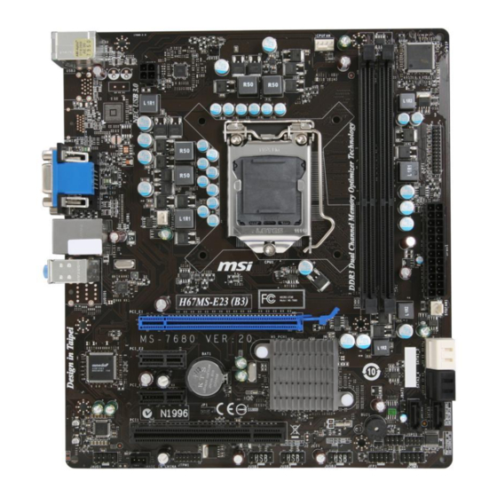
MS-7680 Mainboard MS-7680 Mainboard Quick Components Guide SYSFAN2, En-16 CPUFAN, En-16 CPU, En-6 JPWR2, En-12 DDR3, En-10 Back Panel, JLPT1, En-20 En-13 JBAT1, En-21 JPWR1, En-12 SYSFAN1, En-16 PCIE, En-22 SATA, En-15 PCI, En-22 JAUD1, En-17 JCOM1, En-18 JSP1, En-18 JFP1, JFP2, En-16 JTPM1, En-19 JCI1, En-20... -
Page 15: Screw Holes
Screw Holes When you install the mainboard, you have to place the mainboard into the chassis in the correct direction. The locations of screws holes on the mainboard are shown as below. The side has to toward the rear, the position for the I/O shield of the chassis. -
Page 16: Cpu (Central Processing Unit
When you are installing the CPU, make sure to install the cooler to prevent overheating. If you do not have the CPU cooler, consult your dealer before turning on the computer. For the latest information about CPU, please visit http://www.msi.com/service/cpu-support Important Overheating Overheating will seriously damage the CPU and system. -
Page 17: Cpu & Cooler Installation
CPU & Cooler Installation When you are installing the CPU, make sure the CPU has a cooler attached on the top to prevent overheating. Meanwhile, do not forget to apply some thermal paste on CPU before installing the heat sink/cooler fan for better heat dispersion. Follow the steps below to install the CPU &... - Page 18 MS-7680 Mainboard MS-7680 Mainboard Visually inspect if the CPU is seated Engage the load lever while pressing well into the socket. If not, take out down lightly onto the load plate. the CPU with pure vertical motion and reinstall. Alignment Key Secure the lever near the hook end Make sure the four hooks are in por- under the retention tab.
- Page 19 Align the holes on the mainboard with Press the four hooks down to fasten the heatsink. Push down the cooler the cooler. until its four clips get wedged into the holes of the mainboard. Turn over the mainboard to confirm Finally, attach the CPU Fan cable to that the clip-ends are correctly in- the CPU fan connector on the main-...
-
Page 20: Memory
MS-7680 Mainboard MS-7680 Mainboard Memory These DIMM slots are used for installing memory modules. For more information on compatible components, please visit http://www.msi.com/service/test-report DDR3 240-pin, 1.5V 48x2=96 pin 72x2=144 pin Dual-Channel mode Population Rule In Dual-Channel mode, the memory modules can transmit and receive data with two data bus lines simultaneously. -
Page 21: Installing Memory Modules
Installing Memory Modules The memory module has only one notch on the center and will only fit in the right orientation. Insert the memory module vertically into the DIMM slot. Then push it in until the golden finger on the memory module is deeply inserted in the DIMM slot. The plastic clip at each side of the DIMM slot will automatically close when the memory module is properly seated. -
Page 22: Power Supply
MS-7680 Mainboard MS-7680 Mainboard Power Supply ATX 24-pin Power Connector: JPWR1 This connector allows you to connect an ATX 24-pin power supply. To connect the ATX 24-pin power supply, make sure the plug of the power supply is inserted in the proper orientation and the pins are aligned. -
Page 23: Back Panel
Back Panel Mouse/ Keyboard VGA Port (optional) Line-In RS-Out USB 3.0 Port Line-Out CS-Out USB 2.0 Port HDMI Port DVI-D Port USB 2.0 Port SS-Out (optional) (optional) ▶ Mouse/Keyboard The standard PS/2 mouse/keyboard DIN connector is for a PS/2 mouse/keyboard. ®... - Page 24 MS-7680 Mainboard MS-7680 Mainboard ▶ The standard RJ-45 LAN jack is for connection to Yellow Green/ Orange the Local Area Network (LAN). You can connect a network cable to it. Color LED State Condition Left Yellow LAN link is not established. On(Steady state) LAN link is established.
-
Page 25: Connectors
Connectors Serial ATA Connector: SATA1~6 This connector is a high-speed Serial ATA interface port. Each connector can connect to one Serial ATA device. * The MB layout in this figure is for reference only. SATA6 SATA1~2 (6Gb/s) SATA1_2 SATA3~6 (3Gb/s) SATA3_4 SATA5 Important... - Page 26 MS-7680 Mainboard MS-7680 Mainboard Fan Power Connectors: CPUFAN,SYSFAN1~2 The fan power connectors support system cooling fan with +12V. When connecting the wire to the connectors, always note that the red wire is the positive and should be con- nected to the +12V; the black wire is Ground and should be connected to GND. If the mainboard has a System Hardware Monitor chipset on-board, you must use a specially designed fan with speed sensor to take advantage of the CPU fan control.
- Page 27 Front USB Connector: JUSB1~3 This connector, compliant with Intel I/O Connectivity Design Guide, is ideal for con- ® necting high-speed USB interface peripherals such as USB HDD, digital cameras, MP3 players, printers, modems and the like. * The MB layout in this figure is for reference only. USB Bracket (optional) Important Note that the pins of VCC and GND must be connected correctly to avoid possible...
- Page 28 MS-7680 Mainboard MS-7680 Mainboard S/PDIF-Out Connector: JSP1 This connector is used to connect S/PDIF (Sony & Philips Digital Interconnect Format) interface for digital audio transmission. * The MB layout in this figure is for reference only. S/PDIF-Out Bracket (optional) Serial Port Connector: JCOM1 This connector is a 16550A high speed communication port that sends/receives 16 bytes FIFOs.
- Page 29 TPM Module connector: JTPM1 This connector connects to a TPM (Trusted Platform Module) module (optional). Please refer to the TPM security platform manual for more details and usages. En-19...
- Page 30 MS-7680 Mainboard MS-7680 Mainboard Parallel Port Connector: JLPT1 This connector is used to connect an optional parallel port bracket. The parallel port is a standard printer port that supports Enhanced Parallel Port (EPP) and Extended Capa- bilities Parallel Port (ECP) mode. Chassis Intrusion Connector: JCI1 This connector connects to the chassis intrusion switch cable.
-
Page 31: Jumper
Jumper Clear CMOS Jumper: JBAT1 There is a CMOS RAM on board with an external battery power supply to preserve the system configuration data. With the CMOS RAM, the system can automatically boot OS every time it is turned on. If you want to clear the system configuration, please temporarily short these two pins to clear data by using a metal object. -
Page 32: Slots
MS-7680 Mainboard MS-7680 Mainboard Slots PCIE (Peripheral Component Interconnect Express) Slot The PCIE slot supports the PCIE interface expansion card. PCIE x16 Slot PCIE x1 Slot PCI (Peripheral Component Interconnect) Slot The PCI slot supports LAN card, SCSI card, USB card, and other add-on cards that comply with PCI specifications. -
Page 33: Bios Setup
BIOS Setup This chapter provides basic information on the BIOS Setup program and allows you to configure the system for optimum use. You may need to run the Setup program when: ■ An error message appears on the screen during the system booting up, and requests you to run BIOS SETUP. -
Page 34: Control Keys
MS-7680 Mainboard MS-7680 Mainboard Control Keys <↑><↓> Select Item <←><→> Select Screen <Enter> Select <Esc> Jumps to the Exit menu or returns to the main menu from a submenu <+><-> Change Option <F1> General Help <F6> Load Optimized Defaults <F10> Save all the CMOS changes and exit Getting Help After entering the Setup menu, the first menu you will see is the Main Menu. -
Page 35: The Menu Bar
The Menu Bar ▶ Main Menu Use this menu for basic system configurations, such as time, date etc. ▶ Advanced Use this menu to setup the items of the BIOS special enhanced features, integrated peripherals, power management and PC health status. ▶... - Page 36 MS-7680 Mainboard MS-7680 Mainboard When enter the BIOS Setup utility, follow the processes below for general use. Load Optimized Defaults : Use the arrow keys (←, →, ↑, ↓) to select the [Restore Defaults] in [Save & Exit] menu, and press <Enter>. A pop-up message will appear, please select [Yes] and press<Enter>...
- Page 37 Adjusted CPU Frequency It shows the adjusted CPU frequency. Read-only. ▶ Adjust CPU Ratio in OS Enable this item, it will allow you to change the CPU ratio in OS by using MSI applica- tion. ▶ Internal PLL Overvoltage This item are used to adjust the PLL voltage.
- Page 38 MS-7680 Mainboard MS-7680 Mainboard ▶ DRAM Ratio This setting controls the ratio of memory frequency to enable the memory to run at dif- ferent frequency combinations. ▶ Adjusted DRAM Frequency It shows the adjusted DRAM frequency. Read-only. ▶ DRAM Timing Mode Select whether DRAM timing is controlled by the SPD (Serial Presence Detect) EE- PROM on the DRAM module.
- Page 39 ▶ tRRD Specifies the active-to-active delay of different banks. ▶ tRTP Time interval between a read and a precharge command. ▶ tFAW This item is used to set the tFAW (four activate window delay) timing. ▶ tWCL This item is used to set the tWCL (Write CAS Latency) timing. ▶...
- Page 40 MS-7680 Mainboard MS-7680 Mainboard ▶ CPU Features Press <Enter> to enter the sub-menu. ▶ Hyper-threading The processor uses Hyper-Threading technology to increase transaction rates and reduces end-user response times. The technology treats the two cores inside the processor as two logical processors that can execute instructions simultaneously. In this way, the system performance is highly improved.
- Page 41 ▶ OverSpeed Protection Overspeed Protection function can monitor the current CPU draws as well as its power consumption. If it exceeds a certain level, the processor automatically reduces its clock speed. If you want to overclock your CPU, set it to [Disabled]. ▶...
-
Page 42: Software Information
Product info menu : It shows the newly information of MSI product. Security menu : It provides the useful antivirus program. Important Please visit the MSI officially website to get the latest drivers and BIOS for better system performance. En-32... -
Page 43: Deutsch
Deutsch H67MA-E35 (B3)/ H67MS-E23 (B3) Serie Europe Version... -
Page 44: Spezifikationen
/Core i3/ Pentium / Celeron Prozessor für Sockel ® ® ® LGA1155 (Weitere CPU Informationen finden Sie unter http://www.msi.com/service/cpu-support) Chipsatz ■ Intel H67 (B3) Chipsatz ® Speicher ■ 2 DDR3 DIMMs unterstützen DDR3 1333/ 1066 DRAM (max. 16GB) ■... - Page 45 1 PCIE x16-Steckplatz ■ 2 PCIE x1-Steckplätze ■ 1 PCI-Steckplatz Form Faktor ■ Micro-ATX (24,5 cm X 21,5 cm) Montage ■ 6 Montagebohrungen * Wenn Sie für Bestellungen von Zubehör Teilenummern benötigen, finden Sie diese auf unserer Produktseite unter http://www.msi.com/index.php De-3...
-
Page 46: Komponenten-Übersicht
MS-7680 Mainboard Komponenten-Übersicht SYSFAN2, De-16 CPUFAN, De-16 CPU, De-6 JPWR2, De-12 DDR3, De-10 Rücktafel, JLPT1, De-20 De-13 JBAT1, De-21 JPWR1, De-12 SYSFAN1, De-16 PCIE, De-22 SATA, De-15 PCI, De-22 JAUD1, De-17 JCOM1, De-18 JSP1, De-18 JFP1, JFP2, De-16 JTPM1, De-19 JCI1, De-20 JUSB1~3, De-17 De-4... -
Page 47: Schraubenlöcher
Schraubenlöcher Wenn Sie das Mainboard zu installieren, müssen Sie das Mainboard in das Chassis in der korrekten Richtung setzen. Die Standorte von Schraubenlöchern auf dem Main- board sind wie nachfolgend gezeigt. Die Seite muss nach hinten, die Position für die E/A-Abschirmung des Chassis. -
Page 48: Cpu (Prozessor
Sie sich bitte mit Ihrem Händler in Verbindung, um einen solchen zu erwerben und zu installieren. Um die neuesten Informationen zu unterstützten Prozessoren zu erhalten, besuchen Sie bitte http://www.msi.com/service/cpu-support Wichtig Überhitzung Überhitzung beschädigt die CPU und das System nachhaltig. Stellen Sie stets eine korrekte Funktionsweise des CPU Kühlers sicher, um die CPU vor Überhitzung zu... - Page 49 CPU & Kühler Einbau Wenn Sie die CPU einbauen, stellen Sie bitte sicher, dass Sie auf der CPU einen Kühler anbringen, um Überhitzung zu vermeiden. Vergessen Sie nicht, etwas Siliziumwärmel- eitpaste auf die CPU aufzutragen, bevor Sie den Prozessorkühler installieren, um eine Ableitung der Hitze zu erzielen.
- Page 50 MS-7680 Mainboard Begutachten Sie, ob die CPU richtig Schließen Sie die Abdeckung des im Sockel sitzt. Falls nicht, zeihen Sie Sockels und drücken Sie den Ver- die CPU durch eine rein vertikale Be- schlusshebel mit leichtem Druck wegung wieder heraus. Versuchen nach unten.
- Page 51 Drücken Sie den Verschlusshebel Führen Sie den CPU-Kühler über mit leichtem Druck nach unten und den CPU-Sockel. arretieren Sie den Hebel unter dem Rückhaltehaken des CPU-Sockels. Drehen Sie das Mainboard um und Schließlich verbinden vergewissern Sie sich, dass das der Stromkabel des CPU Lüfters mit dem Kühler korrekt installiert ist.
-
Page 52: Speicher
MS-7680 Mainboard Speicher Diese DIMM-Steckplätze nehmen Arbeitsspeichermodule auf. Die neusten Informa- tionen über kompatible Bauteile finden Sie unter http://www.msi.com/service/test-report DDR3 240-polig, 1,5V 48x2=96 Pole 72x2=144 Pole Populationsregeln für Dual-Kanal-Speicher Im Dual-Kanal-Modus können Arbeitsspeichermodule Daten über zwei Datenbusleitun- gen gleichzeitig senden und empfangen. Durch Aktivierung des Dual-Kanal-Modus wird die Leistung Ihres Systems verbessert. - Page 53 Vorgehensweise beim Einbau von Speicher Modulen Die Speichermodulen haben nur eine Kerbe in der Mitte des Moduls. Sie passen nur in einer Richtung in den Sockel. Stecken Sie das Arbeitsspeichermodul senkrecht in den DIMM-Steckplatz ein. Drücken Sie anschließnd das Arbeitsspeichermodul nach unten, bis die Kontakt- seite richtig tief in dem DIMM-Steckplatz sitzt.
-
Page 54: Stromversorgung
MS-7680 Mainboard Stromversorgung ATX 24-poliger Stromanschluss: JPWR1 Mit diesem Anschluss verbinden Sie den ATX 24-poligen Anschluss des Netzteils. Achten Sie bei dem Verbinden des ATX 24-poligen Stromanschlusses darauf, dass der Anschluss des Netzteils richtig auf den Anschluss an der Hauptplatine ausgerichtet ist. -
Page 55: Rücktafel
Rücktafel Maus/ Tastatur VGA Anschluss (optional) Line-In RS-Out USB 3.0 Anschluss Line-Out CS-Out USB 2.0 HDMI Anschluss DVI-D Anschluss USB 2.0 SS-Out Anschluss Anschluss (optional) (optional) ▶ Maus/Tastatur Die Standard PS/2 Maus/Tastatur Stecker DIN ist für eine PS/2 Maus/Tastatur. ® ®... - Page 56 MS-7680 Mainboard zu dienen. Wenn Sie einen Prozessor ohne integrierten Grafikchip installiert haben, haben diese DisplayPosts keine funktion. ▶ Die Standard RJ-45 Buchse ist für Anschlus zum Gelb Grün/ Orange an ein Lokales Netzwerk (Local Area Network - LAN). Hier kann ein Netzwerkkabel angeschlossen werden.
-
Page 57: Anschlüssen
Anschlüssen Serial ATA Anschluss: SATA1~6 Der Anschluss ist eine Hochgeschwindigkeitsschnittstelle der Serial ATA. Pro An- schluss kann ein S-ATA Gerät angeschlossen werden. * Das MB-Layout in dieser Abbildung haben nur Orientierungscharakter. SATA6 SATA1~2 (6Gb/s) SATA1_2 SATA3~6 (3Gb/s) SATA3_4 SATA5 Wichtig Bitte falten Sie das Serial ATA Kabel nicht in einem Winkel von 90 Grad, da dies zu Datenverlusten während der Datenübertragung führt. - Page 58 MS-7680 Mainboard Stromanschlüsse für Lüfter: CPUFAN,SYSFAN1~2 Die Anschlüsse unterstützen aktive Systemlüfter mit +12V. Wenn Sie den Anschluss herstellen, sollten Sie immer darauf achten, dass der rote Draht der positive Pol ist, und mit +12V verbunden werden sollte. Der schwarze Draht ist der Erdkontakt und sollte mit GND verbunden werden.
- Page 59 USB Vorderanschluss: JUSB1~3 Dieser Anschluss entspricht den Richtlinien des Intel I/O Connectivity Design Guide. ® Er ist bestens geeignet, Hochgeschwindigkeits- USB- Peripheriegeräte anzuschließen, wie z.B. USB Festplattenlaufwerke, Digitalkameras, MP3-Player, Drucker, Modems und ähnliches. * Das MB-Layout in dieser Abbildung haben nur Orientierungscharakter. USB Slotblech (optional) Wichtig Bitte beachten Sie, dass Sie die mit VCC (Stromführende Leitung) und GND (Erdlei-...
- Page 60 MS-7680 Mainboard S/PDIF-Ausgang: JSP1 Die S/PDIF (Sony & Philips Digital Interconnect Format) Schnittstelle wird für die Über- tragung digitaler Audiodaten verwendet. * Das MB-Layout in dieser Abbildung haben nur Orientierungscharakter. S/PDIF-Ausgang Slotblech (optional) Serieller Anschluss: JCOM1 Es handelt sich um eine 16550A Kommunikationsschnittstelle, die 16 Bytes FIFOs sendet/empfängt.
- Page 61 TPM Anschluss: JTPM1 Dieser Anschluss wird für das optionale TPM Modul (Trusted Platform Module) ver- wendt. Weitere Informationen über den Einsatz des optionalen TPM Modules entnehm- en Sie bitte dem TPM Plattform Handbuch. De-19...
- Page 62 MS-7680 Mainboard Parallele Schnittstelle: JLPT1 Die Parallele Schnittstelle ist eine Standard Druckerschnittstelle, die ebenso als En- hanced Parallel Port (EPP) und als Extended Capabilities Parallel Port (ECP) betrieben werden kann. Gehäusekontaktanschluss: JCI1 Dieser Anschluss wird mit einem Kontaktschalter verbunden. Wird das Gehäuse geöff- net, wird der Schalter geschlossen und das System zeichnet dies auf und gibt auf dem Bildschirm eine Warnung aus.
-
Page 63: Steckbrücke
Steckbrücke Steckbrücke zur CMOS- Löschung: JBAT1 Der Onboard CMOS Speicher (RAM) wird über eine zusätzliche Betterie mit Strom versorgt, um die Daten der Systemkonfiguration zu speichern. Er ermöglicht es dem Betriebssystem, mit jedem Einschalten automatisch hochzufahren. Wenn Sie die Systemkonfiguration löschen wollen, kurzschließen Sie diese zwei Pins durch ein Metallgegenstand für kurze Zeit, um die Daten zu löschen. -
Page 64: Steckplätze
MS-7680 Mainboard Steckplätze PCIE (Peripheral Component Interconnect Express) Steckplatz Der PCIE-Steckplatz unterstützt eine Erweiterungskarte mit der PCIE-Schnittstelle. PCIE x16-Steckplatz PCIE x1-Steckplatz PCI (Peripheral Component Interconnect) Steckplatz Der PCI-Steckplatz kann LAN-Karten, SCSI-Karten, USB-Karten und sonstige Zusatz- karten aufnehmen, die mit den PCI-Spezifikationen konform sind. 32-Bit PCI-Steckplatz Wichtig Achten Sie darauf, dass Sie zuerst das Netzkabel aus der Steckdose herausziehen,... -
Page 65: Bios Setup
BIOS Setup Dieses Kapitel enthält Informationen über das BIOS Setup und ermöglicht es Ihnen, Ihr System optimal auf Ihre Anforderungen einzustellen. Notwendigkeit zum Aufruf des BIOS besteht, wenn: ■ Während des Bootvorgangs des Systems eine Fehlermeldung erscheint und Sie zum Aufruf des BIOS SETUP aufgefordert werden. ■... - Page 66 MS-7680 Mainboard Steuertasten <↑><↓> Auswahl eines Eintrages <←><→> Auswahl eines Screen <Enter> Auswahl eines Bildschirm <Esc> Aufruf Exit Menü oder zurück zum Hauptmenü von Untermenü <+><-> Änderung der Option <F1> Allgemeine Hilfe <F6> Laden der ursprünglichen Setup-Standardwerte <F10> Speichern alle Änderungen im CMOS und beeden Hilfe finden Nach dem Start des Setup Menüs erscheint zuerst das Hauptmenü.
- Page 67 Die Menüleise ▶ Main Menu In diesem Menü können Sie die Basiskonfiguration Ihres Systems anpassen, so z.B. Uhrzeit, Datum usw. ▶ Advanced Verwenden Sie dieses Menü, um eigene weitergehende Einstellungen an Ihrem System, integrierte Peripheriegeräte, die Stromsparfunktionen und der PC-Gesundheitszustand vorzunehmen.
- Page 68 MS-7680 Mainboard Wenn Sie das BIOS Dienstprogramm öffnen, folgen Sie den untenstehenden An- weisungen. Laden der gespeicherten Werkseinstellung : Durch die Steuertasten (←, →, ↑, ↓) können Sie [Restore Defaults] in [Save & Exit]-Menü wählen und drücken Sie auf <Eingabe>. Und dann zeigt der Bildschrim die folgende PopUp-Meldung. Wählen Sie [Yes (Ja)] und klicken darauf, um die Standardeinstellungen für eine sichere Systemleistung zu laden.
- Page 69 Gibt die Frequenz der CPU an. Nur Anzeige – keine Änderung möglich. ▶ Adjust CPU Ratio in OS Aktivieren Sie dieses Element, können Sie die CPU-Verhältnis im Betriebssystem än- dern, indem Sie die MSI-Anwendung verwenden. ▶ Internal PLL Overvoltage Diese Option bietet Ihnen an, die PLL-Spannung anzupassen.
- Page 70 MS-7680 Mainboard ▶ DRAM Ratio Die Einstellung steuert das Verhältnis der Speicher-Frequenz, um unterschiedliche Kombinationen der Speicherfrequenzen einzustellen. ▶ Adjusted DRAM Frequency Zeigt die Speicherfrequenz an. Nur Anzeige – keine Änderung möglich. ▶ DRAM Timing Mode Wählen Sie aus, wie das DRAM-Timing durch das SPD (Serial Presence Detect) EE- PROM des DRAM-Moduls gesteuert wird.
- Page 71 der Zelle vor dem Lesebefehl zu überschreiben. ▶ tRRD Legt die Aktiv-zu-Aktiv Verzögerung für unterschiedliche Bänke fest. ▶ tRTP Legt das Zeitintervall zwischen dem Lesebefehl und dem vorgeladenen Befehl fest. ▶ tFAW Einstellen des tFAW -Zeitintervalls (four activate window delay). ▶...
- Page 72 MS-7680 Mainboard ▶ DRAM Voltage Diese Option bietet Ihnen an, die Spannung des Speichers anzupassen. ▶ CPU Features Drücken Sie die Eingabetaste <Enter>, um das Untermenü aufzurufen. ▶ Hyper-threading Der Prozessor verwendet die Technologie des Hyper-Threadings, um Verhandlun- grate zu erhöhen und die Antwortzeiten des Benutzers zu verringern. Die Tech- nologie behandelt den dual-core Prozessor als zwei logische Prozessoren, die Anweisungen gleichzeitig durchführen können.
- Page 73 tung, je nach Einstellung bzw. Bedarf. Nicht alle Prozessor unterstützt Enhanced Halt Stand (C1E). ▶ OverSpeed Protection Die Funktion des "Overspeed Protection" kann den aktuellen CPU Status sowie seine Leistungsaufnahme überwachen. Wenn es ein bestimmtes Niveau übersteigt, verringert der Prozessor automatisch seine Taktrate. Wollen Sie Ihre CPU Übertakten, deaktivieren Sie diese Option [Disabled].
-
Page 74: Software-Information
Produktinformation-Menü : Es zeigt die neu Informationen von MSI Produkt. Sicherheits-Menü : Es bietet die nützliche Antivirenprogramm. Wichtig Besuchen Sie bitte die offizielle Website des MSI, um die neuesten Treiber und BIOS für bessere System Leistung zu erhalten. De-32... -
Page 75: Français
Français H67MA-E35 (B3)/ H67MS-E23 (B3) Séries Europe version... -
Page 76: Spécifications
Pentium / Celeron processeurs dans le paquet ® ® ® LGA1155 (Pour plus d'information sur le CPU, veuillez visiter http://www.msi.com/service/cpu-support) Jeu de puces ■ Puces Intel H67 (B3) ® Mémoire supportée ■ 2 DDR3 DIMMs supportent DDR3 1333/ 1066 DRAM (16GB Max) ■... - Page 77 Micro-ATX (24.5 cm X 21.5 cm) Montage ■ 6 trous de montage * Si vous désirez acheter des accessoires et vous avez besoin de numéros des pièces, vous pouvez chercher sur la page website et trouver les détails sur notre adresse ci- dessous http://www.msi.com/index.php Fr-3...
-
Page 78: Guide Rapide Des Composants
Carte mère MS-7680 Guide Rapide Des Composants SYSFAN2, Fr-16 CPUFAN, Fr-16 CPU, Fr-6 JPWR2, Fr-12 DDR3, Fr-10 Panneau JLPT1, Fr-20 arrière, Fr-13 JBAT1, Fr-21 JPWR1, Fr-12 SYSFAN1, Fr-16 PCIE, Fr-22 SATA, Fr-15 PCI, Fr-22 JAUD1, Fr-17 JCOM1, Fr-18 JSP1, Fr-18 JFP1, JFP2, Fr-16 JTPM1, Fr-19 JCI1, Fr-20... -
Page 79: Trous Taraudés
Trous Taraudés Quand vous installez la carte mère, il faut déposer la carte dans le châssis en bonne position. La situation des trous taraudés sont montrée dans la figure ci-dessous. Face vers l’arrière, position pour la protège Entré/ Sortie du châssis. Trous taraudés Veuillez vous référer à... -
Page 80: Processeur : Cpu
Si vous n’en avez pas, contactez votre revendeu pour en acheter et in- stallez-les avant d’allumer votre ordinateur. Pour plus d’informations sur le CPU, veuillez visiter http://www.msi.com/service/cpu-support Important Surchauffe La surchauffe endommage sérieusement l’unité centrale et le système. Assurez-vous toujours que le ventilateur de refroidissement fonctionne correctement pour protéger... -
Page 81: Installation Du Cpu Et Son Ventilateur
Installation du CPU et son ventilateur Quand vous installez le CPU, assurez-vous que le CPU soit équipé d’un ventilateur de refroidissement attaché sur le dessus pour éviter la surchauffe. Méanmoins, n’oubliez pas d’appliquer une couche d’enduit thermique sur le CPU avant d’installer le ventila- teur pour une meilleure dissipation de chaleur. - Page 82 Carte mère MS-7680 Inspectez visuellement si le CPU Engagez le levier de charge en ap- est bien posé dans la douille. Sinon, puyant doucement sur le plaque de sortez verticalement le CPU pur et la charge. réinstallez. Clé d’alignement Sécurisez le levier à côté du bout de Assurez-vous que les quatre cro- crochet sous l’onglet de rétention.
- Page 83 Alignez les trous de la carte avec le Appuyez sur les quatre crochets afin dissipateur thermique. Appuyez sur de fixer le ventilateur. le ventilateur jusqu’à ce que les clips soient coincés dans les trous de la carte mère. Retournez la carte mère pour as- Finalement, attachez le câble du surer que le ventilateur est installé...
-
Page 84: Mémoire
Carte mère MS-7680 Mémoire Ces slots DIMM sont destinés à installer les modules de mémoire. Pour plus d’informations sur les composants compatibles, veuillez visiter http://www.msi.com/service/test-report DDR3 240-pin, 1.5V 48x2=96 pin 72x2=144 pin Règle de population en mode double-canaux En mode de canaux-double, les modules de mémoire peuvent transmettre et recevoir les données avec simultanément deux lignes omnibus de données. - Page 85 Installation des modules de mémoire Le module de mémoire possède une seule encoche en son centre et ne s’adaptera que s’il est orienté de la mqnière convenable. Insérez le module de mémoire à la verticale dans le slot du DIMM. Poussez-le en- suite jusqu’à...
-
Page 86: Connecteurs D'alimentation
Carte mère MS-7680 Connecteurs d’alimentation Connecteur d’alimentation ATX 24-pin : JPWR1 Ce connecteur vous permet de connecter l’alimentation ATX 24-pin. Pour cela, as- surez-vous que la prise d’alimentation est bien positionnée dans le bon sens et que les goupilles soient alignées. Enfoncez alors la prise dans le connecteur. Vous pourvez aussi utiliser un alimentation 20-pin selon vos besoins. -
Page 87: Panneau Arrière
Panneau arrière Souris/ Clavier Port VGA (en option) Ligne-In RS-Out Port USB 3.0 Ligne-Out CS-Out Port USB 2.0 Port HDMI Port DVI-D Port USB 2.0 SS-Out (en option) (en option) ▶ Souris/Clavier Le standard connecteur de souris/clavier DIN de PS/2 est pour une souris ou un clavier ®... - Page 88 Carte mère MS-7680 Important Les interfaces d'affichage HDMI, VGA et DVI-D sur la carte mère sont planifiés pour servir d'un IGP (Integrated Graphics Processor). Si vous avez installé un processeur sans la puce graphique intégrée, ces ports d'affichage n'auront aucun effet. ▶...
-
Page 89: Connecteurs
Connecteurs Connecteur Sérial ATA : SATA1~6 Ce connecteur est un port d’interface de série ATA haut débit. Chaque connecteur peut être relié à un appareil de série ATA. * Le schéma de carte mère dans la figure n’est qu’à titre de référence. SATA6 SATA1~2 (6Gb/s) SATA1_2... - Page 90 Carte mère MS-7680 Connecteur d’alimentation du ventilateur : CPUFAN,SYSFAN1~2 Les connecteurs de courant du ventilateur supportent le ventilateur de refroidissement du système avec +12V. Lors du branchement des fils aux connecteurs, faites toujours en sorte que le fil rouge soit le fil positif devant être relié au connecteur +12V; et que le fil noir soit le fil de mise à...
- Page 91 Connecteur USB avant : JUSB1~3 Ce connecteur est conforme au guide de conception de la connectivité Entrée/sortie du panneau avant Intel , il est idéal pour relier les périphériques d’interface USB à haut ® débit tels les disques durs externes, les appareils photo numériques, les lecteurs MP3, les imprimantes, les modems et les appareils similaires.
- Page 92 Carte mère MS-7680 Connecteur S/PDIF-Out : JSP1 Ce connecteur sert à connecter l’interface S/PDIF (Sony & Philips Digital Interconnect Format) pour une transmission audio numérique. * Le schéma de carte mère dans la figure n’est qu’à titre de référence. Support S/PDIF-Out (en option) Connecteur de port sérial : JCOM1 Le port serial est un port de communications de haute vitesse de 16550A, qui envoie/ reçoit 16 bytes FIFOs.
- Page 93 Connecteur du Module TPM : JTPM1 Ce connecteur est rélié à TPM (Trusted Platform Module) Module (en option). Veuillez vous référer au manuel de TPM plat-forme (en option) de sécurité pour plus de détails et d’utilisations. Fr-19...
- Page 94 Carte mère MS-7680 Connecteur de port parallèle : JLPT1 Ce connecteur sert à connecter un support de port parallèle optionnel. Le port paral- lèle est un port d’imprimante standard qui supporte les modes Enhanced Parallel Port (EPP) et Extended Capabilities Parallel Port (ECP). Connecteur Châssis Intrusion : JCI1 Ce connecteur est connecté...
-
Page 95: Cavalier
Cavalier Cavalier d’effacement CMOS : JBAT1 Il y a un CMOS RAM intégré, qui possède un bloc d’alimentation alimenté par une bat- terie externe, destiné à conserver les données de configuration du système. Avec le CMOS RAM, le système peut lancer automatiquement le système d’exploitation chaque fois qu’il est allumé. -
Page 96: Emplacements
Carte mère MS-7680 Emplacements Emplacement PCIE (Peripheral Component Interconnect Express) L’emplacement PCIE supporte la carte d’extension d’Interface PCIE. Emplacement PCIE x16 Emplacment PCIE x1 Emplacement PCI (Peripheral Component Interconnect) L’emplacement PCI supporte la carte LAN, la carte SCSI, la carte USB et d’autres cartes ajoutées qui sont compatibles avec les spécifications de PCI. -
Page 97: Réglage Bios
Réglage BIOS Ce chapitre donne des informations concernant le programme de réglage du BIOS et vous permet de configurer le système pour obtenir des performances d’utilisation opti- mum. Vous aurez peut-être besoin de lancer le programme de réglage lorsque : ■... - Page 98 Carte mère MS-7680 Touches de contrôle <↑><↓> Choisir un article <←><→> Choisir l’écran <Enter> Entrer <Esc> Retourner au menu Exit ou revenir à la page précédente d’un sous- menu <+><-> Option de changements <F1> Aide générale <F6> Charger les réglages optimaux par défaut <F10>...
- Page 99 La barre menu ▶ Main Menu Utilisez ce menu pour les configurations du système de base, tel que l’heure, la date. ▶ Advanced Utilisez ce menu pour régler les objets des fonctions améliorées spéciales du BIOS, les périphériques intégrés, la gestion d’alimentation et l’état de santé de l’ordinateur. ▶...
- Page 100 Carte mère MS-7680 Quand vous entrez dans l’unité de réglages BIOS, suivez les procédures suivantes pour l’utilisation générale. Load Optimized Defaults (Chargement des réglages optimisés par défaut) : Utilisez les touches de flèche (←, →, ↑, ↓) pour choisir [Restore Defaults] dans le menu [Save &...
- Page 101 Il montre la fréquence ajustée du CPU. Lecture uniquement. ▶ Adjust CPU Ratio in OS Activer ce menu, il vous permettra de changer le ratio CPU dans le système d’exploitation en utilisant l’application MSI. ▶ Internal PLL Overvoltage Ce menu sert à ajuster la tension PLL.
- Page 102 Carte mère MS-7680 ▶ DRAM Ratio Ce réglage contrôle le ratio de fréquence mémoire pour permettra à la mémoire de fonctionner avec des combinaisons de différentes fréquences. ▶ Adjusted DRAM Frequency Il montre la fréquence ajustée de la DRAM. Lecture uniquement. ▶...
- Page 103 ▶ tRRD Spécifie le retard active-à-active des différentes banques. ▶ tRTP L’intervalle de temps entre un ordre de lire et un ordre de pré-charge. ▶ tFAW Ce menu sert à régler le timing tFAW (délai de quatre fenêtres activées). ▶ tWCL Ce menu sert à...
- Page 104 Carte mère MS-7680 ▶ CPU Features Appuyez sur <Enter> pour entrer dans le sous-menu. ▶ Hyper-threading Le processeur utilise la Hyper-Threading Technologie pour augmenter le taux de transaction et réduire les réponses du dernier-utilisateur. La technologie prend les deux puces à l’intérieur du processeur pour deux processeurs logiques qui peuvent exécuter les instructions simultanément.
- Page 105 ▶ OverSpeed Protection La fonction Overspeed Protection permet de surveiller le CPU actuel ainsi que sa consommation d'énergie. Si elle surpasse un certain niveau, le processeur réduira automatiquement sa fréquence. Si vous voulez overclocker votre CPU, mettez le en [Disabled].. ▶...
-
Page 106: Information Logiciel
Menu d’information du produit : Il montre les nouvelles informations sur le produit MSI. Menu de sécurité : Il fournit la programme d’antivirus. Important Veuillez consulter le site Web de MSI pour obtenir les derniers pilotes et BIOS pour une meilleure performance du système. Fr-32... -
Page 107: Русский
Русский Серия H67MA-E35 (B3)/ H67MS-E23 (B3) Europe version... -
Page 108: Характеристики
® ® LGA1155 (Для получения самой новой информации о CPU, посетите сайт http://www.msi.com/service/cpu-support) Чипсет ■ Intel H67 (B3) ® Память ■ 2 слота DDR3 DIMM поддерживают скорость DDR3 1333/ 1066 DRAM (16ГБ Max) ■ Поддержка двухканального режима (За дополнительной информацией о совместимых компонентах посетите сайт... - Page 109 ■ 2 слота PCIE x1 ■ 1 слот PCI Форм Фактор ■ Micro-ATX (24.5 см X 21.5 см) Крепление ■ 6 отверстий для крепления * Помощь в приобретении дополнительных аксессуаров и поиске номера изделия можно найти по адресу http://www.msi.com/index.php Ru-3...
-
Page 110: Размещение Компонентов Системной Платы
MS-7680 Системная плата MS-7680 Системная плата Размещение компонентов системной платы SYSFAN2, Ru-16 CPUFAN, Ru-16 CPU, Ru-6 JPWR2, Ru-12 DDR3, Ru-10 Задняя JLPT1, Ru-20 панель, Ru-13 JBAT1, Ru-21 JPWR1, Ru-12 SYSFAN1, Ru-16 PCIE, Ru-22 SATA, Ru-15 PCI, Ru-22 JAUD1, Ru-17 JCOM1, Ru-18 JSP1, Ru-18 JFP1, JFP2, Ru-16 JTPM1, Ru-19... -
Page 111: Отверстия Для Винтов
Отверстия для винтов При установке системной платы нужно вставить её в корпус в правильном направлении. Размещения отверстий для винтов показаны ниже. Боковые стороны следует против заднего корпуса, размещение для протектора входа/ выхода корпуса. Отверстия для винтов Следуйте указаниям выше указанно для установки держателей в правильном месте в... -
Page 112: Cpu (Центральный Процессор
установить процессорный кулер. Если у вас нет процессорного кулера, пожалуйста, свяжитесь с дилером с целью приобретения и его установки до того, как включите компьютер. Последнюю информацию о поддержке процессоров можно получить на сайте http://www.msi.com/service/cpu-support Внимание Перегрев Перегрев может серьёзно повредить центральный процессор. Чтобы уберечь... - Page 113 Установка процессора и вентилятора Во избежание перегрева при работе обязательно установите вентилятор процессора. Одновременно, чтобы улучшить теплоотвод, убедитесь в том, что нанесён слой теплопроводящей пасты на процессоре перед установкой вентилятора. Следуйте данным указаниям для правильной установки. Неправильная установка приведет к повреждению процессора и системной платы. Потяните...
- Page 114 MS-7680 Системная плата MS-7680 Системная плата Визуально проверьте правильность Опустите металлическую крышку установки процессора в разъем. механизма крепления. Если процессор установлен неправильно, то выньте процессор и переустановите. Ключ для установки Опустите рычаг на крышку Перед установкой вентилятора механизма крепления и убедитесь, что...
- Page 115 Совместите отверстия системной Нажмите на четыре защелки и платы с защелками крепления закрепите вентилятор. вентилятора. Прижмите радиатор с вентилятором к процессору и проследите, чтобы четыре защелки вошли в отверстия системной платы. Переверните системную плату и По завершении подключите кабель убедитесь, что защелки надежно вентилятора...
-
Page 116: Память
MS-7680 Системная плата MS-7680 Системная плата Память Слоты DIMM используются для установки модулей памяти. За дополнительной информацией о совместимых компонентах обратитесь на сайт http://www.msi.com/service/test-report DDR3 240-конт, 1.5V 48x2=96 конт 72x2=144 конт Правила установки модулей памяти для работы в двухканальном режиме... - Page 117 Установка модулей памяти Модули памяти имеют одну прорезь в средней части. Модуль войдет в разьем только при правильной ориентации. Вставьте модуль в DIMM слот в вертикальном направлении. Затем нажмите на него, чтобы золоченые контакты глубоко погрузились в DIMM слот. Если модуль...
-
Page 118: Разъем Питания
MS-7680 Системная плата MS-7680 Системная плата Разъем питания 24-контактный разъем питания ATX: JPWR1 Этот разъем позволяет подключить 24-контактный коннектор питания ATX. Для его подключения убедитесь, что коннектор и контакты разъема правильно сориентированы. Затем плотно вставьте его в разъем на системной плате. Вы... -
Page 119: Задняя Панель
Задняя панель Разъем Порт мыши/ клавиатуры Порт VGA (опционально) Линейный RS-выход Порт USB 3.0 вход Линейный CS-выход выход Порт USB 2.0 Порт HDMI Порт DVI-D Порт USB 2.0 Микрофон SS-выход (опционально) (опционально) ▶ Порт мыши/клавиатуры Стандартные разъемы DIN PS/2 для подключения мыши/клавиатуры с ®... - Page 120 MS-7680 Системная плата MS-7680 Системная плата Внимание Интерфейсы дисплея HDMI, VGA и DVI-D на системной плате разработаны для использования в качестве IGP (Integrated Graphics Processor). Если вы установили процессор без встроенного графического чипа, эти порты работать не будут. ▶ Разъем LAN Стандартный...
-
Page 121: Коннекторы
Коннекторы Разъем Serial ATA: SATA1~6 Данный разъем является высокоскоростным портом интерфейса Serial ATA. Любой разъем Serial ATA может соединяться с одним устройством Serial ATA. * Компоненты системной платы в изображении только для справки. SATA6 SATA1~2 (6Гб/с) SATA1_2 SATA3~6 (3Гб/с) SATA3_4 SATA5 Внимание... - Page 122 MS-7680 Системная плата MS-7680 Системная плата Разъем питания вентиляторов: CPUFAN,SYSFAN1~2 Разъемы питания вентиляторов поддерживают вентиляторы с питанием +12В. При подключении необходимо помнить, что красный провод подключается к шине +12В, черный - к земле GND. Если на системной плате установлена микросхема аппаратного...
- Page 123 Разъем USB передней панели: JUSB1~3 Разъем, соответствует спецификации Intel I/O Connectivity Design и преднозначен ® для подключения высокоскоростных периферийных устройств, таких как USB HDD, цифровые камеры, MP3 плееры, принтеры, модемы и т.д. * Компоненты системной платы в изображении только для справки. Выносная...
- Page 124 MS-7680 Системная плата MS-7680 Системная плата Разъем S/PDIF-Out: JSP1 Этот разъем используется для подключения интерфейса S/PDIF (Sony & Philips Digital Interconnect Format) для передачи звука в цифровом формате. * Компоненты системной платы в изображении только для справки. Выносная планка S/PDIF-Out (опционально) Разъем...
- Page 125 Разъем TPM Модуля: JTPM1 Данный разъем подключается к модулю TPM (Trusted Platform Module) (опционально). За более подробной информацией и назначениями обращайтесь к описанию модуля TPM. Ru-19...
- Page 126 MS-7680 Системная плата MS-7680 Системная плата Разъем параллельного порта: JLPT1 Этот коннектор используется для подключения опциональной планки параллельного порта. Параллельный порт - это стандартный порт для принтера. Он поддерживает режимы EPP (усовершенствованный параллельный порт) и ECP (параллельный порт с дополнительными возможностями). Разъем...
-
Page 127: Перемычки
Перемычки Перемычки очистки CMOS: JBAT1 На плате установлена CMOS память с питанием от батарейки, хранящая данные о конфигурации системы. С помощью памяти CMOS, система автоматически загружается каждый раз при включении. Если у вас возникает необходимость сбросить конфигурацию системы (очистить CMOS), временно закорачивайте эти два... -
Page 128: Слоты
MS-7680 Системная плата MS-7680 Системная плата Слоты Слот PCIE (Peripheral Component Interconnect Express) Слот PCIE поддерживает карты расширения интерфейса PCIE. PCIE x16 слот PCIE x1 слот Слот PCI (Peripheral Component Interconnect) Слот PCI позволяет установить карты LAN, SCSI, USB и другие дополнительные карты... -
Page 129: Настройка Bios
Настройка BIOS В этой главе приводятся основные сведения о режиме настройки BIOS (BIOS SETUP), который позволяет установить оптимальную конфигурацию системы. Этот режим может потребоваться в следующих случаях: ■ Во время загрузки системы появляется сообщение об ошибке с требованием запустить BIOS SETUP. ■... - Page 130 MS-7680 Системная плата MS-7680 Системная плата Клавиши управления <↑><↓> Выбор пункта <←><→> Выбор экрана <Enter> Выбор <Esc> Переход в меню Выход или возвращение к предыдущему пункту в подменю <+><-> Опция для изменения <F1> Подробная справка <F6> Установка оптимальных настроек <F10> Сохранить...
- Page 131 Строка Меню ▶ Main Menu Это меню позволяет установить основные параметры конфигурации системы (дату, время и т.п.). ▶ Advanced Это меню используется для настройки специальных функций BIOS, периферийных устройств, управления питанием и состояния аппаратной части ПК. ▶ Overclocking Это меню позволяет управлять тактовыми частотами и напряжениями при разгоне системы.
- Page 132 MS-7680 Системная плата MS-7680 Системная плата Находясь в режиме настройки BIOS, рекомендуется выполнить следующие действия. Load Optimized Defaults : Клавишами стрелки (←, →, ↑, ↓) выберите пункт [Re- store Defaults] из меню [Save & Exit], нажмите <Enter>. И на экране появляется сообщение, выберите...
- Page 133 Этот пункт показывает текущую частоту CPU. Только для чтения. ▶ Adjust CPU Ratio in OS Включите этот пункт, он позволяет вам изменить частоту CPU в ОС средством приложения MSI. ▶ Internal PLL Overvoltage Этот пункт используется для регилирования напряжения PLL.
- Page 134 MS-7680 Системная плата MS-7680 Системная плата ▶ DRAM Ratio Пункт управления cоотношением частот памяти. ▶ Adjusted DRAM Frequency Этот пункт показывает текущую частоту DRAM. Только для чтения. ▶ DRAM Timing Mode Определяет будут ли тайменги DRAM контролироваться данными из SPD (Se- rial Presence Detect) EEPROM на...
- Page 135 ▶ tRRD Определяет задержку перехода от активного-к-активному состоянию для разных банков. ▶ tRTP Временный интервал между командами чтения и предзаряда. ▶ tFAW Этот пункт используется для установки таймингов tFAW (four activate window delay). ▶ tWCL Этот пункт используется для установки таймингов tWCL (Write CAS Latency). ▶...
- Page 136 MS-7680 Системная плата MS-7680 Системная плата ▶ DRAM Voltage Этот пункт используется для регулирования напряжения памяти. ▶ CPU Features Нажмите <Enter> для входа в подменю. ▶ Hyper-threading Процессор использует технологию Hyper-Threading для увеличения производительности. Эта технология позволяет двум наборам регистров в...
- Page 137 ▶ OverSpeed Protection Функция Overspeed Protection отображает поток вычислений CPU и его энергопотребление. Если оно превысит определённуый уровень, то процессор автоматически понизит тактовую частоту. Если вы собирайтесь разгонять CPU, то установите этот параметр в [Disabled]. ▶ Intel C-State C-state - это технология управления питанием, при ктивации которой значительно...
-
Page 138: Сведения О Программном Обеспечении
Service base menu (Меню сервисной базы): Позволяет соединить официальный вебсайт MSI. Product info menu (Меню продуктов): Показывает последнюю информацию о продуктах MSI. Security menu (Меню безопасности): Представляет полезные антивирусные программы. Внимание Пожалуйста, посетите вебсайт MSI для получения самых новых драйверов и BIOS, которые позволят улучшить производительность системы. Ru-32...
Need help?
Do you have a question about the H67MA-E35 B3 series and is the answer not in the manual?
Questions and answers