
Related Manuals for Sears 721.80522500


Summary of Contents for Sears 721.80522500
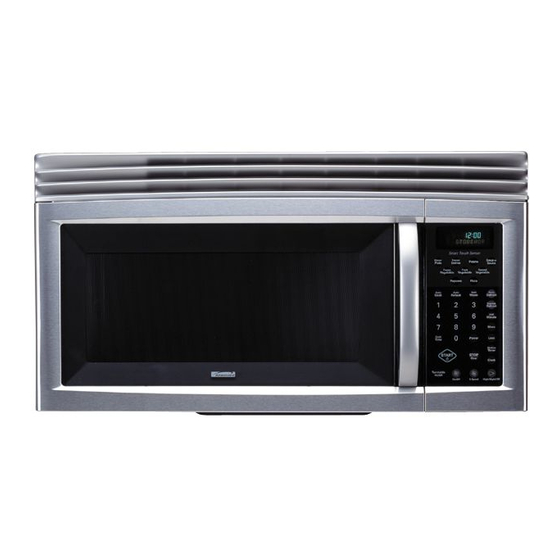
- Page 1 MODEL 721.80522 721.80529 721.80524 721.80523 DIVISION 22 BASIC FIELD MANUAL MICROWAVE HOOD COMBINATION MODEL 721.80522500 721.80529500 721.80524500 721.80523500 October, 2005...
-
Page 2: Warning To Service Technicians
CAUTION WARNING TO SERVICE TECHNICIANS PRECAUTIONS TO BE OBSERVED BEFORE AND DURING SERVICING TO AVOID POSSIBLE EXPOSURE TO EXCESSIVE MICROWAVE ENERGY a. Do not operate or allow the oven to be operated with the door open. b. Make the following safety checks on all ovens to be serviced before activating the magnetron or other microwave source, and make repairs as necessary;... -
Page 3: Table Of Contents
FOREWORD Read this Manual carefully. Failure to adhere to or observe the information in this Manual may result in exposing yourself to the Microwave Energy normally contained within the oven cavity. MODEL 721.80522 721.80529 721.80524 721.80523 TABLE OF CONTENTS (Page) SAFETY PRECAUTIONS ........................Inside front page SPECIFICATIONS .............................. -
Page 4: Specifications
SPECIFICATIONS Rated Power Consumption ........1560W maximum (Microwave oven+Cook top lamps+Ventilation fan) Microwave Output ..........1000W (IEC60705) Frequency ............2450 MHz ± 50 MHz Power Supply .............120 VAC, 60 Hz Rated Current ............13.3 Amp. (Microwave oven+Cook top lamps+Ventilation fan) Magnetron Cooling ..........Forced Air Cooling Rectification ............Rectification Voltage Double Half-Wave Door Sealing ............Choke System Safety Devices ...........Magnetron Thermostat: Open at 145 °C ±... -
Page 5: Cautions
CAUTIONS Unlike other appliances, the microwave oven is MICROWAVE RADIATION high-voltage and high-current equipment. Personnel should not be exposed to the Though it is free from danger in ordinary use, microwave energy which may radiate from the extreme care should be taken during repair. magnetron or other microwave generating device if it is improperly used or connection. -
Page 6: Installations
INSTALLATIONS BEFORE YOU BEGIN, READ THE FOLLOWING INSTRUCTIONS COMPLETELY AND CAREFULLY. PRECAUTIONS ON INSTALLATION A. Plug the power supply cord into a 120V AC, 60Hz, single-phase power source with a capacity of at least 20 amperes. B. Avoid placing the unit in a location where there is direct heat or splashing water. -
Page 7: Operating Instructions
OPERATING INSTRUCTIONS CONTROL PANEL... -
Page 8: Control Panel Instructions
CONTROL PANEL INSTRUCTIONS 1. Display. The display includes a clock and indicators 16. Express Defrost. Touch this pad to express to tell you time of day, cooking time settings, cook defrost. “GROUND BEEF 1.0 LBS TOUCH powers, quantities, weights and cooking functions START”... -
Page 9: Overall Circuit Diagram
OVERALL CIRCUIT DIAGRAM SCHEMATIC DIAGRAM... -
Page 10: Matrix Circuit For Touch Key Board
MATRIX CIRCUIT FOR TOUCH KEY BOARD KEY MATRIX Frozen Hold Frozen Express Canned Vegetable Warm Entree Defrost Vegetable VENT LIGHT Dinner VENT Soup or 5 Speed Plate HIigh/Night/Off Sauce On/Off Fresh Auto Auto Popcorn Pizza Potato Defrost Minute Reheat Vegetable Auto Kitchen Less... -
Page 11: General Information For Service
GENERAL INFORMATION FOR SERVICE GENERAL PRECAUTIONS IN USE FEATURES AND SPECIFICATIONS FEATURES A. Never operate the unit when it is empty. A. The safety systems incorporated in this model are: Operating the oven with no load may shorten the (1) Primary interlock switch life of the magnetron. -
Page 12: Service Information
SERVICE INFORMATION PRECAUTIONS AND REPAIR SERVICE TIPS PRELIMINARY (3) Do not operate the unit until it is completely repaired, if any of the following conditions exist. The unit must not be operated. A. SINCE NEARLY 4000 VOLTS EXISTS IN SOME (a) The door does not close firmly. -
Page 13: Microwave Leakage Test
MICROWAVE LEAKAGE TEST CAUTIONS EQUIPMENT- • Be sure to check microwave leakage prior to • TESTER ((VOLTS-DC, AC, Ohmmeter) servicing the oven if the oven is operative prior to • Microwave survey meter servicing. - Holaday HI-1500 • The service personnel should inform the HI-1501 manufacture importer, or assembler of any certified - Narda... -
Page 14: Power Output Measurement
MEASUREMENT WITH THE OUTER CASE NOTE WHEN MEASURING REMOVED (1) Do not exceed meter full scale deflection. (2) The test probe must be removed no faster than (1) When you replace the magnetron, measure for 1 inch/sec (2.5cm/sec)along the shaded area, microwave energy leakage before the outer case otherwise a false reading may result. -
Page 15: Disassembly Instructions
DISASSEMBLY INSTRUCTIONS IMPORTANT NOTES: (4) Remove 3 screws securing the circuit board. UNIT MUST BE DISCONNECTED FROM ELEC- TRICAL OUTLET WHEN MAKING REPAIRS, RE- PLACEMENTS, ADJUSTMENTS AND CONTIN- Circuit Board UITY CHECKS. WHEN RECONNECTING THE WIRE LEADS TO ANY PART, MAKE SURE THE WIRING CONNE- CTIONS AND LEAD COLORS ARE CORRECTLY MATCHED ACCORDING TO THE OVERALL CIR- CUIT DIAGRAM. - Page 16 HOW TO REMOVE THE F.P.C. CONNECTOR HOW TO INSERT THE F.P.C. CONNECTOR Follow the steps below as illustrated in Figures 4 Follow the steps below as illustrated in Figures 6 and 5 to remove the F.P.C. connector. and 7 to insert the F.P.C. connector. (1) Insert the F.P.C.
- Page 17 B. REMOVING THE OUTSIDE CASE (Figure 8) (1) Remove the vent grille by removing two screws securing it to the out case. (2) Remove two screws securing it to the air duct. (3) Remove the mounting plate by turning the screws (1 or 2 screws)securing it to the out case.
- Page 18 C. REMOVING THE DOOR INTERLOCK SWITCHES (Figures 9, 10) (1) Disconnect the wire leads from the interlock switches. (2) Remove two screws securing the Latch Board. (3) Make necessary replacements and check microwave energy leakage according to “ADJUSTMENT PROCEDURES” on page 7-12. Latch Board Primary Latch Board...
- Page 19 D. REMOVING MAGNETRON E. REMOVING STIRRER FAN (Figures 11 Through 12) (Figures 13 and 14) (1) Remove the vent grille by loosening two screws. (1) Remove one rivet ASS'Y securing it to the oven (Figure 11) upper plate by using knife blade. (2) Remove the outcase.
- Page 20 F. REMOVING DOOR (Figure 15) H. ASSEMBLING DOOR (1) Remove the vent grille by two screws securing it to (1) When mounting the door assembly to the oven the outcase loosening. assembly, be sure to adjust the door assembly (2) Lift up and draw the door. parallel to the chassis.
- Page 21 (3) Carefully pull the ventilation motor ASS'Y out of the J. REMOVING THE TURNTABLE MOTOR microwave oven. (See Figure 18-b) (1) Remove the glass tray and Hub. (2) Remove the turntable shaft VERY CAREFULLY with a hand. (Figure 19) (3) Remove the base plate by removing 8 screws securing it to the oven cavity.
- Page 22 K. REPLACING THE HUMIDITY SENSOR (1) Remove the sensor by removing two screws securing it to the air duct. (See Figure 22) (2) Mount the new humidity sensor to the air duct. Figure 22 7-11...
-
Page 23: Interlock System
INTERLOCK SYSTEM INTERLOCK MECHANISM The door lock mechanism is a device which has been specially designed to eliminate completely microwave activity when the door is opened during cooking and thus to prevent the danger resulting from the microwave leakage. ADJUSTMENT PROCEDURES CHECK THE DOOR LATCH AND SWITCH To avoid possible exposure to microwave energy CLOSING. - Page 24 TEST THE LATCH AND SWITCH SEQUENCE (7) When you achieve the proper sequence of switches in Steps 5 and 6, tighten the latch board screws at that point. (5) Open the oven door slowly. Watch the door latch, the Secondary Switch. Release Rod and Lever TEST THE MICROWAVE ENERGY LEAKAGE on the switches to make sure they are zero to the body of the switches in the following sequence:...
-
Page 25: Interlock Continuity Test
INTERLOCK CONTINUITY TEST A. PRIMARY INTERLOCK SWITCH TEST B. SECONDARY INTERLOCK SWITCH TEST When the door is opened slowly, an audible click Disconnect the wire lead from the secondary should be heard at the same time or successively switch. at intervals and the latches should activate the Connect the ohmmeter leads to the common switches with an audible click (COM)and normally open (NO)terminals of the... -
Page 26: Test And Checkout Procedures And Troubleshooting
TEST AND CHECKOUT PRECEDURES AND TROUBLESHOOTING CAUTIONS 1. DISCONNECT THE POWER SUPPLY CORD FROM THE OUTLET WHENEVER REMOVING THE OUTER CASE FROM THE UNIT. PROCEED WITH THE TEST ONLY AFTER DISCHARGING THE HIGH VOLTAGE CAPACITOR AND REMOVING THE LEAD WIRES FROM THE PRIMARY WINDING OF THE HIGH VOLTAGE TRANSFORMER. 2. - Page 27 COMPONENTS TEST RESULTS CAPACITOR 1. Remove wire leads. 2. Measure resistance. (ohm meter scale: Rx1000) • Terminal to terminal Normal: Momently indicates several ohm, and then gradually returns to infinite • Terminal to case Normal: Infinite. 1. Measure continuity. Forward. Normal: Continuity.
- Page 28 COMPONENTS TEST RESULTS VENTILATION MOTOR 1. Remove lead wires. 2. Measure resistance. Normal: (ohm meter scale: Rx1) High Speed: Approximately 60 to 75 ohms High Speed: BL & BK Wire Low Speed: Approximately Low Speed: BL & WH Wire 115 to 125 ohms TURNTABLE MOTOR 1.
- Page 29 COMPONENTS TEST RESULTS TOUCH KEY BOARD Measure the resistance between terminal When When not pins of connector KEY CONNECTOR. touched touched NOTE: Resistance When reconnecting the FPC connector, value More than Less than make sure that the holes on the FPC 1 mega ohm 400 ohms connector are properly engaged with hooks...
-
Page 30: Checkout Procedures
B. CHECKOUT PROCEDURES (1) CHECKOUT PROCEDURES FOR FUSE BLOWING CAUTION: REPLACE BLOWN FUSE WITH 20 AMPERE FUSE. PROBLEMS CAUSES Fuse blows immediately after the door is closed. Improper operation of the primary interlock, secondary Fuse blows immediately after interlock switches and/or the interlock monitor switch. the door is opened. - Page 31 (2)CHECKOUT PROCEDURES FOR RELAY. -PROBLEM (A)- -PROBLEM (A)-- FAN motor turns on without touching START key Oven lamp turns on without touching START key when the door is closed. when the door is closed. Remove the mate connector of I/O Remove the mate connector of I/O GOOD GOOD...
- Page 32 (3) CHECKOUT PROCEDURES FOR CIRCUIT BOARD The following symptoms indicate a defective circuit 6) Wrong figures appear. board. 7) The figures of all digits. 1) The start function fails to operate but the high 8) Some of the indicators do no flicker light up. voltage Systems, the interlock switches, the door 9) The clock does not keep time properly.
- Page 33 7-22...
- Page 34 7-23...
- Page 35 7-24...
- Page 36 7-25...
-
Page 37: Exploded View
#EV# EXPLODED VIEW DOOR PARTS(I) 1005 1004 1002 1000 W109 1008 1003 1006 1011 1007 1009 -8-1-... - Page 38 #EV# CONTROLLER PARTS(I) 2006 2004 2008 2381 W106 2002 MBM2 2000 -8-3-...
-
Page 39: Oven Cavity Parts
#EV# OVEN CAVITY PARTS For Model W142 For Model W138 W109 3010 3024 3003 3029 3001 3036 3018 6001 3014 6038 6000 5036 3028 3011 W118 3026 3025 W118 -8-5-... -
Page 40: Latch Board Parts
#EV# LATCH BOARD PARTS 4000 4002 W102 4001 4003 4002 4004 -8-6-... - Page 41 #EV# INTERIOR PARTS (I) 3002 W101 5067 W109 5009 3017 W136 5049 5023 3008 W101 5008 3037 3009 W108 W101 W105 5035 W108 5018 W101 5002 5000 -8-7-...
- Page 42 #EV# INTERIOR PARTS (II) 5015 5037 W110 5045 5012 3027 5038 W109 5412 5010 W150 5006 5027 5206 5016 5001 W105 W130 5011 W101 W144 5041 5007 5014 5029 5386 5024 5044 3004 -8-8-...
- Page 43 #EV# INSTALLATION PARTS 6008 W109 6011 6010 6009 VINYL COOKING MFL1 MFL3 MEZ1 UPPER MBM4 WALL MBM5 OWNERS INSTALLATION GUIDE TEMPLATE TEMPLATE MANUAL MANUAL LABEL -8-9-...
- Page 44 P/NO : 3828W5S5344 Printed in Korea...
Need help?
Do you have a question about the 721.80522500 and is the answer not in the manual?
Questions and answers