
Related Manuals for Hoshizaki RELIABILITY IS A BEAUTIFUL THING DCM-270BAH-OS


Summary of Contents for Hoshizaki RELIABILITY IS A BEAUTIFUL THING DCM-270BAH-OS
- Page 1 Hoshizaki America, Inc. “A Superior Degree of Reliability” www.hoshizaki.com Cubelet Icemaker/Dispenser Models DCM-270BAH(-OS) SERVICE MANUAL Number: 73110 Issued: 2-10-2004 Revised: 5-26-2005...
- Page 2 No service or maintenance should be undertaken until the technician has thoroughly read this service manual. HOSHIZAKI provides this manual primarily to assist qualified service technicians in the service and maintenance of the dispenser. Should the reader have any questions or concerns which have not been satisfactorily addressed, please call or write to the HOSHIZAKI Technical Support Department for assistance.
-
Page 3: Table Of Contents
Please review this manual. It should be read carefully before the ice dispenser is serviced or maintenance operations performed. Only qualified service technicians should service and maintain the dispenser. This manual should be made available to the technician prior to service or maintenance. -
Page 4: Specifications
I. Specifications 1. DCM-270BAH-OS (air-cooled) AC SUPPLY VOLTAGE AMPERAGE MAXIMUM FUSE SIZE MINIMUM CIRCUIT AMPACITY APPROXIMATE ICE PRODUCTION PER 24 HR. lbs./day ( kg/day ) Reference without *marks SHAPE OF ICE ICE QUALITY APPROXIMATE STORAGE CAPACITY ELECTRIC & WATER CONSUMPTION ELECTRIC W (kWH/100 lbs.) POTABLE WATER... -
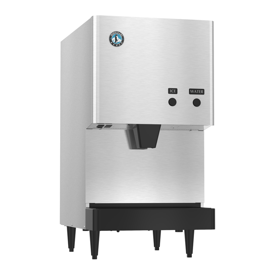
Page 5: General Information
II. General Information 1. Construction The Hoshizaki Cubelet Ice Dispenser, model DCM-270BAH-OS includes water supply, freezer, condensing, storage, dispensing and control assemblies. Note: *Adjustable Legs Minimum height - 4" Maximum height - 5.3" Do not adjust exceeding the above recommendation. -
Page 6: Operation - How It Works
2.Operation - How it works Water flows from the potable water source through the water supply line shut-off valve, enters at the water inlet fitting and into the water reservoir. The water reservoir functions to maintain a constant water level inside the freezer assembly. Water from the water reservoir enters at the bottom of the freezer. -
Page 7: Technical Information
III. Technical Information 1. Water Circuit and Refrigerant Circuit... -
Page 8: Performance Data
2. Performance Data [a] DCM-270BAH-OS (air-cooled) Note: Pressure data is recorded first 5 minutes in freezing cycle. The data without *marks should be used for reference. We reserve the right to make changes in specifications and design without prior notice. -
Page 9: Wiring Diagram
3. Wiring Diagram... -
Page 10: Sequence Of Electrical Circuit
4. Sequence of Electrical Circuit POWER ON WATER STARTS TO BE SUPPLIED TO RESERVOIR AGITATION TIMER ON - (2 SEC.) - Page 11 RESERVOIR FILLS UP GEAR MOTOR TURNS ON...
- Page 12 COMPRESSOR STARTS 60 SEC. AFTER GEAR MOTOR.
- Page 13 ICE MAKING CONTINUES. START CAPACITOR TAKEN OUT OF CIRCUIT...
- Page 14 BIN CONTROL TRIPS. COMPRESSOR STOPS 90 SECONDS LATER.
- Page 15 GEAR MOTOR STOPS 60 SECONDS AFTER COMPRESSOR.
- Page 16 DISPENSE ICE (BIN CONTROL STILL TRIPPED)
- Page 17 FLUSH SWITCH ACTIVATED.
- Page 18 FLUSH TIMER ACTIVATED.
- Page 19 AGITATION TIMER ACTIVATES GEAR MOTOR.
-
Page 20: Service Diagnosis
IV. Service Diagnosis 1. No Ice Production PROBLEM POSSIBLE CAUSE [1] The ice dispenser will a) Power Supply Cord not start. b) Power Switch (on left bottom of front panel) c) Fuse 1A (Control Box) Water valve operates, a) Water Supply Line but no ice is produced. - Page 21 PROBLEM POSSIBLE CAUSE Fan motor will not start. a) Fan Motor b) Timer No water or poor flow. a) Water Supply b) Water Valve c) Float Switch d) Water Control Relay e) Bin Control Switch f) Ice Making Switch Ice dispenser will not Float Switch stop even if out of water.
-
Page 22: Low Ice Production
1. Overload protector 1. Check condenser and fan stops compressor motor. intermittently. 1. Remove auger, use freezing cylinder. Hoshizaki "Scale Away" or "LIME-A-WAY" solution to clean periodically. If water is found to exceed the following levels, install a conditioner: Hardness 50 ppm Silica 30 ppm 1. -
Page 23: Faulty Dispenser
3. Faulty Dispenser PROBLEM POSSIBLE CAUSE No ice is dispensed. Storage Bin b) Agitator c) Solenoid d) Ice switch or dispensing sensor. e) Ice Dispensing Relay No water is dispensed. a) Water Valve (Dispensing) b) Water Dispensing Sensor [3] Ice keeps being a) Shutter dispensed. - Page 24 If you experience problems with the ice or water dispense, use the following charts along with the wiring diagram (section III, 3) to guide you through your troubleshooting. The following tables show the proper voltage readings for each operation. Ice Dispensing in Continuous Mode Lead 1 Lead 2 Dispense Non-Dispense...
-
Page 25: Other
4. Other PROBLEM POSSIBLE CAUSE Ice dispenser will not a) Bin Control Switch stop even if filled with ice. b) Water Control Relay c) Timer Reservoir overflows a) Water Supply (water will not stop). b) Water Valve c) Float Switch d) Water Control Relay A lot of water drains Mechanical Seal... -
Page 26: Removal And Replacement Of Components
V. Removal and Replacement of Components Ensure all components, fasteners and thumbscrews are securely in place after the equipment is serviced. 1. The Polyol Ester (POE) oils used in R-404A units can absorb moisture quickly. Therefore it is important to prevent moisture from entering the sys- tem when replacing or servicing parts. -
Page 27: Brazing
5) Disconnect the vacuum pump, and attach a refrigerant service cylinder to the high-side line. Remember to loosen the connection, and purge the air from the hose. See the nameplate for the required refrigerant charge. Hoshizaki recommends only virgin refrigerant or reclaimed refrigerant which meets ARI Standard No. 700-88 be used. -
Page 28: Removal And Replacement Of Compressor
3. Removal and Replacement of Compressor Always install a new drier every time the sealed refrigeration system is opened. Do not replace the drier until after all other repair or replacement has been made. Note: When replacing a compressor with a defective winding, be sure to install the new start capacitor and start relay supplied with the replacement compressor. -
Page 29: Removal And Replacement Of Drier
12) Braze the process, suction and discharge lines (do not change this order), while purging with nitrogen gas flowing at the pressure 3-4 PSIG. 13) Install the new filter drier. 14) Check for leaks using nitrogen gas (140 PSIG) and soap bubbles. 15) Connect the terminals, and replace the terminal cover in its correct position. -
Page 30: Removal And Replacement Of Thermostatic Expansion Valve
5. Removal and Replacement of Thermostatic Expansion Valve Sometimes moisture in the refrigerant circuit exceeds the drier capacity and freezes up at the expansion valve. Always install a new drier every time the sealed refrigeration system is opened. Do not replace the drier until after all other repair or replacement has been made. -
Page 31: Removal And Replacement Of Pressure Switch
14) Place the new expansion valve cover in position. 15) Replace the panels in their correct positions. 16) Plug in the dispenser and turn on the power supply. 6. Removal and Replacement of Pressure Switch Always install a new drier every time the sealed refrigeration system is opened. Do not replace the drier until after all other repair or replacement has been made. -
Page 32: Removal And Replacement Of Control Water Valve
7. Removal and Replacement of Control Water Valve 1) Unplug the icemaker. 2) Remove the panels. 3) Close the water supply line shut-off valve. 4) Disconnect the terminal from the control water valve. 5) Loosen the fitting nut on the control water valve inlets, and remove the control water valve. -
Page 33: Removal And Replacement Of Flush Water Valve
8. Removal and Replacement of Flush Water Valve 1) Turn off the power supply. 2) Remove the panels. 3) Close the water supply line shut-off valve. 4) Remove the clamp and disconnect the hose from the flush water valve that attaches to the evaporator. -
Page 34: Removal And Replacement Of Float Switch
9. Removal and Replacement of Float Switch 1. Fragile, handle very carefully. 2. If the float switch works poorly because of scale or other foreign matter, install a filter or softener in the water supply line. 1) Unplug the dispenser and turn off the power supply. 2) Close the water supply line shut-off valve. -
Page 35: Removal And Replacement Of Bin Control Switch Assembly
10. Removal and Replacement of Bin Control Switch Assembly 1) Turn off the power supply and unplug the dispenser. 2) Remove the top panel. 3) Remove the bin control switch from the storage bin cover. (Twist, then pull up.) 4) Cut the wire leads and remove switch. 5) Assemble the replacement switch, reversing the procedure used to remove the old switch. -
Page 36: Removal And Replacement Of Storage Bin Assembly
11. Removal and Replacement of Storage Bin Assembly 1) Move the ice making switch to the “FLUSH” position. 2) Press the push button to dispense ice and remove all ice from the storage bin. 3) Turn off the power supply and unplug the dispenser. 4) Remove the panels. -
Page 37: Removal And Replacement Of Agitator And Drip Ring
12. Removal and Replacement of Agitator and Drip Ring 1) Move the ice making switch to the “OFF” position. 2) Press the push button to dispense ice and remove all ice from the storage bin. 3) Turn off the power supply, and unplug the dispenser. 4) Remove the top panel. -
Page 38: Removal And Replacement Of Evaporator Assembly
13. Removal and Replacement of Evaporator Assembly 1) Move the ice making switch to the “OFF” position. 2) Press the push button to dispense ice and remove all ice from the storage bin. 3) Turn off the power supply, and unplug the dispenser. 4) Flush all water out of the system. - Page 39 13) Disconnect the brazing-connections of the expansion valve and the copper tube - low side from the evaporator, using brazing equipment. 14) Braze the new evaporator with nitrogen gas flowing at a pressure of 3-4 PSIG. 15) Replace the drier. 16) Check for leaks using nitrogen gas (140 PSIG) and soap bubbles.
- Page 40 28) Assemble the removed parts in the reverse order of which they were removed Be careful not to scratch the surface of the O-ring, or it may cause water leaks. Handle the mechanical seal with care not to scratch nor to contaminate its contact surface.
-
Page 41: Cleaning And Maintenance Instructions
VI. Cleaning and Maintenance Instructions Ensure all components, fasteners and thumbscrews are securely in place after any maintenance or cleaning is done to the equipment. 1. Preparing the Ice Dispenser for Long Storage When shutting off the ice dispenser for an extended time, drain out all water from the water line and remove the ice from the storage bin. -
Page 42: Cleaning Instructions
[a] Cleaning Procedure 1) Close the water supply line shut-off valve. 2) Dilute approximately 6 fl. oz. of recommended cleaner Hoshizaki “Scale Away” or “LIME-A-WAY” (manufactured by Economics Laboratory, Inc.) with 1 gal. of water. 3) Move the ice making switch, located on the control box, to the “FLUSH” position. - Page 43 Fig. 4 Fig. 5...
- Page 44 12) Replace the drip ring and agitator. 13) Move the ice making switch and then the power switch to the “ON” position. Place the storage bin cover in position, and start the automatic icemaking process. Run the ice dispenser until it stops automatically. 14) Move the ice making switch to the “FLUSH”...
-
Page 45: [B] Sanitizing Procedure
[b] Sanitizing Procedure 1) Dilute approximately 1.5 fl. oz. of a 5.25% sodium hypochlorite solution (chlorine bleach) with 3 gal. of water. 2) Pour the sanitizing solution carefully into the reservoir through the opening in the center of the storage bin up to an overflow level. 3) Wait for 10 minutes to start the icemaking process. -
Page 46: Maintenance Instructions
2. Maintenance Instructions This ice dispenser must be maintained individually, referring to the instruction manual and labels provided with the ice dispenser. 1) Stainless Steel Exterior To prevent corrosion, wipe the exterior occasionally with a clean and soft cloth. Use a damp cloth containing a neutral cleaner to wipe off oil or dirt build up.