Advertisement
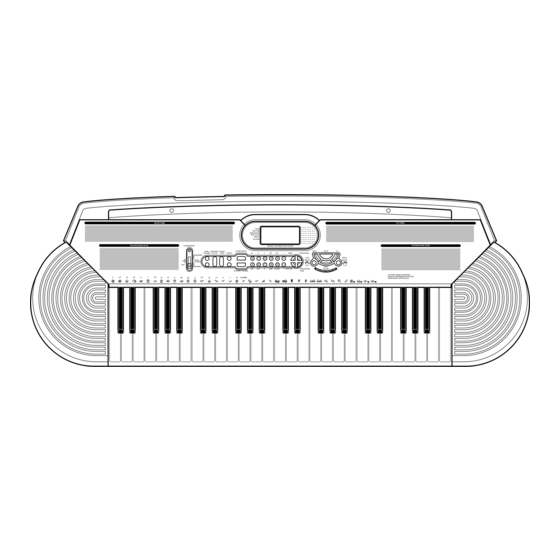
CTK-401
100 RHYTHMS
100 SONG BANK (00-49)
POWER/MODE
MAIN
SYNCHRO/
START/
VOLUME
FILL-IN
STOP
TEMPO
FINGERED
CASIO
ON
CHORD
OFF
NORMAL
ELECTRONIC KEYBOARD
TONE
RHYTHM
SONG BANK
STATUS
TEMPO
VOLUME
MUSICAL INFORMATION SYSTEM
CHORD BOOK
REW
STOP
M
m
7
M7
dim
TONE
SONG BANK
0
1
2
3
4
LEFT
ON/OFF
5
6
7
8
9
PLAY/
TRANSPOSE/
aug
sus4
-5
add9
CLEAR
RHYTHM
PAUSE
ACCOMP VOLUME
TUNE
C
100 TONES
100 SONG BANK (50-99)
FF
RIGHT
ON/OFF
100 SONG BANK KEYBOARD
MUSICAL INFORMATION SYSTEM
SONG BANK CONTROLLER
CTK-401
Advertisement
Table of Contents

Related Manuals for Casio CTK-401


Summary of Contents for Casio CTK-401
- Page 1 CTK-401 100 RHYTHMS 100 TONES TONE RHYTHM SONG BANK STATUS TEMPO VOLUME 100 SONG BANK (00-49) 100 SONG BANK (50-99) POWER/MODE MUSICAL INFORMATION SYSTEM MAIN SYNCHRO/ START/ CHORD BOOK STOP VOLUME FILL-IN STOP TEMPO TONE SONG BANK FINGERED LEFT RIGHT...
-
Page 2: Table Of Contents
CONTENTS Specifications ........................... 1 Block Diagram ..........................2 Circuit Description ..........................3 Adjustment ............................7 Major Waveforms ..........................8 Printed Circuit Boards ........................9 Schematic Diagrams ........................11 Exploded View ..........................15 Parts List ............................17... -
Page 3: Specifications
12 notes maximum (6 for certain tones) Auto accompaniment Rhythm patterns: Tempo: Variable (236 steps, = 20 to 255) Chords: 2 fingering methods (CASIO CHORD, FINGERED) Rhythm controller: START/STOP, SYNCHRO/FILL-IN Accomp volume: 0 to 9 (10 steps) Song bank Tunes:... -
Page 4: Block Diagram
BLOCK DIAGRAM COM1 ~ COM16 LCD Driver SED1278F0A LSI3 Buttons Keyboard SEG1 ~ SEG40 KO8 ~ KI0 ~ KI6 DB4 ~ DB7 Output KO12 Filter (L) Q104 Power Amp. KO0 ~ KO7 TA8248K IC101 Filter (R) Q105 MSM 6755B-17 MD0 ~ MD7 LSI1 VCC DVDD ROM(2M-bit) -
Page 5: Circuit Description
Down Start/ Synchro/ Chord Accomp Stop Fill-in Book Volume Transpose/ Song KO10 Rhythm Tone Tune Bank CASIO KO11 Fingered Normal Power Off Chord Play/ KO12 Right Stop Left Rewind Pause NOMENCLATURE OF KEYS C#2 D#2 F#2 G#2 A#2 C#3 D#3... - Page 6 CPU (LSI1: MSM6755B-17) The CPU reads sound data from the ROM in accordance with the pressed key and the selected tone; the CPU can read rhythm data simultaneously when a rhythm pattern is selected. Then it provides the left and the right channels’...
- Page 7 Pin No. Terminal In/Out Function 74 ~ 77 DB4 ~ DB7 Data bus for the LCD driver — Not used LVCC +5 V source 80 ~ 84 KO8 ~ KO12 Terminals for button scan signal 85 ~ 87 P65 ~ P67 —...
- Page 8 FILTER BLOCK Since the sound signals from the CPU is stepped waveforms, the filter block is added to smooth the waveforms. Amp. Filter TA8248K Block MSM6755B-17 POWER AMPLIFIER (IC101: TA8248K) The power amplifier is a two-channel amplifier with standby switch. The following table shows the pin function of IC101.
-
Page 9: Adjustment
ADJUSTMENT MAIN PCB 1) Items to be adjusted: Item Measuring Instrument Vop voltage setting Voltmeter 2) Adjustment and Test Point Locations (TOP VIEW) Test point 3) Equipment connection/Procedure Vop voltage setting Voltmeter Output Input Input Input Output Output Adjust for Adjust Connection Point... -
Page 10: Major Waveforms
MAJOR WAVEFORMS 1 Clock pulse 2 +5 V source DVDD MSM6755B-17 pin 32 JC connector pin 6 3 APO signal JC connector pin 5 6 Button scan signal KO6 4 Sound waveform (R-ch) Tone: Whistle JA connector pin 14 JC connector pin 4 Key: 7 Button scan signal KO7 5 Sound waveform (L-ch) Volume:... -
Page 11: Printed Circuit Boards
PRINTED CIRCUIT BOARDS Main PCB JCM442-MA1M Top View Bottom View — 9 —... -
Page 12: Schematic Diagrams
SCHEMATIC DIAGRAMS Main PCB JCM442-MA1M — 11 —... - Page 13 Sub PCB JCM442-MA2M — 12 —...
- Page 14 Keyboard PCBs KDM4910K-KY1M/KY2M — 13 —...
- Page 15 Common Segment — 14 —...
-
Page 16: Exploded View
EXPLODED VIEW — 15 —... -
Page 17: Parts List
PARTS LIST CTK-401 Notes: This parts list does not include the cosmetic parts, which parts are marked with item No. "R-X" in the exploded view. Contact our spare parts department if you need these parts for refurbish. Prices and specifications are subject to change with- out prior notice. - Page 18 Item Code No. Parts Name Specification Main PCB 6926 0200 PCB/ASS'Y (MA1M) M240592*1 LSI1 2012 5603 LSI/MC (CPU) MSM6755B-17 LSI2 2012 5611 LSI/MASK-ROM UM23C2101M-7384/Q LSI3 2012 5569 LSI/LCD DRIVER SED1278F0A 2012 1883 IC/MOS (RESET IC) RN5VD40AA-TR 2252 1239 TRANSISTOR 2SC4081T106Q 2775 3286 POTENTIOMETER EVM3SSX50B53 2590 2100 OSCILLATOR/CERAMIC...
- Page 19 MA0600571A...
Need help?
Do you have a question about the CTK-401 and is the answer not in the manual?
Questions and answers
Не звучат клавиши первой октавы