Table of Contents
Advertisement
AUDIO VIDEO
CONTROL RECEIVER
MODEL TX-DS696
STANDBY/ON
STANDBY
POWER
ON
OFF
DISPLAY
DIMMER
FM MODE
PRESET MEMORY
PHONES
AUDIO
DVD
VIDEO
1
VIDEO
2
VIDEO
3
SELECTOR
1
2
VCR
VCR
Black, Golden and Silver models
BMDD
120V AC, 60Hz
BMPP,SMPP
230-240V AC, 50Hz
BMPA,GMPA
BMWT,GMWT
220-230V/120V AC,
GMWR
50/60 Hz
SAFETY-RELATED COMPONENT WARNING!!
COMPONENTS IDENTIFIED BY MARK
SCHEMATIC DIAGRAM AND IN THE PARTS LIST ARE
CRITICAL FOR RISK OF FIRE AND ELECTRIC SHOCK.
REPLACE THESE COMPONENTS WITH ONKYO
PARTS WHOSE PART NUMBER APPEAR AS SHOWN
IN THIS MANUAL.
MAKE LEAKAGE CURRENT OR RESISTANCE
MEASUREMENTS TO DETERMINE THAT EXPOSED
PARTS ARE ACCEPTABLY INSULATED FROM THE
SUPPLY CIRCUIT BEFORE RETURNING THE
APPLIANCE TO THE CUSTOMER.
SERVICE MANUAL
2
2
REC OUT
ZONE
ZONE
LEVEL CH LEVEL
MASTER VOLUME
DSP / MODE ADJ
SETUP
RETURN
PUSH TO ENTER
TUNING
PRESET
SMART SCAN NAVIGATOR
BASS
TREBLE
VIDEO
4
TAPE
FM
AM
PHONO
C D
TX-DS
696
AV RECEIVER
!
ON THE
AUDIO VIDEO
CONTROL RECEIVER
MODEL TX-DS595
STANDBY/ON
STANDBY
POWER
ON
OFF
DISPLAY
RT / PTY/ TP
FM MODE
PRESET MEMORY
TUNING
PHONES
AUDIO
SELECTOR
DVD
VIDEO
1
VIDEO
2
VIDEO
3
VCR
Black, Golden and Silver models
BMDD
120V AC, 60Hz
BMPP,SMPP
230-240V AC, 50Hz
BMPA,GMPA
BMWT,GMWT
220-230V/120V AC,
GMWR
50/60 Hz
GMGT
220-230V AC,50 Hz
TABLE OF CONTENTS
Specifications TX-DS595
Specifications TX-DS696
Service procedures
Panel views TX-DS595
Panel views TX-DS696
IC block diagrams and descriptions
Microprocessor TX-DS595
Main microprocessor
Sub microprocessor
Microprocessor TX-DS696
Main microprocessor
Sub microprocessor
About debug mode
FL tube view
Printed circuit board-parts list TX-DS595
Printed cirucit board-parts list TX-DS696
Wiring view TX-DS595
Block diagram TX-DS595
Wirng view TX-DS696
Block diagram TX-DS696
Schematic diagrams & PC board views
Input section TX-DS595
Input section TX-DS696
Power amplifier section 1
Power amplifier section 2
Display section TX-DS595
Display section TX-DS696
Video section TX-DS595
Video section TX-DS696
DSP section
Adjustments and confirmation procedures
Exploded view & Parts list TX-DS595
Exploded view & Parts list TX-DS696
Packing view TX-DS595
Packing view TX-DS696
TX-DS595/696
Ref. No. 3678
042001
A
SPEAKERS
B
CH LEVEL
MASTER VOLUME
SETUP
DSP / MODE ADJ
RETURN
PUSH TO ENTER
PRESET
SMART SCAN NAVIGATOR
BASS
TREBLE
TAPE
FM
AM
PHONO
C D
AV RECEIVER
TX-DS
595
2
3
4
5
8
11
20
20
22
24
24
26
27
28
29
34
39
41
43
45
47
47
51
55
59
63
67
71
75
81
87
89
93
97
98
Advertisement
Table of Contents

Related Manuals for Onkyo TX-DS696


Summary of Contents for Onkyo TX-DS696
- Page 1 Power amplifier section 2 Display section TX-DS595 Display section TX-DS696 Video section TX-DS595 Video section TX-DS696 DSP section Adjustments and confirmation procedures Exploded view & Parts list TX-DS595 Exploded view & Parts list TX-DS696 Packing view TX-DS595 Packing view TX-DS696...
-
Page 2: Specifications
TX-DS595 SPECIFICATIONS AMPLIFIER SECTION TUNER SECTION Continuous Average Power output (FTC) All channels: 75 W per channel min. RMS at 8 Tuning Range: 87.5 to 108.0 MHz (50-kHz steps) ohm , 2 channels driven from 20Hz Usable Sensitivity to 20 kHz with no more than Mono: 11.2 dBf, 1.0 µV (75 ohm IHF) 0.08% total harmonic distortion. - Page 3 TX-DS696 SPECIFICATIONS AMPLIFIER SECTION TUNER SECTION Continuous Average Power output (FTC) All channels: 100 W per channel min. RMS at 8 Tuning Range: 87.5 to 108.0 MHz (50-kHz steps) ohm , 2 channels driven from 20Hz Usable Sensitivity to 20 kHz with no more than Mono: 11.2 dBf, 1.0 µV (75 ohm IHF)
-
Page 4: Service Procedures
Ce darnier est la qu le present symbol est controller to display "AM FREQ STEP?". appse. 3.Press the jog dial or ENTER button on the remote controller. TX-DS696 The currently set frequency step appears. CIRCUIT NO. PART NO. -
Page 5: Panel Views
TX-DS595 PANEL VIEWS SMART SCAN NAVIGATOR jog dial and indicators Front panel POWER switch Used to make settings in the setup display, change listening mode See illustration below settings, and more. Turns on and off the main power supply for the TX-DS595. STANDBY indicator SETUP button Press to enter and exit the setup mode. -
Page 6: Remote Controller
Press to enter and exit the setup mode. subtitle languages recorded on a DVD-Video. ENTER/cursor button CD/TAPE/DVD/MD operation buttons For selecting and entering settings in the setup mode. For operating Onkyo components connected to the TX-DS595. button INPUT SELECTOR buttons For adjusting the volume. - Page 7 TX-DS595 CONNECTION : Signal flow Analog audio output L (White) MONITOR VIDEO 1 VIDEO 2 VIDEO 3 Video output Video output VIDEO VIDEO S video R (Red) S video output REMOTE 4. DVD player CONTROL S VIDEO S VIDEO (DVD) TAPE L (White) 2.
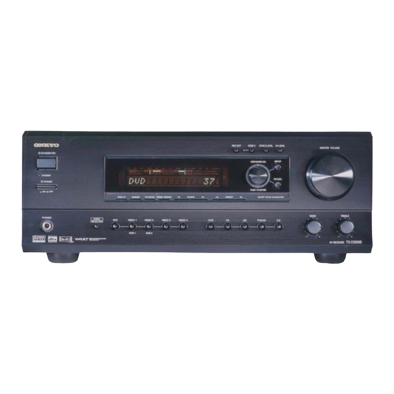
- Page 8 TV monitor as well as the front display on the TX-DS696. DSP / MODE ADJ SETUP Press to turn on the TX-DS696 when in the standby state. Press again to return the TX-DS696 to the standby state. STANDBY RETURN button...
- Page 9 ZONE 2: When in the RCVR mode, press this button to perform or sent by the remote controller. It also warns the user when an error Same as the input selector buttons on front panel of the TX-DS696. operations on the remote zone (Zone 2).
- Page 10 TX-DS696 CONNECTIONS Connecting your video Connecting antennas components [14, 15] Connect to devices with Cautions regarding the AC terminals Connecting speakers OUTLETS connectors COMPONENT VIDEO FRONT CENTER SURROUND ANTENNA SPEAKERS SPEAKER SPEAKERS Component video output Component video output COMPONENT VIDEO...
- Page 11 TX-DS595/696 IC BLOCK DIAGRAMS AND DESCRIPTIONS AK4112AVF(24-bit 96-kHz DIR) DVDD CM0/CDTO AVSS AVDD MCKO1 MCKO2 DVSS CM1/CDTI OCKS1/CCLK TVDD Clock Clock X'tal OCKS0/CSN V/TX Input Recovery Generator Oscillator MCKO1 Selector MCKO2 96kHz View FS96 DAUX Detect BICK V/TX DAUX AVDD SDTO DAIF LRCK...
- Page 12 TX-DS595/696 AK4527VQ(24bit 96kHz 6-ch. CODEC) PIN/FUNCTION No. Pin Name I/O Function SDOS SDTO Source Select Pin (Note 1) Audio LIN+ "L" : Internal ADC output, "H" : DAUX input LIN- Control Mode Select Pin This pin should be connected to DVSS. RIN+ SMUTE Soft Mute Pin...
-
Page 13: Block Diagram
TX-DS595/696 BA7625(Video Select Switch) MONITOR OUT CTLA VOUT1 LOGIC VOUT1 CTRE CTLB LOGIC VOUT2 VOUT2 CTLD CTLC X:Don't care NJM2296D(Dual Video 6dB Amplifier with 75ohm Driver)) 75 ohm 6.2 dB V out 2 Driver AMP. 750ohm 2 V 2.2kohm 2.0kohm SAG correction 75 ohm 6.2 dB V out 2 Driver AMP. 750ohm 2 V ... - Page 14 TX-DS595/696 CS49326-CL(DIR) A0,SCCLK AUDATA2 DATA7,EMAD7,GPIO7 DC-Reserved DATA6,EMAD6,GPIO6 DD-Reserved DATA5,EMAD5,GPIO5 RESET DATA4,EMAD4,GPIO4 AGND DGND2 FILT1 DATA3,EMAD3,GPIO3 FILT2 DATA2,EMAD2,GPIO2 CLKSEL DATA1,EMAD1,GPIO1 CLKIN DATA0,EMAD0,GPIO0 CMPREQ,LRCLKN2 SCDIO, DATA7:0, R/W, SCDOUT, EMAD7:0, EMOE, EMWR, PSEL, ABOOT, EXTMEM, GPIO7:0 GPIO11 GPIO10 GPIO9 RESET SCCLK SCDIN INTREQ GPIO8 CMPDAT, SDATAN2...
- Page 15 TX-DS595 – 15 –...
- Page 16 TX-DS595/696 TC74VHC541FT(Octal bus buffer) INPUTS OUTPUT X :Don't care Z :High impedance...
- Page 17 TX-DS595/696 TC9162AF(Analog Switch) TC9163AF(Analog Switch) COM1 COM1 COM1 COM1 COM2 COM2 COM2 COM2 COM3 COM3 COM3 COM4 COM4 COM3 DATA DATA SHIFT REGISTER SHIFT REGISTER Pin No. Symbol Function Symbol Pin No. Function Negative power supply Negative power supply Ground Ground Positive power supply Positive power supply...
- Page 18 TX-DS595/696 TC9164AF(Analog Switch) TC9274N(Analog Switch Array) COM1 COM1 COM2 COM2 COM3 COM3 DATA SHIFT REGISTER Symbol Pin No. Function Negative power supply Ground Positive power supply LEVEL SHI FT AND 2,3,4,6,7,8,10,11 S1~S8 Input/output terminals SHI FT REGI STER 27,26,25,23,22,21,19,18 S1~S8 Input/output terminals 5,9,12 COM1 ~ COM3...
- Page 19 TX-DS595/696 TC9482N(6 channel electronic volume) TEST L-OUTA R-OUT A L-INA R-INA latch latch L-A-GNDA R-A-GNDA R-OUTB L-OUTB L-INB R-INB 3 to 7 Same as L-ch decoder Circuit latch 4 to 13 decoder latch R-A-GNDB L-A-GNDB L-OUTC R-OUTC L-INC R-INC latch R-A-GNDC latch L-A-GNDC...
-
Page 20: Main Microprocessor Terminal Descriptions
TX-DS595 MAIN MICROPROCESSOR TERMINAL DESCRIPTIONS Pin No. Symbol Descriptions Pin No. Symbol Descriptions AMUT Audio muting output pin. RLED Right direction LED control output pin of SSC. Output B pin to control video signal. ~SBMRST Reset signal output pin to sub microprocessor. Output A pin to control video signal. -
Page 21: Sub Microprocessor Terminal Descriptions
TX-DS595/696 SUB MICROPROCESSOR TERMINAL DESCRIPTIONS Pin No. Symbol Description Pin No. Symbol Description Power supply terminal. Connect to 5V. Segment output terminal of P22. Ground terminal. Segment output terminal of P21. Ceramic oscillator connection terminals for main system. Segment output terminal of P20. Connect the 5MHz ceramic oscillator between #3 and #4. -
Page 22: Main Microprocessor
TX-DS696 MAIN MICROPROCESSOR Q701 Q801 P184 RS232C Q751 Q752 GAIN GAIN MUTE MUTE IC74VHC541FT CODEC CONTROL CONTROL IC74HCI7007AF CS493002CL AK4527VO Q418 Q417 Q181 BUFFER MUTING POWER SURROUND Q224 VIDEO CONTOROL Q433 TC9164AF Q151 Q2005 AK4112AW CENTER SP LC74761-9189 -232CTS VOLDA... - Page 23 TX-DS696 MAIN MICROPROCESSOR TERMINAL DESCRIPTIONS Pin No. Symbol Descriptions Pin No. Symbol Descriptions DSPDA Serial data output pin to DSP IC. BVDD Power supply pin. Connect to +5V. DSPCL Serial clock output pin to OSD IC. BVSS Ground pin. AMUT Audio muting output pin.
-
Page 24: Sub Microprocessor
TX-DS696 SUB MICROPROCESSOR OPERATION KEY RETURN SET UP RECOUT ZONE 2 CH LEVEL Z2 VOL DIMMER TAPE PHONO STANDBY VIDEO 1 VIDEO 2 VIDEO 3 VIDEO 4 AUDIO SEL < > < > DISPLAY FM MODE MEMORY TUNING TUNING PRESET... -
Page 25: About Debug Mode
TX-DS595/696 ABOUT DEBUG MODE TX-DS595 TX-DS696 SPEAKERS SLEEP MPEG DS P FM MUTE STEREO TUNED AUTO PC M DIGITAL FM STEREO MEMORY DIRECT STANDBY 1. How to enter the debug mode 8. Judgment of DSP input signal Press and hold down the AUDIO SEL button, then press It displays the result of detection about the input signal the STANDBY/ON button to display "DEBUG MODE IN". -
Page 26: Fl Tube View
TX-DS595/696 FL TUBE VIEW 15-BT-64GNK(Model TX-DS595) SPEAKERS SLEEP MPEG DS P STEREO TUNED FM MUTE AUTO PC M DIGITAL DIRECT FM STEREO MEMORY STANDBY 14G 13G 12G 11G 10G 3G 2G SPEAKERS SLEEP MPEG DS P STEREO TUNED AUTO DIRECT FM MUTE STANDBY MEMORY... -
Page 27: Printed Circuit Board Parts List
TX-DS595 PRINTED CIRCUIT BOARD PARTS LIST DSP CIRCUIT PC BOARD (NADG-7066-1H/1I/1J/1K) CIRCUIT NO. PART NO. DESCRIPTION CIRCUIT NO. PART NO. DESCRIPTION Capacitors C808 356742209R2 22 F,16V,Elect. Q101,Q102 22241383R2, NJM4565M-D, C809 356724709R2 47 F,6.3V,Elect. Q405-Q409 22240489R1NE or MPC4570G2-T1(MST) or C831-C836 356741009R2 10 F,16V,Elect. - Page 28 TX-DS595 PRINTED CIRCUIT BOARD PARTS LIST CIRCUIT NO. PART NO. DESCRIPTION CIRCUIT NO. PART NO. DESCRIPTION Sockets Capacitors P6000A-P6004A 25052287 NSCT-4P2184 C901 3500196S RE275V-103M,.IS P6011A 25052295 NSCT-12P2192 C902 3300030 DE1307E472M-KH,IS Plug C922 354762219 220 F,35V,Elect. P404A 25055154 NPLG-10P138 Resistors R901 431533355 3.3Mohm,1/2W,Solid <D>...
- Page 29 TX-DS595 PRINTED CIRCUIT BOARD PARTS LIST CAUTION: Replacement for transistor of mark *, if necessary must be made from the same beta group (H ) as the original type. POWER AMPLIFIER B PC BOARD (NAAF-7077-1H/1I) CIRCUIT NO. PART NO. DESCRIPTION CIRCUIT NO.
- Page 30 TX-DS595 PRINTED CIRCUIT BOARD PARTS LIST CIRCUIT NO. PART NO. DESCRIPTION CIRCUIT NO. PART NO. DESCRIPTION Capacitors Diodes C9508 354744729S 4700 F,16V,Elect. D7001,D7002 223234R2 or 1SS352 or C9510 354772219 220 F,63V,Elect. D7004-D7006 223269R2 1SS355 Resistors D7003 224490820R2 UDZ8.2B R6907 453532294 0.22ohm+/-5%,1/2W,Metal D7007 224490510R2...
- Page 31 TX-DS595 PRINTED CIRCUIT BOARD PARTS LIST CIRCUIT NO. PART NO. DESCRIPTION COMPOSITE VIDEO TERMINAL PC BOARD (NAVD-7096-1H/1I) Oscillator CIRCUIT NO. PART NO. DESCRIPTION X1001 3010203 or AF6146CG or 3010345 HQS-3H2-04332-20 <P> Q261 22240373 BA7625 Capacitors Transistors C1003,C1007 354721019 100 F,6.3V,Elect. <P> Q262,Q264 2214375R2 or 2SA1162-GR or...
- Page 32 TX-DS696 PRINTED CIRCUIT BOARD PARTS LIST DSP CIRCUIT PC BOARD (NADG-7066-1A/1B/1C/1D) CIRCUIT NO. PART NO. DESCRIPTION CIRCUIT NO. PART NO. DESCRIPTION Terminals P121 25045645 NPJ-2PDO450 Q101,Q102 22241383R2, NJM4565M-D, P401 25045572 NPJ-6PDBRW387 Q405-Q409 22240489R1NE or MPC4570G2-T1(MST) or P407 25045567 NPJ-1PDBL382 Q802-Q804...
- Page 33 TX-DS696 PRINTED CIRCUIT BOARD PARTS LIST TERMINAL PC BOARD (NAETC-7069-1A/1B/1C/1D/1E) CIRCUIT NO. PART NO. DESCRIPTION CIRCUIT NO. PART NO. DESCRIPTION Outlet P902 25051125 ! NSCT-4P912 <P/WT> Q6931 222780565JRC NJM78M56FA 25051126 ! NSCT-4P913 <D> Transistors 25052115 ! NSCT-2P2013 <A> Q5303,Q5307 2215864,...
- Page 34 TX-DS696 PRINTED CIRCUIT BOARD PARTS LIST CIRCUIT NO. PART NO. DESCRIPTION CIRCUIT NO. PART NO. DESCRIPTION Transistors Terminal Q6070-Q6074 2214984 or 2SC2631-R or P6801 25045572 NPJ-6PDBRW387 2214985 2SC2631-S Sockets Q6600-Q6602 2215864, KTC3199-GR, JL6803A,JL6804A 25051109 NSCT-5P896 Q6701,Q6702 2212115, 2SC2458-GR, JL6951A,JL6952A 25051109...
- Page 35 TX-DS696 PRINTED CIRCUIT BOARD PARTS LIST CIRCUIT NO. PART NO. DESCRIPTION VOLUME PC BOARD (NASW-7085-1A/1B/1C/1D) Sockets CIRCUIT NO. PART NO. DESCRIPTION JL6402A 25051088 NSCT-4P875 P7004B 25051087 NSCT-3P874,Socket JL9501B 25051095 NSCT-11P882 S7001 25065575 EC16B2425,Rotary encoder P6411A 25051529 NSCT-18P1316 Plug HEDPHONE TERMINAL PC BOARD (NAETC-7086-1A/1B/1C/1D)
- Page 36 TX-DS696 PRINTED CIRCUIT BOARD PARTS LIST CIRCUIT NO. PART NO. DESCRIPTION S VIDEO TERMINAL PC BOARD (NAVD-7090-1A/1B) Capacitors CIRCUIT NO. PART NO. DESCRIPTION C2032 374726824 6800pF+/-5%,50V,Plastic C2034,C2036 354724719 470 F,6.3V,Elect. Q212,Q213 22240373 BA7625 C2035 354780229 2.2 F,50V,Elect. Q224 22241221R2 TC9164AF...
-
Page 37: Wiring View
TX-DS595 WIRING VIEW The bracket < > shows the page of schematic diagram. P1001A NAAF-7097 P6805A NAPS-7070 <P62> P911 NAVD-7095 P403A P205A P311A NAETC-7072 P901A <P49,P50> <P61> tuner <P71> P918 P912 P913 P917 JL6803B JL6804B JL201B <P65> NAETC-7071 P931A NAETC-7087 <P62>... - Page 39 TX-DS696 WIRING VIEW The bracket < > shows the page of schematic diagram. P1001A P6805A NAPS-7070 <P62> P911 P403A P205A P311A NAETC-7072 NAAF-7093 P901A <P61> tuner P918 <P79> P912 P913 P917 NAVD-7090 <P53,P54> JL6803B JL6804B <P69> NAETC-7071 P931A NAETC-7087 <P62>...
- Page 62 Press and hold down DVD button, then press STANDBY button. During "TEST-1" on the FL tube light on, press ZONE 2 (TX-DS696) or SPEAKER A (TX-DS595) button. Apply DC 1.5 to 3V to MULTI CHANNEL INPUT terminal with no load.
-
Page 63: Test Mode
Note: VIDEO 1:TEST-1 VIDEO 2 :TEST-2 ZONE2/SP A: UP VIDEO 3 :TEST-3 VIDEO 4:TEST-4 REC OUT/SP B: DOWN Test mode of FL tube Test-X YZ TX-DS696: Press ZONE 2 or REC OUT button to change the test mode of FL tube. TX-DS595:Press SPEAKER A or SPEAKER B button FL TUBE to change the test mode of FL tube. -
Page 64: Exploded View
TX-DS595 EXPLODED VIEW P1001 P901 P412 P7002 F902 F901 U4 F903 T901 Q6050 Q6060 P800 F9501 F6901 F6902 Q6062 P650 Q6063... -
Page 65: Parts List
TX-DS595 PARTS LIST REF.NO. PART NO. DESCRIPTION REF.NO. PART NO. DESCRIPTION 27111192 Front bracket <B> 838430088 3TTB+8B(BC), Self-tapping screw 27111193 Front bracket <S> 27215345 Decorative frame <B> <D/WT/A> 27111194 Front bracket <G> 27215346 Decorative frame <B> <P> 29110157 Tape, copper 27215347 Decorative frame <S>... - Page 66 TX-DS595 PARTS LIST REF.NO. PART NO. DESCRIPTION REF.NO. PART NO. DESCRIPTION 1A896597-1H NAAF-7097-1H, Input terminal 1A896570-1H NAPS-7070-1H,Primary circuit PC board ass'y <D> PC board ass'y<D> 1A896570-1I NAPS-7070-1I,Primary circuit PC board ass'y <P> 1A896597-1I NAAF-7097-1I, Input terminal 1A896570-1J NAPS-7070-1J,Primary circuit PC board ass'y <WT> PC board ass'y<P/WT/WR/A/GT>...
- Page 67 TX-DS696 P1001 EXPLODED VIEW P901 P206 P412 P7002 F902 F901 U4 F903 T901 Q6050 Q6060 P800 F9501 F6901 F6902 Q6062 P650 Q6063...
- Page 68 TX-DS696 PARTS LIST REF.NO. PART NO. DESCRIPTION REF.NO. PART NO. DESCRIPTION 27111192 Front bracket <B> 28198778 Facet 27111193 Front bracket <S> 28135244 Badge <B> 27111194 Front bracket <G> 28135245 Badge <G/S> 29110157 Tape, copper 838430088 3TTB+8B(BC), Self-tapping screw 27141756 Retainer HP 27215345 Decorative frame <B>...
- Page 69 TX-DS696 PARTS LIST REF.NO. PART NO. DESCRIPTION CAUTION: Replacement for transistor of mark *, if necessary 1A896572-1A NAETC-7072-1A,Speaker terminal B PC board ass'y <D> must be made from the same beta group (H ) as 1A896572-1B NAETC-7072-1B,Speaker terminal B PC board ass'y <P>...
-
Page 70: Packing View
TX-DS595 PACKING VIEW Bottom P/WT/WR/GT/A (Accessories) P/WT/WR/GT/A (Printed matters) D(Printed matters and Accessories) NOTE: <B>:Black model only <S>: Silver model only <G>: Golden model only <D>: 120 V model only <P>: European model only <WT>: Worldwide model only <A>: Australian model only <WR>: Chinese model only <GT>: 220-230V model only PARTS LIST... - Page 71 Sales & Product Planning Div. : 2-1, Nisshin-cho, Neyagawa-shi, OSAKA 572-8540, JAPAN Tel: 072-831-8111 Fax: 072-833-5222 ONKYO U.S.A. CORPORATION 18 Park Way, Upper Saddle River, NJ 07458, U.S.A. Tel: 201-785-2600 Fax: 201-758-2650 E-mail: onkyo@onkyousa.com ONKYO EUROPE ELECTRONICS GmbH Industriestrasse 20, 82110 Germering, GERMANY Tel: 089-849-320 Fax: 089-849-3265 E-mail: info@onkyo.de...
Need help?
Do you have a question about the TX-DS696 and is the answer not in the manual?
Questions and answers