Sanyo PLC-XF45 Service Manual
Hide thumbs
Also See for PLC-XF45:
- Owner's manual (56 pages) ,
- Specifications (1 page) ,
- Dimensional drawing (1 page)
Table of Contents
Advertisement
SERVICE MANUAL
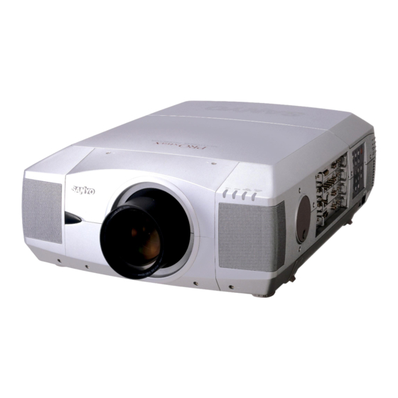
Multimedia Projector
PWB parts location diagrams
PRODUCT CODE :
MW8A
1 122 15100
MODEL NO.
(Projection lens is optional.)
CONTENTS ;
P1~P6
FILE NO.
PLC-XF45
U.S.A., Canada, Europe, Asia, Africa, M.E., U.K.
Chassis No. MW8-XF4500
NOTE: Match the Chassis No. on the rating
sheet on the cabinet with the
Chassis No. in the Service Manual.
If the Original Version Service
Manual Chassis No. does not
match the unites, additional
Service Literature is required. You
must refer to "Notices" to the
Original Service Manual prior to
servicing the unit.
Give complete "CHASSIS NO." for
parts order or servicing, it is shown on
the rating sheet on the cabinet of the
Projector.
2
3
4
6
10
15
26
40
42
49
59
63
65
70
78
79
REFERENCE NO. SM5110433
Advertisement
Table of Contents

Related Manuals for Sanyo PLC-XF45


Summary of Contents for Sanyo PLC-XF45
-
Page 1: Table Of Contents
FILE NO. SERVICE MANUAL PLC-XF45 MODEL NO. U.S.A., Canada, Europe, Asia, Africa, M.E., U.K. Multimedia Projector Chassis No. MW8-XF4500 NOTE: Match the Chassis No. on the rating sheet on the cabinet with the Chassis No. in the Service Manual. If the Original Version Service Manual Chassis No. -
Page 2: Specifications
TECHNICAL SPECIFICATIONS Projector Type Multi-media Projector Dimensions 22.9" x 10" x 30.9" (581 mm x 252 mm x 783 mm) (W x H x D) Net Weight 81.7 lbs (37 kg) LCD Panel System 1.8" TFT Active Matrix type, 3 panels Panel Resolution 1024 x 768 dots Number of Pixels... -
Page 3: Safety Instructions
Safety Instructions SAFETY PRECAUTIONS PRODUCT SAFETY NOTICE WARNING: The chassis of this projector is isolated (COLD) from Product safety should be considered when a compo- AC line by using the converter transformer. Primary nent replacement is made in any area of the projec- side of the converter and lamp power supply unit cir- tor. -
Page 4: Protections
Protections This projector is equipped with the following protec- tions to operate in safety. Fuse for circuit protection The fuse is located in the rear inside a projector. (Refer to figure.) When either the LAMP indicator or the READY indicator is not illuminated, fuse may be opened. -
Page 5: Overheating Protection
Overheating Protection The temperature monitor system -- The temperature monitor system is provided to prevents damage of optical components (the LCD panel and polarization film etc.) inside a projector from overheat. Two protection systems are provided. Each system operation as follows ; ----- The temperature monitor -1: ----- ----- The temperature monitor -2 : ----- (Temperature check of lamps. -
Page 6: Ass'y Lamp Replacement
LAMP REPLACEMENT Before Replacement This Projector is equipped with 4 Projection Lamps to ensure brighter image and those lamps are controlled by Lamp Management Function. Lamp Management Function detects status of all lamps and shows status on screen or on LAMP REPLACE indicator. -
Page 7: Lamp Replacement
LAMP REPLACEMENT CAUTION CAUTION For continued safety, replace with a lamp Do not drop a lamp assembly or touch a glass assembly of same type. bulb! Glass can shatter and may cause injury. Allow a projector to cool for at least 45 minutes before you open Lamp Cover. -
Page 8: Lamp Handling Precautions
ORDER REPLACEMENT LAMP Replacement Lamp can be ordered through your dealer. When ordering a Projection Lamp, give the following information to the dealer. Replacement Lamp Type No. POA-LMP49 (Service Parts No. 610 300 0862) Lamp replacement caution label 1AA6P4S2207-B The label of the right figure sticks to here. LAMP HANDLING PRECAUTIONS This projector uses a high-pressure lamp which must be handled carefully and properly. - Page 9 Lamp counter reset Be sure to reset Lamp Counter when Lamp Assembly is replaced. When Lamp Replace Counter is reset, LAMP REPLACE indicator stops lighting. Turn projector on, press MENU button and ON-SCREEN MENU will appear. Press POINT LEFT/RIGHT button(s) to move a red frame pointer to SETTING Menu icon.
-
Page 10: Mechanical Disassemblies
Mechanical disassemblies Disassemble should be made following procedures in numerical order. Following steps show the basic procedures, therefore unnecessary step may be ignored. Caution: The parts and screws should be placed exactly the same position as the original otherwise it may cause lose of performance and product safety. - Page 11 Mechanical disassemblies Assembly Main removal. Remove the connectors and the flexible cables of the LCD panels from the assembly Main. (Never touch the electrode of flexible cables.) Remove 6 screws and remove the assembly main. Control-switch-unit and Terminal-slots-unit removal. 1. Remove the control-switch-unit upward. 2.
-
Page 12: Mechanical Disassemblies
Mechanical disassemblies 1. Remove 4 screws-A ,1 screw-B and remove the assembly motor & audio. (Motor & audio unit and SW-power supply unit remove at the same time.) 2. Remove 4 screws-C and remove the assembly PFC3-4. 3. Remove 2 screws-D , 2 screws-E and remove the assembly power. 4. - Page 13 Mechanical disassemblies Optical unit removal. Note: When remove the Optical unit upward, do not having projection lens. Remove 10 screws-A, 4 screws-B and remove the Optical unit upward. Fans( FN903, FN904, FN905, FN906, Fn916 ), and Adjustable-feet removal. FN904 Note : FAN unit Mark the Fans as they are FN916...
- Page 14 Mechanical disassemblies Fans ( FN909, FN910 ) and Switch assembly removal. FN909 MAIN-SW unit FN910 1. Remove 2 screws-A, 2 screws- B and remove the Fan (FN909). 2. Remove 3 screws-C, 2 screws- D and remove the Fan (FN910). 3. Remove 4 screws-E and Main switch unit.
-
Page 15: Optical Unit Disassemblies
Optical unit disassemblies Lens lock lever Projection lens and Holder- Unlock(upper) lens unit removal. position 1. Slide the lens lock lever on the projector to "UNLOCK" (UPPER) position and install the Projection lens with Mount Parts to the Holder lens unit. (Refer to Lens replacement and Installation procedures manual) When making unlocking, add the hand so... - Page 16 Optical unit disassemblies Lamp-4 Assemblies lamps and mir- rors removal. Lamp-2 Lamp-3 Note : The characteristics and ages of Lamp-1 Stopper-A lamps are managed by CPU. Mark the lamp assemblies as they are removed from the optical unit Dichroic Mirror(C) Stopper-B so that they may be reassembled Dichroic Mirror(Y)
- Page 17 Optical unit disassemblies Cover mirror and Fan(FN917,918,919,920) removal. Fan(FN920) Note : Mark the Fans as they are Fan(FN918) Fan(FN919) removed from the cover mirror so Fan(FN917) that they may be reassembled in Cover mirror the same location from which they were removed. 1.
- Page 18 Optical unit disassemblies Remove 4 screws and remove the Prism / LCD panel assembly. At the time, be careful not to damage the Prism / LCD panel Prism/ LCD panel assembly removal assembly with the driver. Caution : Note : (1).
- Page 19 Optical unit disassemblies LCD panel, Polarized glass, Optical filter removal. Remove 9 screws-A and remove the LCD panel . (3 screws per one LCD panel.) 2. Remove 3 screws-B and remove stoppers. 3. Remove polarized glasses,optical filteres upward. Note: Each polarizer unit uses different characteristic polarization glasses. Mark the polarizer units as they are removed from the optical unit so that they may be reassembled in the same location from which they were removed.
-
Page 20: Optical Parts Location And Direction
Optical parts Location and direction Integrator lens Green No.123 No.113 Blue Optical filter (UV cut) The optical parts name (description) The printed marker comes this side. can see it on parts-list.(page-78) B : Plane surface comes this side. KEY No. DESCRIPTION C : Spherical surface comes this side. -
Page 21: Optical Parts Location
Optical parts location --- The optical parts name(description) can see it on parts-list. -21-... - Page 22 PWB assembles location PWB assemblies location Motor fans location FN919 FN910 For Lamp-1 FN904 F901 FN903 FN901 For B-opt. filter FN913 For PFC1-2 For R-panel For B,G -panel FN916 FN905 Motor fans location Direction of a wind. -22-...
- Page 23 MAINTENANCE WARNING TEMP. INDICATOR WARNING TEMP. Indicator flashes red and projector is automatically turned off when an internal temperature of a projector exceeds normal temperature. Wait at least 5 minutes before turning on projector again. When WARNING TEMP. Indicator continues to flash, check items listed below. Ventilation Slots of a projector may be blocked.
-
Page 24: Air Filter Care And Cleaning
AIR FILTER CARE AND CLEANING Air Filter prevents dust from accumulating on surface of Projection Lens and Projection Mirror. Should Air Filter become clogged with dust particles, it will reduce Cooling Fans' effectiveness and may result in internal heat build up and adversely affect life of a projector. - Page 25 Improvement of the Optical parts After long of use,dust and other particles will accumulate on the LCD panel,prism,mirror,polarized glass,lens,etc.,causing the picture to darken or color to blur. If this occurs,clean the inside of optical unit. Remove dust other particles using air spray. If dirt cannot be removed by air spray, disassemble and clean the optical unit.
-
Page 26: Troubleshooting
Troubleshooting NO PICTURE -1 Assembly Main TERMINAL BOARD DVI CHECK DATA SYNC SIGNAL ANALOG DIGITAL TP-HV TP-32H1 TP-V TP-32V1 AUDIO INPUT CONTROL IC8261 IC23 PORT FPGA SW- SYNC INPUT-1 IC8251 TERMINAL BOARD-COMPONENT INPUT-2 BUFFER BUFFER BUFFER IC8201 IC8211 IC8201 IC8211 IC8201 IC8211 IC8221 IC8221... -
Page 27: Timing Chart
IC6301 VCO1 MEMORY IC6321 IC4231 SGRAM CHECK IC6341 IC6361 PSIG SIGNAL IC2561 IC4201 IC4201 IC4201 BUFFER BUFFER BUFFER PROGRESSIVE PROGRESSIVE PROGRESSIVE IC2571 IC4261/4271 IC4261/4271 IC4261/4271 SCAN SCAN SCAN IC2581 /4281 /4281 /4281 TP-2561 CONVERTER CONVERTER CONVERTER IC2591 PSIG PSIG1~4 TO LCD PANEL RGB IC2301 IC2301... - Page 28 NO PICTURE -2 Troubleshooting Check the Vcc voltages. (Always) Check the terminal board-DVI. 9V / 5VB / -5V (Switched) Check the test points. DATA H_DIF H_DIF K80A Digital V_DIF LATCH V_DIF DATA Interface DE_DIF DE_DIF IC8001 CLK_DIF CLK_DIF TP-80R TP-80G TP-80B G-SYNC SYNC...
- Page 29 Check the terminal board-AV. Check the Vcc voltages. (Always) 9V / 5VB / -5V (Switched) Check the test points. ASS'Y AV TP-3142 BNC-Y IC1181C K131 IC2161B Y/C-Y IC1141B IC141B IC141C NTSC-Y BNC-Y C.V.-Y VIDEO-Y NTSC C.V. PAL-Y IC2161A YCbCr YCbCr DEMATRIX IC1181B DEMOD...
- Page 30 * NO POWER -1 System Control Troubleshooting Is fuse (F901) blown? Isn't the lamp cover Is the lamp cover attached Fuse may be opened of a projector correctly? And has not the when either the LAMP removed? boss(Inner side of the lamp indicator or the READY cover) broken? indicator isn't Illuminated.
- Page 31 TEMP. SW TEMP. SW LAMP LAMP assemblies PFC units BALLAST units POWER FAILURE RL-12V THERMAL-Switches Check +B(RL12) for LAMP assemblies voltage for PFC circuits. CIRCUIT Check that the Lamp mon- itor signals are correct. Check that the POWER FAIL signal is correct. Check that the Lamp L : Abnormality POWER...
- Page 32 * NO POWER-2 Troubleshooting Check the switching regulator. STR-Z2156 Switching regulator Caution : "HOT" Circuit ! If this Vcc voltage reaches to abnormal voltage (exceeds 22V), the IC632 will be shut down. If a temperature of this frame reaches to 150˚C, Check the signal at pin 5 the IC632 will be shut of T621.
-
Page 33: Audio System
No sound Troubleshooting Audio system Terminal board ASS'Y CGMOTHER - DVI ASS'Y_MAIN SLOT_1 K90C ASS'Y_LENS NET ASS'Y_RS232C K96Q K80H K96P Terminal board - Component K38H K38E SLOT_2 K90D AUDIO_AMP. IC1871 AUDIO_CONTROL K16G K10H L-OUT Terminal board K90Q R-OUT - AV SLOT_3 K90E IC001... -
Page 34: Lamp Abnormality
LAMP ABNORMALITY -1 System Control Troubleshooting NOTE : The lamp emits light through arc discharge. To initiate arc discharge, dielectric breakdown must occur between the lamp electrodes. The high-voltage pulse generator generates and applies high- voltage pulses with peak values of about 20kV between the lamp electrodes in order to generate glow discharge. - Page 35 Refer to next page TEMP. SW TEMP. SW LAMP LAMP assemblies PFC units BALLAST units POWER FAILURE RL-12V THERMAL-Switches for LAMP assemblies CHECK ! NOTE : The lamp-ballast-unit controls the power supply CIRCUIT to the lamp to maintain and stabilize the arc dis- charge, keeping illumination at a constant level.
- Page 36 LAMP ABNORMALITY -2 Troubleshooting Check the unit P.F.C.. Has not the temperature switch operated? Check! If the temperature around Caution : "HOT" Circuit ! FET reaches 85 degrees, the PFC circuit will be shut down. OUTPUT DC 380V~400V Check! UNIT PFC U20B47200 LAMP BALLAST-1...
-
Page 37: Power Lens System Abnormality
POWER LENS SYSTEM ABNORMALITY Troubleshooting Motor-driven lens system. (Zoom, Focus and lens shift.) LEFT DET. CENTER DET. Horizontal shift function does not exist RIGHT DET. in some particular models. Therefore IC1621, K8N, etc. do not exist in those models. K16A K16H TOP DET. -
Page 38: Temperature Abnormality
TEMPERATURE ABNORMALITY Troubleshooting System Control NOTE : Temperature monitor operation mal. Indicator will stop blink, if temperature returns to normal. Trace the cause of the abnormalities-tem- ======================== perature, and repair the projector. The temperature monitor system is provided to prevents damage of optical components (the LCD panel and polarization film etc.) inside a projector from overheat. - Page 39 Has not the temperature switch Has not the temperature operated? switch operated? When the temperature around a If the temperature around lamp driver reaches 85 degrees, unit FET reaches 85 degrees, a lamp ballast will be shut down and a PFC circuit will be shut down.
-
Page 40: Waveforms
Waveforms Timing chart 1 0 u s / D i v Terminal board-AV Video-in NTSC 0.5V/Div TP_32H1 H_sync 2V/Div TP_5101 0.5V/Div TP_5102 0.5V/Div TP_3141 C 0.5V/Div TP_3142 0.5V/Div TP_5181 0.5V/Div TP_201 0.5V/Div TP_5182 Green 0.5V/Div TP_211 0.5V/Div TP_5183 Blue 0.5V/Div TP_221 0.5V/Div -40-... - Page 41 Timing chart 5 u s / D i v TP_2561 TP_2571 PSIG Red LCD panel drive signal 5V/Div Green LCD panel drive signal TP_2527 TP_2526 5V/Div 5V/Div Blue LCD panel drive signal 5V/Div 2 m s / D i v Input_signal NTSC 0.5V/Div TP_32V1...
- Page 42 Alignment procedures Service adjustment menu operation Normal Mode Service Mode To enter the "service mode." "MENU" Service Mode "IMAGE" Group Data To enter the service mode, press the "MENU" "IMAGE" buttons on the projector simultaneously and "POWER hold for 2 seconds. As shown in a figure, a service mode ON/OFF"...
-
Page 43: Service Mode Adjustment Menu
Service mode adjustment Menu Adjustment Mode Adjustment Item Group-no. Not designated Component 140-0 Fans-A driving voltage adjustment 140-1 Fans-A driving voltage adjustment 140-2 Fans-C driving voltage adjustment 140-3 Fans-C driving voltage adjustment 140-4 Fans-B driving voltage adjustment 140-5 Fans-B driving voltage adjustment 141-0 Fans driving voltage adjustment (max) 141-2... - Page 44 Adjustment Mode Adjustment Item Group-no. Not designated Component 210-14 & 16 AV White balance adjustment. 4 lamp mode 200-14 & 16 PC White balance adjustment. 4 lamp mode 211-14 & 16 AV White balance adjustment. Lamp 1-4 of 2 lamp mode 212-14 &...
-
Page 45: Electrical Adjustments
Electrical adjustments 1. Voltage adjustment Note : Equipment Digital voltmeter The following adjustment is the adjustment item for Assembly power. Connections + K6D(2) - chassis ground The test point exists on the Assembly power. Voltage adjustment. Adjustment: Adjust the voltage of K6D to 6.35± 0.05V DC with the VR652. The following adjustments are the adjustment item for Terminal 2. - Page 46 5. Fan driving voltage adjustments 3. The voltage check of the 3D-Noise-reduction-PLL circuit. Equipment Digital voltmeter. Equipment Digital voltmeter Connections : + TP5103/ - chassis ground. Set the image to "Service mode." Input mode Adjust each item for below values with the Volume + and - buttons. Input signal Color bar signal(PAL) Picture condition...
- Page 47 8. Contrast adjustments-PC 10. Panel driving signal adjustments -AV Equipment Oscilloscope. Equipment Oscilloscope. Input mode Computer. Input mode Input signal 16 step gray scale signal Input signal 16 step gray scale signal Set the image to "Service mode." Picture condition Normal.
- Page 48 12. Flicker reduction 14. Unevenness color correction Input mode Computer. If you find the Unevenness color on the screen, please Input signal 1 dot line computer signal correct it by using the proper computer and "color shading correction" soft ware supplied separately. Set the image to "Service mode."...
-
Page 49: Optical Adjustments
Optical components adjustments Integrator lens out Fig.1 adjustment Prism PBS Condenser lens adjustment adjustment Focus of LCD panel adjustment (2),(3) Convergence Integrator lens in adjustments adjustment Polarizer adjustment Relay lens adjustment Adjustment optical components location Optical components adjustments procedure When adjusting optical component, adjust each adjustment item in numerical order. Incorrect adjustment steps may produce improper adjustment. - Page 50 Before Adjustment 1. Each adjustment requires ball allen wrenches and slot screwdrivers. 2. Set the motorized lens shift to the center position (horizontal and vertical) with Lens Shift Button. Lens shift arrow on screen turns red at center of lens shift. 3.
- Page 51 Required adjustments after parts replacement. Check the following adjustment items after below optical parts are replaced. (Part location No. 102,103,110,111,112,113,114,115,116,118,119,121,122,see figure in page 20.) (2) Integrator-lens-in adjustment-1 (3) Integrator-lens-in adjustment-2 (4) Integrator-lens-out adjustment (5) Condenser-lens adjustment (6) Relay-lens adjustment (8) Prism-PBS adjustment (9) Polarizer adjustment When replacement the parts which needs the adjustment, readjust the following adjustment items.
-
Page 52: Before Adjustment
(1) Focus Adjustment of LCD Panel SCREW-A SCREW-A SLOT-B Prism / LCD Panel assembly SCREW-A SCREW-A Before Adjustment : 1. Turn on a projector. 2. Set the projector to "service mode" and project a green grid pattern on a screen. Adjust green grid pattern to sharp focus by pressing Focus ( )( ) buttons on the projector or remote control unit. - Page 53 (2) Integrator-lens-in adjustment-1 Before Adjustment : SLOT-B 1. Remove the flexible cables of LCD panels from SCREW-A the assembly Main. And turn on the projector. 2. Shift the adjustment position of Integrator-lens- out temporarily until shade appears the right or the left on the screen.
- Page 54 (4) Integrator-lens-out adjustment Before Adjustment : SCREW-B BOTTOM SIDE 1. Remove the flexible cables of LCD panels from the assembly Main. And turn on the projector. 2. If the shade appears on the left or right of the screen, SCREW-B adjust in the following procedure.
- Page 55 (6) Relay-lens adjustment Before Adjustment : SCREWS-A 1. Remove the connector K8E, connector K8N, connector K8P and the flexible cables of LCD panels from the SLOT-B assembly Main. And turn on the projector. 2. If the shade appears on the screen, adjust in the follow- ing procedure.
- Page 56 CONVERGENCE ADJUSTMENT TOOL INSTALLATION AND REMOVAL Note; Before mounting the Adjustment Tool, set adjustment screws of Adjustment Tool in center of the adjustment range. Refer to Screw Setting. Figure in page 55. 1. Loosen 2screws-A of Prism Assy. See Fig.5 CAUTION: When loosening the screws-A, do not touch the other mechanical part or give it shock.
-
Page 57: Convergence Adjustment
Convergence adjustment For convergence adjustment, use Green as the reference standard. Align Red and Blue with Green by adjusting the position and angle of the Red and Blue LCD panel. Screws A,B and C(Fig.1) are for con- vergence adjustment. When adjusting the Green reference LCD panel, both on Red and Blue LCD panel should be adjusted with Green LCD panel. - Page 58 (8) Prism P.B.S. adjustment SLOT-A Adjustment : SCREW-B 1. Remove the flexible cables of LCD panels from the assembly Main. And turn on the projector. 2. Loosen 2 screws-B. (one screw is inside of the optical unit) 3. Insert a slot screwdriver into slot-A, turn it and adjust the center position of screen to maximum brightness.
-
Page 59: Cpu Input/Output Port Functions
CPU and I/O-Expander Control port functions CPU (IC801 144 pin) Control port functions Name Function Name Function Polarity Pin No. PA23/WRHH USB RESET USB Reset signal Active L PE14/TIOC4C/DACK0/AH PA22/WRHL PA21/CASHH RS232C_SW RS232C Output select signal always L PE15/TIOC4D/DACK1/IRQOUT POWER SW "L":Power OFF "H":Power ON PC0/A0 ADDRESS0... - Page 60 CPU and I/O-Expander Control port functions Name Function Name Function Polarity Pin No. PD16/D16/IRQ0 PW_PG_SEL PW365 232C Write SW(SH="H",PIXEL="L") PD15/D15 DATA15 Data Bus 15 PD14/D14 DATA14 Data Bus 14 PD13/D13 DATA13 Data Bus 13 PD12/D12 DATA12 Data Bus 12 PD11/D11 DATA11 Data Bus 11 PD10/D10...
- Page 61 CPU and I/O-Expander Control port functions I/O Expander Control port functions (IC1801 64 pin) Name Function Name Function Polarity Pin No. BLAST_SW3 Lamp Ballast 3 On/Off SW * ON = H BLAST_SW4 Lamp Ballast 4 On/Off SW * ON = H 5V ±10% LENS_UP Lens Up...
- Page 62 CPU and I/O-Expander Control port functions Output Expander Control port functions (IC1822 20 pin) Name Function Name Function Polarity Pin No. EXP_RST SCONFIG Single to Dual converter Enhancer CONFIG Signal Data Bus 0 Data Bus 1 IP_RESET IP_RESET PROGRAM PROGRAM Data Bus 2 Data Bus 3 USB_BRST...
-
Page 63: The Cautions In Schematic Diagrams
The cautions in schematic diagrams 1. PRODUCT SAFETY NOTICE COMPONENTS DESIGNATED BY A MARK ( ) IN THIS SCHEMATIC DIAGRAM DESIGNATE COMPONENTS WHOSE VALUES ARE OF SPECIAL SIGNIFICANCE TO PRODUCT SAFETY. SHOULD ANY COMPONENT DESIGNATED BY A MARK NEED TO BE REPLACED, USE ONLY THE PART DESIGNATED IN THE PARTS LIST. - Page 64 The cautions in schematic diagrams Read description in the Capacitor and Resister as follows: CAPACITOR 16 K K 0.47 BA Characteristic Rated value Tolerance Symbols Static capacitance of 10PF or less Material : Nondesignated ±0.1PF CERAMIC Temperature compensating ceramic ±0.25PF CERAMIC High dielectric rate ceramic ±0.5PF...
-
Page 65: Unit Pfc, Unit Lamp Ballast And Ic Block Diagrams
UNIT P.F.C., UNIT LAMP BALLAST and IC BLOCK DIAGRAMS UNIT P.F.C. OUTPUT DC 380V~400V UNIT PFC U20B47200 LAMP BALLAST-1 PFC-1 AC-INPUT AC 90V~264V BALLAST-1 ON/OFF CONTROL LAMP-1 MONITOR TEMP. SW 85˚C LAMP BALLAST-2 PFC-2 TEMP. SW 12V (+B) BALLAST-2 ON/OFF RL12V CONTROL LAMP-2 MONITOR... - Page 66 STR-Z2156 Switching regulator G (H) T621 D655 PROTECTION ABNORMAL ABNORMAL START TEMP. DET. VOL. DET. D651 DELAY LATCH LOGIC D652 OC-RC CONTROL 6.25V CONT G (L) VOLTAGE CONTROL PC611 IC652 PC612 ABNORMAL VOLTAGE DETECT <FF> -66-...
- Page 67 LB1641/1645N MOTOR DRIVER LB1645N LB1641 INPUT ON/OFF CONTROL INPUT S1=ON , OTHER=OFF FORWARD (reverse) DRIVE S2=ON , OTHER=OFF REVERSE (forward) DRIVE S3=ON , OTHER=OFF BRAKING <FF> MPXA4115A SMALL OUTLINE Pressure sensor for altimeter PACKAGE PPXA4115A CASE 482–01 <FF> FLUORO SILICONE STAINLESS GEL DIE COAT STEEL CAP...
- Page 68 CXD3511Q DIGITAL SIGNAL DRIVER DSD BLOCK DATA BUS USER USER R, G, B, IN SWITCH GAIN BRIGHT GAIN BRIGHT GAIN YS, YM, R, G, B, OSD UNEVEN PATTERN GAMMA MUTE 1 COLOR BRIGHT GENERATOR CORRECTION CORRECTION POST POST CYCLE DELAY MUTE 2 LIMITER GAIN...
- Page 69 CXA3562R LCD DRIVER <FF> -69-...
-
Page 70: Parts List
Parts list Note: Do not replace or order resistor and capaci- Safety significant parts tor following the specifications shown in the schematic diagrams. Always check for the Product safety should be considered when a component replacement is made in any area correct specifications in the parts list. - Page 71 Read description in the Capacitor and Resister as follows: CAPACITOR CERAMIC 100P K 50V Rated Voltage Tolerance Symbols Rated value: P=Pico farad, U=Micro farad Static capacitance of 10PF or less Nondesignated Material : ±0.1PF CERAMIC Temperature compensating ceramic ±0.25PF ±0.5PF High dielectric rate ceramic ±1PF Semiconductor ceramic...
- Page 72 : Refer to lens instruction manual. Refer Chassis parts (Next page) 92 x 7 92 x 3 92 x 10 Cabinet Parts -72-...
- Page 73 Chassis Parts 132 133 132-A Lens mount parts is accessory 129-A projection lens is optional. 51-A 51-C 51-B 51-D 51-A For horizontal -73-...
- Page 74 Prism assembly (Without LCD Panel) (R,G) (R,G) 52 (B) 68 (B) Film side Film side 106 (R) 109 (R) 105 (G) 108 (G) 104 (B) 107 (B) Green Blue -74-...
- Page 75 F : Big chanfer comes this top side. G: Printed marker comes this top side. -75-...
- Page 76 Green Blue The printed marker comes this side. PRISM ASSEMBLY B : Plane surface comes this side. 124-4 C : Spherical surface comes this side. (RED) 124-3 D : Slot part comes this top side. 124-2 E : Glass shoud be placed as the film attached side comes to the LCD panel side.
- Page 77 PWB assemblies location Motor fans location FN919 FN910 For Lamp-1 FN904 F901 FN903 FN901 For B-opt. filter FN913 For PFC1-2 For R-panel For B,G -panel FN916 FN905 Direction of a wind. -77-...
-
Page 78: Cabinet, Chassis And Optical Parts List
610 283 7667 COMPL,STAND LEG B-MJ6A 610 304 2084 COMPL,COVERDUCT LCD D-MT8A 610 284 2876 ASSY,STAND LEG R-MJ6A 645 030 7355 BADGE,SANYO*53.5X12L53.5 610 300 0886 CABINET FRONT-MT8A 610 304 1858 CABINET TOP B-MW8A 610 300 0909 CABINET BOTTOM A-MT8A 610 304 1872... -
Page 79: Electrical Parts List
Electrical Parts List Ref. No. Part No. Description Ref. No. Part No. Description 405 163 1701 TR 2SC2812N-L7-TB0 ****************************************************************** Q7181 405 014 4509 TR 2SC2412K T146 R Out of PWB Assembly 405 014 4608 TR 2SC2412K T146 S COIL 405 015 8704 TR 2SC2812-L6-TB LF901 645 054 3227... - Page 80 Electrical Parts List Ref. No. Part No. Description Ref. No. Part No. Description C7169 403 162 6208 ELECT 1U M R7207 401 105 4205 MT-GLAZE 33K JA 1/16W C7171 403 280 0805 ELECT 330U M 6.3V R7208 401 105 3000 MT-GLAZE 220K JA 1/16W C7172...
- Page 81 Electrical Parts List Ref. No. Part No. Description Ref. No. Part No. Description C8015 403 155 1500 CERAMIC 180P J ****************************************************************** C8016 403 169 2807 CERAMIC 330P J PWB assembly for TERMINAL BOARD DVI C8017 403 169 2807 CERAMIC 330P J C8018 403 155 1500 CERAMIC...
- Page 82 Electrical Parts List Ref. No. Part No. Description Ref. No. Part No. Description RB8008 645 028 0696 R-NETWORK 100X4 1/32W R8102 401 105 5509 MT-GLAZE 470K JA 1/16W RB8009 645 028 0696 R-NETWORK 100X4 1/32W R8103 401 105 0405 MT-GLAZE 100 JA 1/16W RB8010 645 028 0696...
- Page 83 Electrical Parts List Ref. No. Part No. Description Ref. No. Part No. Description D8127 407 223 0501 ZENER DIODE 02DZ12Y(TPH3) 405 014 4608 TR 2SC2412K T146 S D8128 407 223 1102 ZENER DIODE 02DZ6.2Y(TPH3 405 015 8704 TR 2SC2812-L6-TB D8141 407 223 0501 ZENER DIODE 02DZ12Y(TPH3) 405 015 8902...
- Page 84 Electrical Parts List Ref. No. Part No. Description Ref. No. Part No. Description IC3401 410 403 4305 IC EP1K100QC208-2 C1801 403 164 0204 CERAMIC 0.1U Z IC3402 409 534 1703 IC SI-3025LSA-TL C1802 403 164 0204 CERAMIC 0.1U Z IC3561 409 422 5806 IC M62398FP C1803...
- Page 85 Electrical Parts List Ref. No. Part No. Description Ref. No. Part No. Description C2264 403 304 1801 ELECT 100U M 6.3V C2593 403 157 1904 CERAMIC 10P D 403 373 7704 ELECT 100U M 6.3V C281 403 164 0204 CERAMIC 0.1U Z C2265 403 348 5803...
- Page 86 Electrical Parts List Ref. No. Part No. Description Ref. No. Part No. Description C4251 403 304 1801 ELECT 100U M 6.3V C5867 403 164 0204 CERAMIC 0.1U Z 403 373 7704 ELECT 100U M 6.3V C5875 403 164 0204 CERAMIC 0.1U Z C4252 403 164 0204...
- Page 87 Electrical Parts List Ref. No. Part No. Description Ref. No. Part No. Description RB2304 645 037 0830 R-NETWORK 47X4 1/32W RB4802 645 028 0719 R-NETWORK 10KX4 1/32W RB2305 645 037 0830 R-NETWORK 47X4 1/32W RB4803 645 028 0719 R-NETWORK 10KX4 1/32W RB2306 645 037 0830 R-NETWORK 47X4 1/32W...
- Page 88 Electrical Parts List Ref. No. Part No. Description Ref. No. Part No. Description R1816 401 105 0405 MT-GLAZE 100 JA 1/16W R2350 401 105 7909 MT-GLAZE 0.000 ZA 1/16W R1820 401 105 0603 MT-GLAZE 10K JA 1/16W R2352 401 105 0603 MT-GLAZE 10K JA 1/16W R1821...
- Page 89 Electrical Parts List Ref. No. Part No. Description Ref. No. Part No. Description R271 401 105 0603 MT-GLAZE 10K JA 1/16W R3447 401 105 7909 MT-GLAZE 0.000 ZA 1/16W R272 401 105 0504 MT-GLAZE 1K JA 1/16W R3452 401 105 7909 MT-GLAZE 0.000 ZA 1/16W R280...
- Page 90 Electrical Parts List Ref. No. Part No. Description Ref. No. Part No. Description R4240 401 105 0306 MT-GLAZE 10 JA 1/16W R4873 401 105 0504 MT-GLAZE 1K JA 1/16W R4245 401 105 0306 MT-GLAZE 10 JA 1/16W R4874 401 105 7909 MT-GLAZE 0.000 ZA 1/16W R4246...
- Page 91 Electrical Parts List Ref. No. Part No. Description Ref. No. Part No. Description R5836 645 030 1056 PROTECTOR,IC 3.8A 72V R7348 401 105 2607 MT-GLAZE 22 JA 1/16W R5837 401 105 7404 MT-GLAZE 8.2K JA 1/16W R7349 401 105 2607 MT-GLAZE 22 JA 1/16W R5838...
- Page 92 Electrical Parts List Ref. No. Part No. Description Ref. No. Part No. Description R851 401 105 0603 MT-GLAZE 10K JA 1/16W D5867 407 223 1102 ZENER DIODE 02DZ6.2Y(TPH3 R852 401 105 0603 MT-GLAZE 10K JA 1/16W D5868 407 223 1102 ZENER DIODE 02DZ6.2Y(TPH3 R853 401 105 2904...
- Page 93 Electrical Parts List Ref. No. Part No. Description Ref. No. Part No. Description 405 163 1602 TR 2SC2812N-L6-TB0 C9073 403 164 0204 CERAMIC 0.1U Z 405 163 1701 TR 2SC2812N-L7-TB0 C9074 403 164 0204 CERAMIC 0.1U Z Q9030 405 014 4509 TR 2SC2412K T146 R C9075 403 322 1807...
- Page 94 Electrical Parts List Ref. No. Part No. Description Ref. No. Part No. Description R9072 401 105 0603 MT-GLAZE 10K JA 1/16W R9515 401 105 0405 MT-GLAZE 100 JA 1/16W R9074 401 105 7909 MT-GLAZE 0.000 ZA 1/16W R9516 401 105 0405 MT-GLAZE 100 JA 1/16W R9075...
- Page 95 Electrical Parts List Ref. No. Part No. Description Ref. No. Part No. Description R3869 401 105 7909 MT-GLAZE 0.000 ZA 1/16W IC632 409 421 4701 IC STR-Z2156 R3871 401 105 7909 MT-GLAZE 0.000 ZA 1/16W IC652 409 308 8600 IC SE005N R3872 401 105 7909 MT-GLAZE...
- Page 96 Electrical Parts List Ref. No. Part No. Description Ref. No. Part No. Description IC601A 610 292 3209 HEAT SINK-B MV6A D2653 407 149 0807 DIODE 1SS355-TE-17 IC601B 411 046 8507 SCR PAN+SW+W 3X10 D2654 407 149 0807 DIODE 1SS355-TE-17 IC632A 610 292 3216 HEAT SINK-C MV6A MISCELLANEOUS...
- Page 97 Electrical Parts List Ref. No. Part No. Description Ref. No. Part No. Description 405 015 8902 TR 2SC2812-L7-TB C1063 403 162 6604 ELECT 2.2U M 405 163 1602 TR 2SC2812N-L6-TB0 C1064 403 215 2201 CERAMIC 0.01U K 405 163 1701 TR 2SC2812N-L7-TB0 C1065 403 229 3508...
- Page 98 Electrical Parts List Ref. No. Part No. Description Ref. No. Part No. Description R1062 401 105 0405 MT-GLAZE 100 JA 1/16W R3063 401 105 0405 MT-GLAZE 100 JA 1/16W R1063 401 113 6604 MT-GLAZE 7.5K JA 1/16W R3064 401 105 0603 MT-GLAZE 10K JA 1/16W R1064...
- Page 99 Electrical Parts List Ref. No. Part No. Description Ref. No. Part No. Description 405 015 8902 TR 2SC2812-L7-TB R1611 401 105 4106 MT-GLAZE 3.3K JA 1/16W 405 163 1602 TR 2SC2812N-L6-TB0 R1612 401 105 4106 MT-GLAZE 3.3K JA 1/16W 405 163 1701 TR 2SC2812N-L7-TB0 R1613 401 105 0504...
- Page 100 Electrical Parts List Ref. No. Part No. Description Ref. No. Part No. Description SW6821 645 025 3478 SWITCH,PUSH 1P-2TX1 CAPACITOR SW6822 645 025 3478 SWITCH,PUSH 1P-2TX1 C6846 403 348 5803 CERAMIC 0.47U K SW6823 645 025 3478 SWITCH,PUSH 1P-2TX1 C6847 403 348 5803 CERAMIC 0.47U K...
- Page 101 Electrical Parts List Ref. No. Part No. Description Ref. No. Part No. Description K96R 645 004 2898 PLUG,3P Q102 405 014 4509 TR 2SC2412K T146 R K96S 645 004 2898 PLUG,3P 405 014 4608 TR 2SC2412K T146 S K96T 645 004 2904 PLUG,4P 405 015 8704 TR 2SC2812-L6-TB...
- Page 102 Electrical Parts List Ref. No. Part No. Description Ref. No. Part No. Description 405 002 6904 TR 2SA1179-M7-TB 405 163 1503 TR 2SA1179N-M6-TB 405 163 1503 TR 2SA1179N-M6-TB 405 163 2708 TR 2SA1179N-M7-TB 405 163 2708 TR 2SA1179N-M7-TB Q3160 405 014 4509 TR 2SC2412K T146 R Q165 405 014 4509...
- Page 103 Electrical Parts List Ref. No. Part No. Description Ref. No. Part No. Description IC184 409 461 7304 IC AD8057ART C2112 403 164 0204 CERAMIC 0.1U Z IC2101 409 442 1307 IC CXD2064Q C2113 403 215 2201 CERAMIC 0.01U K IC2141 409 422 5806 IC M62398FP C2114...
- Page 104 Electrical Parts List Ref. No. Part No. Description Ref. No. Part No. Description C3172 403 157 3601 CERAMIC 100P J C5187TM 403 155 1609 CERAMIC 33P J C3175 403 164 0204 CERAMIC 0.1U Z C5188TM 403 155 1609 CERAMIC 33P J C3176 403 175 4109 ELECT...
- Page 105 Electrical Parts List Ref. No. Part No. Description Ref. No. Part No. Description R182 401 219 1107 MT-GLAZE 1.8K FA 1/16W R3153 401 105 5202 MT-GLAZE 470 JA 1/16W R183 401 105 2904 MT-GLAZE 22K JA 1/16W R3154 401 105 8104 MT-GLAZE 56K JA 1/16W R184...
- Page 106 Electrical Parts List Ref. No. Part No. Description Ref. No. Part No. Description R5129 401 105 0603 MT-GLAZE 10K JA 1/16W ******************************************************** ACCESSORIES R5130 401 105 2904 MT-GLAZE 22K JA 1/16W R5131 401 105 0504 MT-GLAZE 1K JA 1/16W R5132 401 105 0603 MT-GLAZE 10K JA 1/16W...
- Page 107 Jan. / 2003 Printed in Japan SANYO Electric Co., Ltd...
-
Page 108: Schematic Diagrams S1~S11
PLC-XF45 MW8-XF4500 These schematic diagrams and printed wiring board drawings are part of the service manual original for chassis No. MW8-XF4500, model PLC-XF45. File with the service manual No. SM5110433. Note: All the information of part numbers and values indicated on these diagrams are at the beginning of production. - Page 109 Schematic Diagram PLC-XF45 [Left] K26X J10AU061N (HORIZONTAL) CJ47 C2652 TO:LENS SHIFT CGQY K26A J10AU120N C2651 25KZ0.1 K26S GQFY R2661 K26F J10AU070N 1/16 FN907 GJ10KC J10EA031N POWER C2662 ASSY,PWB,FRONT LED MT8A CJ47 COOLING FA 1AA0B10C3950C READY CGQY D2661 1SS355 K26E FOR BALLAS...
- Page 110 Schematic Diagram PLC-XF45 [Right] K56A SW904 K26T J10AU030N S10B5160N J10EA C2682 C2681 K46H 040N CJ470 KK1000 R2686 100 ºC Break J10EA041N TO:K8U CGQY GQBY 1/2GZ0 R2696 THERMAL REED SW 1/16GJ FN917 R2682 D2682 10KC K46J FN907 1/16 1SS355 GJ10KC D2696...
- Page 111 Schematic Diagram PLC-XF45 [Left] V_DIF D-RB7 D-RB3 D-GB7 D-GB3 D-BB7 D-BB3 RS232C_TX I2CSDA M-IDC DIFCLK1 D-RB9 D-RB5 D-RB1 D-GB9 D-GB5 D-GB1 D-BB9 D-BB5 D-BB1 A-HS M-IDA AUDIO-L D-GB6 D-GB2 D-BB6 D-BB2 RS232C_RTS H_DIF D-RB6 D-RB2 D-RB8 D-RB4 D-RB0 D-GB8 D-GB4...
- Page 112 Schematic Diagram PLC-XF45 [Right] C3866 C3867 6.3EM 10KZ K38A 1UGQFY R3888 1/16GZ0C IC3804 S5V2 J10B0830N IC9096 TC74ACT08FT SLOT_1 L3851 PQ20WZ11 F34A D3851 D3852 5106G R3871 02DZ12YG 02DZ12YG RXD2 1/16GZ0C R3872 L3858 1/16GZ0C F34A D3853 D3854 5106G 02DZ12YG 02DZ12YG R3873 1/16GZ0C...
- Page 113 Schematic Diagram PLC-XF45 [Left] ASSY,PWB D-SUB15 ML6A TP7107 1AA0B10C265A0_A J30A 00102 C7111 C7112 C7106 TP7106 TP7108 6.3EM 25KZ0.1 25KZ0.1 330D GQFY J30A J30A GQFY 00102 00102 IC7102 C7105 J11B4 6.3EM AD8055ART 330D C7107 CD10 CGQY R7127 I-IN R7124 1/16GJ TP7101...
- Page 114 Schematic Diagram PLC-XF45 [Right] ASSY,PWB,MOTOR&AUDIO MT8A IC1631 1AA0B10C3950A K71H LB1645N LENS SHIFT MOTOR DRIVE J11B4210M OUT1 VCC1 VCC2 OUT2 D1633 1SS355 C1643 C1642 16KZ0.22 R1631 0.01GQBY GQFY 1/16GJ SHIFT + 3.3KC SHIFT - D1632 1SS355 R1632 1/16GJ D1631 R1633 R1634 3.3KC...
- Page 115 Schematic Diagram PLC-XF45 [Left] 3.3V IC1191 R1112 R1111 1/16GJ 1/16GJ TC7SET04FU-(TE85L) Q168 100C 100C C167 R176 R177 R178 C168 1/16GJ 10KZ 25KZ 1/16GJ 1/16GJ 47KC 1UGQFY 0.1GQFY Q166 4.7KC C.SYNC Q165 R179 1/16GJ R172 2.2KC C166 1/16GJ Q167 220C EM1D...
- Page 116 Schematic Diagram PLC-XF45 [Right] R3131 1/16GJ R3132 1/16GJ10C C3125 C3131 16KK0.1 KK0.01 GQBY GQBY C3132 10KZ1UGQFY IC3121 IC3131 C5182 R3191 C5181 25KZ TDA8395T/N3 TDA4665T/V5T 16EM 1/16GJ R3106 R3108 0.1GQFY 220D 100C 1/16GJ 1/16GJ R3160 22KC Q3101 1.2KC R5184 R3110 1/16GJ...
- Page 117 Schematic Diagram PLC-XF45 [Left] ASSY,PWB DVI MV6A ASSY,P 1AA0B10C32700 R8095 1/16GJ47C K80H RB8016 R8096 1/16GJ47C R1JA1014G RB8007 J11B4210M R1JA1014G R8097 1/16GJ47C 3.3V L8001 C8021 C8024 C8022 IC8020 C8023 L2PD CJ330 25KZ CJ180 TC74VCX374FT(EL) 3R3MG CGQY 470D 0.1GQFY CGQY 3.3V C8090...
- Page 118 Schematic Diagram PLC-XF45 [Right] ASSY,PWB COMPONENT MT8A 1AA0B10C38600 K10H J11B4210M C1012 C1014 6.3EM 6.3EM 330D 330D IC3081 AD8057ART C1013 C1015 25KZ 25KZ 0.1GQFY 0.1GQFY R3083 R3081 1/16GJ C1005 1/16GJ 560C 6.3PM47DB C3082 CD10 R1002 CGQY SC1001 I-IN R1021 1/16 Z30B...
- Page 119 Schematic Diagram PLC-XF45 [Left] K32A J11B4050G R7371 1/16GZ0C TX_DSUB9 R7372 1/16GZ0C RX_DSUB9 R7373 1/16GZ0C RTS_DSUB9 3.3V R7374 1/16GZ0C CTS_DSUB9 R7301 1/16GJ22C BO0_DVI R7302 1/16GJ22C BO1_DVI C8201 4EM470D R7303 1/16GJ22C BO2_DVI IC8201 IC8211 IC8221 R7304 1/16GJ22C BO3_DVI TC74VCX16244FT TC74VCX16244FT TC74VCX16244FT R7305...
- Page 120 Schematic Diagram PLC-XF45 [Right] IC2302 SI-3025LSA-TL L2301 C2313 L2A73R3MG 4EM470D 3.3V 2.5V_FIL C2316 25KZ0.1GQFZ C2315 4EM470D R3291 1/16GZ0C IC8221 TC74VCX16244FT IC301 SCAN L2302 CONVERTER L2A73R3MG GB_IN0 3.3V 3.3V_FIL GB_IN1 C2311 25KZ0.1GQFZ GB_IN2 C2312 GB_IN3 4EM470D GB_IN4 GB_IN5 GB_IN6 GB_IN7 RB_IN0...
- Page 121 Schematic Diagram PLC-XF45 [Left] 3.3V 3.3V_IP C4232 25KZ0.1GQFZ C4231 R4231 6.3EM47WM 1/16GZ0C IC4231 ICS1523M-ER R4246 C4233 C_DQ4 R4232 1/16GJ2.2KC 6.3EM47WM 1/16GZ0C VDDD IREF C4242 R4236 C4234 25KZ0.1GQFZ VSSD CLK2+ 1/16GJ100C 25KZ0.1GQFZ R4245 IICSDA6 CLK2- C_DQ5 1/16GJ10C R4237 IICSCL6 CLK+ PLLCLK_P...
- Page 122 Schematic Diagram PLC-XF45 [Right] C6313 C6309 R6301 KK1000GQBZ 25KZ0.1GQFZ 1/16GJ22C 3.3V C_DQ28 C_AD9 C_AD7 C_DQ29 C_AD6 C_AD5 C_DQ30 C_AD4 C_DQ31 C6300 IC6301 25KZ0.1GQFZ MS82V16520-8AGA SGRAM C_DQ0 C_AD3 C_DQ1 C_AD2 C_AD1 C_DQ2 C_AD0 3.3V C_DQ3 C_AD8 C4261 FLIPFLOP 6.3EM100WM 6.3EM100F1 C6301 6.3EM100WM...
- Page 123 Schematic Diagram PLC-XF45 [Left] TO:MAIN-CPU(IC801) IC4261 IC4271 IC4201 IC4281 I/P CONV. BUFFER IC1362 SI-3025LSA-TL S2.5V2 S2.5V2 R1369 C1365 C1367 1/3GZ0 4EM470D 4EM470D S3.3V S2.5V2 RB333 R1JA6814G GBE1_PW GBE0_PW C1368 25KZ0.1GQFZ GBE2_PW R1366 1/16GZ0C GBE3_PW GBE5_PW RB334 GBE4_PW R1JA6814G GBE6_PW GBE7_PW...
- Page 124 Schematic Diagram PLC-XF45 [Right] S3.3V RB301 R1JA1034G TO:MAIN-CPU(IC801) R305 1/16GJ1.8KC 3.3V R1302 CONTROL MEMORY 1/16GZ0C S3.3V R303 IC1311 ICE_RESET 1/16GJ1.8KC 24LC16BT/SN-T R1304 C1312 R1311 1/16GJ10KC 25KZ0.1GQFZ 1/16GJ1.8KC IC1302 S3.3V TC7S32FU-TE85L R1312 R1313 1/16GJ10C 1/16GJ1.8KC C1311 S_RESET_PW 4EM470D R1314 1/16GJ10C RESET_PW...
- Page 125 Schematic Diagram PLC-XF45 [Left] (TO: CLOCK CONVERTER) (TO: CLOCK CONVERTER) (TO: CLOCK CONVERTER) (FROM: PW) (TO: CLOCK CONVERTER) 3.3V C3401 4EM470D 2.5VDG1 IC3402 C3402 25KZ0.1GQFZ SI-3025LSA-TL C3406 4EM470D R3503 3.3V 1/3GZ0 2.5VDG1 C3431 C3403 25KZ0.1GQFZ 4EM470D R3502 1/16GZ0C C3407 25KZ0.1GQFZ...
- Page 126 Schematic Diagram PLC-XF45 [Right] RDA0_ENHA RDA1_ENHA RDA0_FIFO RDA2_ENHA RDA1_FIFO RDA3_ENHA RDA2_FIFO RDA4_ENHA RDA3_FIFO RDA5_ENHA RDA4_FIFO RDA6_ENHA RDA5_FIFO RDA7_ENHA RDA6_FIFO RDA7_FIFO IC2405 3.3V SI-3025LSA-TL C2401 C2487 4EM470D 4EM470D 2.5VDG2 3.3V 2.5VDG2 R2455 R2489 1/16GZ0C R2453 1/3GZ0 WRL_FPGA C2404 C2402 1/16GJ10C C2429...
- Page 127 Schematic Diagram PLC-XF45 [Left] TP2561 TP2571 TP2571 TP2561 IC2561 15.5V IC2571 15.5V J30A00102 J30A00102 LM7171AIMX LM7171AIMX R501 1/16GJ10C LM7171BIMX LM7171BIMX R7511 1/16 R2569 R2579 GZ0C R502 1/16GZ 1/16GZ 1/16GJ R2562 R2572 C2563 C2573 10KC 1/16GJ 1/16GJ CD10CGQY CD10CGQY 1.8KC 1.8KC...
- Page 128 Schematic Diagram PLC-XF45 [Right] L531 SID_BUF1 L2A73R3MG R7561 L501 1/16GZ0C SID_BUF4 L2A73R3MG R7562 SID_BUF3 1/16GZ0C SID_BUF2 15.5V R1533 1/16GZ0C R1503 R531 1/16GZ0C 1/16GJ10C 15.5V VCOM_G L502 XRGT VCOM_R C1533 L532 L2A9R47MG 25KZ0.1 C531 L2A9R47MG C501 GQFZ 16EM220D 16VM220D C532 R7541 R7511 25KZ0.1GQFZ...
- Page 129 Schematic Diagram PLC-XF45 [Left] Not used Not used J10QF031G J10EZ050G J10EG080G J10QF030G J10EZ050G J10QG301G J10EP120G J10EP030G FAN12V R5871 1/8GZ000 D5814 IC5651 02DZ6.2YG D5863 P-FAIL PQ20WZ11 02DZ6.2YG D5871 PF_TH 16VA 02DZ6.2YG D5877 1SS355 R5861 R5651 1/16GZ0C BLAST_SW3 BLAST_SW4 1/16GJ5.6KC R5865 LAMP1...
- Page 130 Schematic Diagram PLC-XF45 [Right] Not used J10DS320G J10QG200G J10EG120G J10QF030G J10QF040G J10QF030G AUDIO_GND R5881 1/8GZ000 K8H_AC R5831 IC5651 R4897 1/8GZ000 J30A00102 1/8GZ000 PQ20WZ11 R5832 D5881 C5837 1/8GZ000 3.3V 02DZ6.2YG 25EM100WV RB5860 R1JA1014G 12VA R5651 S3.3V 1/16GJ5.6KC S9.6V PF_16V C5652 25KZ0.1GQFZ...
- Page 131 Block diagrams -- Signal lines PLC-XF45 [Left] Terminal board DVI DATA H_DIF H_DIF K80A Digital V_DIF LATCH V_DIF DATA Interface DE_DIF DE_DIF IC8001 CLK_DIF CLK_DIF TP-80R TP-80G TP-80B DIGITAL CLK DIGITAL HV G-SYNC DIGITAL B DIGITAL CG SYNC BUFFER DIGITAL G SEP.
- Page 132 Block diagrams -- Signal lines PLC-XF45 [Right] Assembly Main IC6301 VCO1 MEMORY IC6321 IC4231 SGRAM IC6341 IC6361 ANALOG IC2561 IC4201 IC4201 IC4201 BUFFER BUFFER BUFFER PROGRESSIVE PROGRESSIVE PROGRESSIVE IC2571 DIGITAL IC4261/4271 IC4261/4271 IC4261/4271 TP-HV TP-32H1 SCAN SCAN SCAN IC2581 /4281...
- Page 133 Block diagrams -- System control PLC-XF45 [Left] LAMP-MONITOR BALLAST-ON/OFF LAMP PFC-ON/OFF DATA POWER-ON/OFF & IIC-SCL FAILURE POWER...
- Page 134 Block diagrams -- System control PLC-XF45 [Right] B2 Block diagram -- System control...
- Page 135 PWB parts location diagram PLC-XF45 [Left] MAIN (side-A) RS232C CG MOTHER CG MOTHER K38F K90B K90A R7365 R7342 R7337 R7332 R7343 R7333 R7364 R7338 R7344 R7363 TE4201 C2287 IC6341 IC6361 IC2261 R7303 R7302 K32B R7301 K32A R7331 R7327 R7368 R7366...
- Page 136 PWB parts location diagram PLC-XF45 [Right] CAUTION This projector is isolated from AC line by using the internal converter transformer. Please pay attention to the following notes in servicing MAIN (side-B) 1. Do not touch the part on hot side (primary circuit) or both parts on hot and cold sides (secondary circuit) at the same time.
- Page 137 PWB parts location diagram PLC-XF45 [Left] D-SUB (side-A) AV (side-A) C2191 C149 IC182 R2191 IC184 IC183 IC181 A_side 1AA4B10C2230A R163 X1101 D7192 R7194 TE7102 R185 IC7172 L2191 C2183 C2184 C2193 C1106 Q7171 L1131 R2119 R180 Q161 IC7191 R7178 R7122 R7177...
- Page 138 PWB parts location diagram PLC-XF45 [Right] COMPONENT (side-A) DVI (side-A) C2008 1AA4B10C2750A R8033 C1014 R8029 A_side C8032 R8037 R8035 TP80V D8091 K10A D8092 R8088 L1131 IC8021 L2001 IC8064 R8091 IC8031 TP80H R8034 D8094 IC2001 TE2001 C8052 C8044 R8036 TE1001 R8032...
- Page 139 PWB parts location diagram PLC-XF45 [Left] CG-MOTHER (side-A) C9068 C9091 C9018 BLACK R9107 R9082 R9105 R9084 K90Q R9086 R9102 R9101 R9097 C9019 R9088 R9094 R9091 C9025 R9515 MAIN R9093 C9027 R9172 K90C IC9091 IC9096 R9171 MAIN K32A IC9031 IC9006 C9028...
- Page 140 PWB parts location diagram PLC-XF45 [Right] CG-MOTHER (side-B) K90C C9029 C9032 Q9004 C9085 R9106 C9031 R9512 C9024 C9023 R9026 C9026 R9108 C9035 K90D R9103 R9079 R9098 R9078 R9095 C9009 C9011 C9012 C9013 K90E R9163 R9162 C9072 R9161 R9510 R9139 R9135...
- Page 141 PWB parts location diagram PLC-XF45 [Left] POWER (side-A) AC_NET PFC1_2 C604 INTERLOCK SW SW902 C654 C651 L611 C626 R601 C650 C653 T621 C625 D603 D602 C612 SUB POWER K66A C621 C622 C658 R612 R611 C662 AC_NET (side-A) LAMP FANNET (side-A)
- Page 142 PWB parts location diagram PLC-XF45 [Right] POWER (side-B) C604 C607 L611 C654 C626 C651 R601 C653 R621 C652 R606 C625 C650 T621 C655 R608 DZ611 D603 R615 D602 C612 R609 C613 C611 R618 R607 R617 C621 C622 R657 R652 C619...
- Page 143 PWB parts location diagram PLC-XF45 [Left] CONTROL (side-A) C6802 D6803 C6803 D6804 D6802 R6819 C6801 R6818 PWB,CONTROL MT8A K68A 1AA4B10C3230B FRONT LED (side-A) LAMP NET (side-A) PWB,FRONT LED MT8A 1AA4B10C3230C R6868 R6867 REAR LED Q6854 D6854 R6866 R6865 Q6853 R6858...
- Page 144 PWB parts location diagram PLC-XF45 [Right] CONTROL (side-B) B10C3230B PWB,CONTROL MT8A FRONT LED (side-B) LAMP NET (side-B) B10C3230C FRONT LED D6854 D6853 K96W D6852 D6851 1AA4B10C3230F PWB,LANP NET1 MT8A R/C_2 (side-B) REAR LED (side-B) REAR R/C B10C3230H REAR LED B10C3230E...
- Page 145 PWB parts location diagram PLC-XF45 [Left] SUB POWER (side-A) R/C1 (side-A) 1AA4B10C3230D A6841 PWB,R/C1 MT8A FANNET_1 K26E TP7611 K68E K66E TP7613 FANNET_3 K26W MOTOR&A FANNET_2 K26K K16B R1622 C1656 C1653 C1654 D1631 D1621 C1643 D1622 SWITCHING C1623 C1893 POWER SUPPLY...
- Page 146 PWB parts location diagram PLC-XF45 [Right] R/C1 (side-B) 1AA4B10C3230D FRONT R/C OTOR&AUDIO (side-A) MOTOR&AUDIO (side-B) R1622 C1656 C1653 R035 D1621 R009 R018 R008 R017 D1622 Q004 Q005 C1623 C009 R005 R036 R016 D001 C012 C014 D1601 R013 D1603 C021 C011...
- Page 147 Diagrams & Drawings (MW8-XF4500)
Need help?
Do you have a question about the PLC-XF45 and is the answer not in the manual?
Questions and answers