
Related Manuals for Sony TRINITRON KV-DR29M31


Summary of Contents for Sony TRINITRON KV-DR29M31
-
Page 1: Revision History
REVISION HISTORY AG3E CHASSIS MODEL 9-872-386-01 PART NO. : KV-DR29M31 KV-DR29M61 KV-DR29M80,/50 SUFFIX DATE SUPP / CORR DESCRIPTION 2003/9 1st Issue... -
Page 2: Service Manual
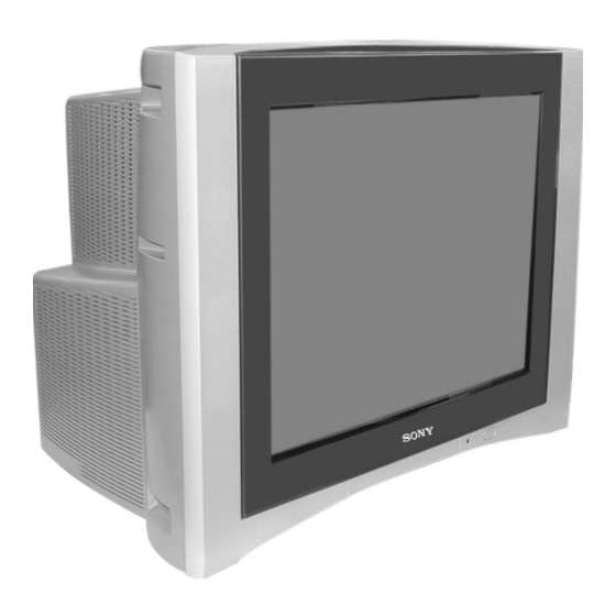
SERVICE MANUAL AG3E CHASSIS MODEL COMMANDER DEST. CHASSIS NO. MODEL COMMANDER DEST. CHASSIS NO. KV-DR29M31 RM-991 Oceania SCC-U41D-A KV-DR29M61 RM-991 Thailand SCC-U46D-A KV-DR29M80,/50 RM-991 India SCC-U57E-A TRINITRON COLOR TV ®... -
Page 3: Table Of Contents
PARTS LIST ARE CRITICAL TO SAFE OPERATION. REPLACE CARBON PAINTED ON THE CRT, AFTER REMOVING THE ANODE. THESE COMPONENTS WITH SONY PARTS WHOSE PART NUMBERS APPEAR AS SHOWN IN THIS MANUAL OR IN SUPPLEMENTS PUBLISHED BY SONY. – 2 –... -
Page 4: Self Diagnostic Function
KV-DR29M31/DR29M61/DR29M80,/50 RM-991 SELF DIAGNOSTIC FUNCTION The units in this manual contain a self-diagnostic function. If an error occurs, the STANDBY/TIMER lamp will automatically begin to flash. The number of times the lamp flashes translates to a probable source of the problem. A definition of the STANDBY/TIMER lamp flash indicators is listed in the instruction manual for the user’s knowledge and reference. - Page 5 KV-DR29M31/DR29M61/DR29M80,/50 RM-991 2. DISPLAY OF STANDBY/TIMER LIGHT FLASH COUNT Diagnostic Item Flash Count* 2 times +B overcurrent 2 times +B overvoltage 3 times 3 times V deflection stop 4 times White balance failure 5 times Lamp ON 0.3 sec. Horizontal Deflection Failure 6 times Lamp OFF 3 sec.
- Page 6 KV-DR29M31/DR29M61/DR29M80,/50 RM-991 5. HANDLING OF SELF-DIAGNOSTIC SCREEN DISPLAY Since the diagnostic results displayed on the screen are not automatically cleared, always check the self-diagnostic screen during repairs. When you have completed the repairs, clear the result display to "0". Unless the result display is cleared to "0", the self-diagnostic function will not be able to detect subsequent faults after completion of the repairs.
-
Page 7: Disassembly
KV-DR29M31/DR29M61/DR29M80,/50 RM-991 SECTION 1 DISASSEMBLY 1-1. REAR COVER REMOVAL 1-2. SPEAKER REMOVAL not used for 2 Rear cover these models 1 Two screws (+BVTP 4 × 16) 1 Fourteen screws (+BVTP 4 × 16) 2 Two screws (Washer Head) (+P4x16) 3 Two screws (+BVTP 4 ×... -
Page 8: Terminal Bracket Removal
(+BVTP 4 × 16) 4 Two hooks 1 Two clips 3 Two clips 1-8. F1 BOARD REMOVAL 1-9. BC1 AND V2 BOARDS REMOVAL 4 V2 Board (KV-DR29M31/M61) 2 BC1 Board P Board (not used for these models) 2 F1 Board... -
Page 9: Picture Tube Removal
1-12. PICTURE TUBE REMOVAL Note: • The picture tube is upside down for KV-DR29M31 (OCE) only and the position for the anode cap and tension springs are changed accordingly. • Please make sure the TV set is not in standing position before removing necessary CRT support located on bottom right and left. - Page 10 KV-DR29M31/DR29M61/DR29M80,/50 RM-991 • REMOVAL OF ANODE-CAP Note: • After removing the anode, short circuit the anode of the picture tube and the anode cap to the metal chassis, CRT shield or carbon paint on the CRT. • REMOVING PROCEDURES Anode Button...
-
Page 11: Service Jig
KV-DR29M31/DR29M61/DR29M80,/50 RM-991 SECTION 2 SERVICE JIG 2-1. JIGS REQUIRED FOR SERVICING REF NO. DESCRIPTION QUANTITY PART NO. REMARK TOOL(20P),SERVICE 3-702-763-01 For A to BC1 board extension TOOL(40P),SERVICE 3-702-764-01 For A to B3 board extension TOOL(50P-A),SERVICE 3-702-765-01 For D to D5 board extension... -
Page 12: Advance Operation
DYNAMIC Child lock OFF* Surround mode Wide mode Color system(video) AUTO Game mode Multi picture(PIP) not used for Teletext mode OFF (KV-DR29M31/M61) these models PIP position Bottom-right Sleep timer OSD recall Wake-up timer Intelligent volume Sound muting ECO mode 3DNR... -
Page 13: Set-Up Adjustments
KV-DR29M31/DR29M61/DR29M80,/50 RM-991 SECTION 5 SET-UP ADJUSTMENTS • Perform the adjustments in the following order : The following adjustments should be made when a complete 1. Beam Landing realignment is required or a new picture tube is installed. • 2. Convergence These adjustments should be performed with rated power 3. -
Page 14: Convergence Adjustment
KV-DR29M31/DR29M61/DR29M80,/50 RM-991 5-2. CONVERGENCE ADJUSTMENT Preparation : V. STAT • Before starting this adjustment, adjust the focus, horizontal size and vertical size. • Receive cross hatch/dot pattern and set picture mode to "STANDARD". (1) Horizontal and Vertical Static Convergence H. STAT VR Center dot V. - Page 15 KV-DR29M31/DR29M61/DR29M80,/50 RM-991 4 BMC (Hexapole) Magnet. (2) Dynamic Convergence Adjustment If the red, green and blue dots are not balanced or aligned, Preparation: then use the BMC magnet to adjust in the manner described • Before starting this adjustment, adjust the horizontal static below.
-
Page 16: Focus Adjustment
KV-DR29M31/DR29M61/DR29M80,/50 RM-991 5-4. NECK ASSY TWIST ADJUSTMENT Fix a Permalloy assy corresponding to the 1. Receive dot/hatch pattern DRC-MF, DRC1250, DYNAMIC. misconverged areas. 2. Turn FOCUS VR fully counter-clockwise. 3. Confirm the dot shape at the screen center. (Fig. 5-4) 4. -
Page 17: Circuit Adjustments
KV-DR29M31/DR29M61/DR29M80,/50 RM-991 SECTION 6 CIRCUIT ADJUSTMENTS 6-2. ADJUSTMENT METHOD 6-1. ADJUSTMENTS WITH COMMANDER Item Number 00 of device GEO Service adjustments to this model can be performed using the This explanation uses V-size as an example. supplied Remote Commander RM-991. - Page 34 KV-DR29M31/DR29M61/DR29M80,/50 RM-991 Abbreviation = V-Compressed Mode = Non-compressed Mode ECO = Eco Mode Sur = Surround = Noise Reduction = Flicker Free = Real 4 = Progressive NOTE • shaded items are fixed data. • no data. • Standard data listed on the Adjustment Item Table are reference values, therefore it may be different for each model and for each mode.
- Page 35 KV-DR29M31/DR29M61/DR29M80,/50 RM-991 OP3 Items Item Initial menu Forced 50/60 KV-DR29M31 KV-DR29M80,/50 KV-DR29M61 Forced 50/60* Forced to 50/60Hz during no signal condition 0 = 60Hz, 1 = 50Hz Initial Menu Activate initial setup or not 0 = Not active 1 = Active...
-
Page 36: Picture Quality Adjustments
KV-DR29M31/DR29M61/DR29M80,/50 RM-991 (ii) NTSC (RF MODE) 6-3. PICTURE QUALITY ADJUSTMENTS Input signal : NTSC Color Bar (75%) to Video Adjustment condition Condition: 1. Set to service mode. 2. Set picture mode to HI-FINE. 3. Set the following condition. Adjusting parameter :... -
Page 37: Deflection Adjustments
KV-DR29M31/DR29M61/DR29M80,/50 RM-991 6-4(4). SUB COLOR ADJUSTMENT (PAL RF MODE) FOR WIDE MODE, DRC1250 (50Hz) Input signal : PAL Color bar (100%) Picture : HI-FINE mode Adjust condition change to WIDE MODE : ON. Condition : COPY (item FOR DRC 1250 (50Hz) MODE and adjust data for the following items). -
Page 38: A Board Adjustment After Ic003 (Memory) Replacement
KV-DR29M31/DR29M61/DR29M80,/50 RM-991 FOR WIDE MODE, DRC 1250 (60Hz) Set to WIDE MODE : ON Copy the DRC 1250 (60Hz) MODE and adjust the following items to obtain optimum image. Raise/lower the data with the buttons. V SIZE V POSITION H SIZE... -
Page 39: Picture Distortion Adjustment
KV-DR29M31/DR29M61/DR29M80,/50 RM-991 6-7. PICTURE DISTORTION ADJUSTMENT (1) PICTURE DISTORTION ADJUSTMENT (2) Item Number 00 – 0B V SAWO WAVE LEVEL GAIN CONTROL (GEO 11 HTR) GEO 0 VSZ (V SIZE) GEO 1 VPS (V POSITION) GEO 2 VLN (V LINEARITY) -
Page 40: Diagrams
KV-DR29M31/DR29M61/DR29M80,/50 KV-DR29M31/DR29M61/DR29M80,/50 RM-991 RM-991 SECTION 7 DIAGRAMS 7-1. BLOCK DIAGRAM IC3001 COMPONENT I/F Q3015 SELYOUT SELVOUT Y-BUFFER SELHOUT Q3018 SELCBOUT U-BUFFER Q3023 SELCROUT V-BUFFER EXTCLK/XTAL X3001 CRYSTAL V U Y Q8351 BUFFER IC8309 Q8352 } AMP DVD PROGRESSIVE Q8337 IC4301 V U Y >... - Page 44 KV-DR29M31/DR29M61/DR29M80,/50 KV-DR29M31/DR29M61/DR29M80,/50 RM-991 RM-991 V PROT Q6819, Q6820 CN6801 CN6806 V. OUT IC6800 AFC PIS PUMP UP V– Q6801 H PROT V PROT – H– D6605 V COMP AC IN MAIN PRE RGB CN6604 RECT H OUT DRIVE PIN OUT...
- Page 45 KV-DR29M31/DR29M61/DR29M80,/50 KV-DR29M31/DR29M61/DR29M80,/50 RM-991 RM-991 CN6101 CN6102 : S-MICRO : S-MICRO (DEFLECTION CONTROL CIRCUIT) QPDV DQP DRIVE QPAV Q6107 HCENT 2SB1142-T HLIN SAD 2 DFPH SDA 1 QPPH SDA 0 IC6501 LA6510 N/S-OUT CN6100 – – IC6205 CXA1875AM PROT 1 2 3 4 5 6 7 8 9 10...
-
Page 46: Schematic Diagrams
KV-DR29M31/DR29M61/DR29M80,/50 RM-991 7-2. SCHEMATIC DIAGRAMS Note: • All capacitors are in µF unless otherwise noted. • All electrolytic capacitors are rated at 50V unless otherwise noted. • All resistors are in ohms. kΩ = 1000Ω, MΩ = 1000kΩ • Indication of resistance which does not have rating electrical power is as follows. -
Page 47: A Board Schematic Diagrams
KV-DR29M31/DR29M61/DR29M80,/50 KV-DR29M31/DR29M61/DR29M80,/50 RM-991 RM-991 (1) A Board Schematic Diagrams CN1193 :S-MICRO TO H1 BOARD CN1932 R4483 C4392 R2200 R4364 R4342 R4318 IC1204 C4395 R4485 :CHIP R4344 R4343 1.0M :CHIP AN7582Z R4449 Q4333 R4427 R2202 R4348 R4339 R4320 R4463 :CHIP R4365... - Page 48 KV-DR29M31/DR29M61/DR29M80,/50 KV-DR29M31/DR29M61/DR29M80,/50 RM-991 RM-991 CN8401 :BTOB TO BC1 BOARD CN1118 CN2001 :BTOB R8351 C8330 TO V2 BOARD 4.7k 1 16V :CHIP +6.5V :CHIP CN5801 R IN R8320 (TEXT) C8331 1 16V :CHIP R8512 L IN R8352 C8372 C8300 :CHIP 4.7k R8468 0.47 16V:CHIP...
-
Page 49: B3 Board Schematic Diagram
KV-DR29M31/DR29M61/DR29M80,/50 KV-DR29M31/DR29M61/DR29M80,/50 RM-991 RM-991 (2) B3 Board Schematic Diagram R545 C514 R546 C516 IC507 HP-SHIFTER R542 R541 Q505 R543 C515 DRIVER R687 IC605 R547 R544 FL601 R598 L604 Q601 C639 C638 PQ07VZ012ZP CKD510JB1A105ST 10UH 0.01 0.01 1.8V REG :CHIP :CHIP... -
Page 50: D Board Schematic Diagram
KV-DR29M31/DR29M61/DR29M80,/50 KV-DR29M31/DR29M61/DR29M80,/50 RM-991 RM-991 (3) D Board Schematic Diagram CN6607 R6102 FB6103 C6102 T6100 0.0047 R6108 Transformer Converter 500V C6108 C6107 0.0047 C6318 500V 0.01 FB6101 C6100 250V C6111 D6642 D6105 0.0047 500V 0.0047 500V ERA22-08 1SS119-25 (POWER SUPPLY, DEFLECTION HV) -
Page 51: D5 Board Schematic Diagram
KV-DR29M31/DR29M61/DR29M80,/50 KV-DR29M31/DR29M61/DR29M80,/50 RM-991 RM-991 (4) D5 Board Schematic Diagram CN6101 CN6102 :S-MICRO :S-MICRO TO VM BOARD CN5402 TO DY (pin 1 ~ pin 8) (Rotation Coil) 135V R6546 R6547 Q6106 IC6205 :RN-CP MSD601-RT1 R6134 R6135 CXA1875AM-T4 DQP V PARA PRE DRIVE... -
Page 52: C Board Schematic Diagram
KV-DR29M31/DR29M61/DR29M80,/50 KV-DR29M31/DR29M61/DR29M80,/50 RM-991 RM-991 (5) C Board Schematic Diagram CN9007 CONNECTOR ONE TOUCH TO D BOARD CN6810 R9055 C9034 820k 0.5W JW9017 RV9002 2.2M C9031 R9058 R9056 0.0047 NL9002 CN9002 820k C9032 1/2W 0.5W R9087 680p L9001 Q9005 2.2UH TO D BOARD... -
Page 53: V2 Board Schematic Diagram
KV-DR29M31/DR29M61/DR29M80,/50 KV-DR29M31/DR29M61/DR29M80,/50 RM-991 RM-991 (6) V2 Board Schematic Diagram (KV-DR29M31/DR29M61) (TELETEXT) D5801 D5802 IC5801 MIMA152WA-T1 SAA5264PS/M3 R5831 TEXT DECODER 4.7k C5828 RN-CP C5825 P2.0/PWM P1.5 R5830 P2.1/PWMO P1.4 4.7k :RN-CP R5829 P2.2/PWM1 :RN-CP R5828 P2.3/PWM2 :RN-CP C5837 C5817 P1.3 3.3V P2.4/PWM3... -
Page 54: Bc1 Board Schematic Diagram
KV-DR29M31/DR29M61/DR29M80,/50 KV-DR29M31/DR29M61/DR29M80,/50 RM-991 RM-991 (7) BC1 Board Schematic Diagram R2312 IC2300 1K:CHIP R2311 TC90A69F(ELP) C2327 Q2302 C2329 C2326 1.2K :B2H C2300 C2312 MSD601-RT1 L2306 :CHIP 0.01 2D COMB 0.01 BUFFER 10UH R2313 L2304 C2321 :CHIP B:CHIP :CHIP 0:CHIP 27UH 0.01 ( 2D &... -
Page 55: H1, H2 And J Boards Schematic Diagrams
KV-DR29M31/DR29M61/DR29M80,/50 KV-DR29M31/DR29M61/DR29M80,/50 RM-991 RM-991 (8) H1, H2 and J Boards Schematic Diagrams CN1934 CN1905 CN1932 :S-MICRO :S-MICRO :S-MICRO TO A BOARD TO A BOARD TO A BOARD CN1193 CN8301 CN1190 (pin 5~10) D1930 HZS9.1NB2 PROTECTOR D1907 NNCD9.1A-T1 PROTECT JW1933 D1944... -
Page 56: F1 And Vm Boards Schematic Diagram
KV-DR29M31/DR29M61/DR29M80,/50 KV-DR29M31/DR29M61/DR29M80,/50 RM-991 RM-991 (9) F1 and VM Boards Schematic Diagrams VDR161 JW1602 CN1603 ERZV14D621 JW1606 CN1601 :TAB FB1601 JW1605 JW1601 F1601 TIME-LAG TO POWER CORD 5.0A R1602 250V T1601 AC IN AC OUT T1602 AC IN AC OUT CN1602... - Page 57 KV-DR29M31/DR29M61/DR29M80,/50 RM-991 A Board ✼ Mark List KV-DR29M31 KV-DR29M80,/50 KV-DR29M61 C016 47P :CHIP 47P :CHIP 15P :CHIP C017 68P :CHIP 68P :CHIP 27P :CHIP C1202 47 35V 47 25V 47 35V C1203 47 35V 47 25V 47 35V C1220 1 50V...
- Page 58 KV-DR29M31/DR29M61/DR29M80,/50 RM-991 A Board ✼ Mark List KV-DR29M31 KV-DR29M80,/50 KV-DR29M61 Q003 MSD601-RT1 2SC2712-YG MSD601RT1 Q004 MSD601-RT1 2SC2712-YG MSD601RT1 Q313 MSD601-RT1 2SC2712-YG MSD601RT1 Q8302 MSD601-RT1 2SC2712-YG MSD601RT1 Q8303 MSD601-RT1 2SC2712-YG MSD601RT1 Q8304 MSD601-RT1 2SC2712-YG MSD601RT1 Q8306 MSD601-RT1 2SC2712-YG MSD601RT1 Q8307 MSD601-RT1...
- Page 59 KV-DR29M31/DR29M61/DR29M80,/50 RM-991 J Board ✼ Mark List KV-DR29M31 KV-DR29M80,/50 KV-DR29M61 C2418 1 63V C2419 1 63V Note: The parts indicated as "#" in this circuit diagram are not listed here, as they are not used for these models. VM Board ✼ Mark List...
- Page 60 KV-DR29M31/DR29M61/DR29M80,/50 RM-991 D Board ✼ Mark List KV-DR29M31 KV-DR29M80,/50 KV-DR29M61 C6105 0.1 25V :CHIP 0.1 :CHIP 0.1 25V :CHIP C6606 100P :CHIP C6609 1 63V C6610 100P :CHIP C6611 0.001 :CHIP C6616 2.2 63V C6621 1200 250V C6622 1200 250V...
- Page 61 KV-DR29M31/DR29M61/DR29M80,/50 RM-991 D Board ✼ Mark List KV-DR29M31 KV-DR29M80,/50 KV-DR29M61 R6867 4.7K 4.7K R6868 4.7K 4.7K R6875 R6884 100K 100K R6908 R6909 RY6602 “RELAY, AC POWER” VD6601 ENE471D-20A Note: The parts indicated as "#" in this circuit diagram are not listed here, as they are not used for these models.
- Page 62 KV-DR29M31/DR29M61/DR29M80,/50 RM-991 7-3. VOLTAGE LIST AND WAVEFORM A BOARD VOLTAGE LIST AND WAVEFORM Pin No. Voltage[v] Pin No. Voltage[v] Pin No. Voltage[v] IC001 IC1203 5.0Vp-p IC1204 28.0 3.2Vp-p IC002 14.0 29.0 14.0 (2.4)[3.1] 14.0 IC1205 IC003 IC100 IC1200 IC1207 416mVp-p...
- Page 63 KV-DR29M31/DR29M61/DR29M80,/50 RM-991 A BOARD VOLTAGE LIST AND WAVEFORM Pin No. Voltage[v] Pin No. Voltage[v] Pin No. Voltage[v] IC1208 (1.2)[0.8] IC3002 4.74 4.5Vp-p NTSC3.58 IC2200 4.0Vp-p IC2600 10.0 IC3003 IC2601 IC2602 IC2603 IC3001 1.7Vp-p NTSC3.58 IC4301 1.9Vp-p 1.8Vp-p NTSC3.58 2.0Vp-p – 75 –...
- Page 64 KV-DR29M31/DR29M61/DR29M80,/50 RM-991 A BOARD VOLTAGE LIST AND WAVEFORM Pin No. Voltage[v] Pin No. Voltage[v] Pin No. Voltage[v] IC4302 IC8306 IC4304 IC8302 IC8309 IC8310 600mVp-p 1.2Vp-p NTSC3.58 960mVp-p IC8312 Q001 1.0Vp-p Q002 Q003 1.1Vp-p Q004 – 76 –...
- Page 65 KV-DR29M31/DR29M61/DR29M80,/50 RM-991 A BOARD VOLTAGE LIST AND WAVEFORM Pin No. Voltage[v] Pin No. Voltage[v] Pin No. Voltage[v] Q008 Q3015 Q4323 Q101 Q3018 Q4324 Q301 10.0 Q3024 Q4330 10.0 Q302 10.7 Q3025 Q4333 (0)[-0.3] 10.4 Q313 Q3300 Q8301 10.0 Q1200 Q4301...
- Page 66 KV-DR29M31/DR29M61/DR29M80,/50 RM-991 A BOARD VOLTAGE LIST AND WAVEFORM Pin No. Voltage[v] Pin No. Voltage[v] Q8334 Q8361 Q8335 Q8362 Q8336 Q8363 Q8351 Q8364 Q8352 Q8365 (2.2)[3.1] (1.5)[2.4] Q8356 VM BOARD VOLTAGE LIST AND WAVEFORM Pin No. Voltage[v] Q5400 Q5401 Q5402 Q5403...
- Page 67 KV-DR29M31/DR29M61/DR29M80,/50 RM-991 D5 BOARD VOLTAGE LIST AND WAVEFORM Pin No. Voltage[v] Pin No. Voltage[v] Pin No. Voltage[v] IC6100 Q6203 -0.5 Q6205 (3.7)[4.1] Q6206 Q6207 Q6208 11.8 Q6209 -1.5 Q6210 5.63 -1.4 Q6211 IC6201 Q6212 (8.9)[2.4] IC6501 -11.4 (2.0)[4.0] -11.4 -2.8 (4.1)[2.2]...
- Page 68 KV-DR29M31/DR29M61/DR29M80,/50 RM-991 D5 BOARD VOLTAGE LIST AND WAVEFORM Pin No. Voltage[v] Pin No. Voltage[v] Pin No. Voltage[v] Q6418 Q6508 Q6419 Q6509 8.8Vp-p Q6420 Q6421 208mVp-p 472mVp-p Q6422 NTSC3.58 Q6423 2.4Vp-p 752mVp-p Q6424 (0)[0.6] Q6425 Q6427 800mVp-p 9.0Vp-p Q6437 Q6438 736mVp-p 840mVp-p NTSC3.58...
- Page 69 KV-DR29M31/DR29M61/DR29M80,/50 RM-991 V2 BOARD VOLTAGE LIST AND WAVEFORM (KV-DR29M31/DR29M61) Pin No. Voltage[v] Pin No. Voltage[v] IC5801 Q5801 Q5803 Q5805 Q5810 – 81 –...
- Page 70 KV-DR29M31/DR29M61/DR29M80,/50 RM-991 C BOARD VOLTAGE LIST AND WAVEFORM Pin No. Voltage[v] Pin No. Voltage[v] Pin No. Voltage[v] Q9001 IC9001 Q9003 Q9004 116Vp-p (158)[154] NTSC3.58 (152)[148] IC9002 Q9005 Q9009 108Vp-p (168)[170] Q9010 IC9003 Q9011 96Vp-p NTSC3.58 86Vp-p J9001 (565)[560] 3.2Vp-p (158)[154] 23.6Vp-p...
- Page 71 KV-DR29M31/DR29M61/DR29M80,/50 RM-991 BC1 BOARD VOLTAGE LIST AND WAVEFORM Pin No. Voltage[v] Pin No. Voltage[v] Pin No. Voltage[v] IC2001 Q2006 IC2004 Q2007 Q2008 (8.9)[5.9] (5.0)[2.1] Q2009 Q2010 Q2011 Q2012 Q2013 Q2014 Q2015 IC2005 (3.2)[3.6] Q2016 IC2300 Q2018 Q2019 (3.3)[3.6] Q2300 Q2301...
- Page 72 KV-DR29M31/DR29M61/DR29M80,/50 RM-991 B3 BOARD VOLTAGE LIST AND WAVEFORM Pin No. Voltage[v] Pin No. Voltage[v] Pin No. Voltage[v] IC504 (0.8)[1.4] 820mVp-p NTSC3.58 IC505 640mVp-p IC506 IC507 656mVp-p NTSC3.58 680mVp-p IC601 670mVp-p 10Vp-p – 84 –...
- Page 73 KV-DR29M31/DR29M61/DR29M80,/50 RM-991 B3 BOARD VOLTAGE LIST AND WAVEFORM Pin No. Voltage[v] Pin No. Voltage[v] Pin No. Voltage[v] IC605 (0.6)[1.0] IC801 (1.5)[1.9] (0.6)[2.2] (1.4)[0.8] (1.5)[1.1] IC603 IC802 IC604 (0)[3.1] (3.2)[0] IC602 (3.2)[0] – 85 –...
- Page 74 KV-DR29M31/DR29M61/DR29M80,/50 RM-991 B3 BOARD VOLTAGE LIST AND WAVEFORM Pin No. Voltage[v] Pin No. Voltage[v] Pin No. Voltage[v] Q504 Q505 Q516 Q517 Q518 Q521 (1.4)[1.7] IC803 Q522 Q523 IC804 Q601 Q602 Q501 Q603 Q502 Q604 Q901 106mVp-p NTSC3.58 Q902 Q903 86mVp-p...
- Page 75 KV-DR29M31/DR29M61/DR29M80,/50 RM-991 D BOARD VOLTAGE LIST AND WAVEFORM Pin No. Voltage[v] Pin No. Voltage[v] Pin No. Voltage[v] IC6600 IC6804 10.3 Q6800 IC6805 13.3 Q6801 IC6806 Q6802 17.8 10.6 Q6803 IC6807 Q6804 PH6601 Q6805 (73)[71] IC6601 PH6602 Q6806 -0.5 (63)[60] -17.5 IC6607 134.1...
- Page 76 KV-DR29M31/DR29M61/DR29M80,/50 RM-991 D BOARD VOLTAGE LIST AND WAVEFORM Pin No. Voltage[v] Pin No. Voltage[v] 7.6Vp-p 2.7Vp-p NTSC3.58 NTSC3.58 2.2Vp-p 53.6Vp-p 9.2Vp-p 1.8Vp-p 260Vp-p 8.9Vp-p 370Vp-p 7.8Vp-p NTSC3.58 2.6Vp-p 2.3Vp-p 8.8Vp-p – 88 –...
-
Page 77: Printed Wiring Boards And Parts Location
KV-DR29M31/DR29M61/DR29M80,/50 KV-DR29M31/DR29M61/DR29M80,/50 RM-991 RM-991 7-4. PRINTED WIRING BOARDS AND PARTS LOCATION PRINTED WIRING BOARDS [MICON, AUDIO AMP., TUVIF 1 & 2, REGULATORS, RGB JUNGLE, YCT, AV SW, VIDEO/AUDIO SIGNAL] – A board (Component Side) – A BOARD (Component Side) Q4330 D-9... - Page 78 KV-DR29M31/DR29M61/DR29M80,/50 KV-DR29M31/DR29M61/DR29M80,/50 RM-991 RM-991 PRINTED WIRING BOARDS A BOARD (Conductor Side) [MICON, AUDIO AMP., TUVIF 1 & 2, REGULATORS, RGB JUNGLE, YCT, AV SW, VIDEO/AUDIO SIGNAL] Q8321 D-11 Q8326 D-10 Q8333 B-9 IC100 F-10 Q8334 B-10 IC1200 G-1 – A board (Conductor Side) –...
- Page 79 KV-DR29M31/DR29M61/DR29M80,/50 KV-DR29M31/DR29M61/DR29M80,/50 RM-991 RM-991 PRINTED WIRING BOARDS NOTE: The circuit indicated at left contains high voltage of over 1220 Vp-p. Please pay attention when inspecting or [POWER SUPPLY, DEFLECTION HV] repairing it to prevent an electric shock. – D board –...
- Page 80 KV-DR29M31/DR29M61/DR29M80,/50 RM-991 PRINTED WIRING BOARDS [DIGITAL REALITY CREATION-MF, 3D NOISE REDUCTION] – B3 board (Component Side) – B3 board (Component Side) Q502 Q503 R668 Q504 IC504 C556 Q505 IC505 JR603 Q521 IC507 Q522 IC508 R653 Q523 IC601 IC601 Q605 IC602...
- Page 81 KV-DR29M31/DR29M61/DR29M80,/50 RM-991 [2D & 3D DIGITAL COMB] – BC1 board (Component Side) – BC1 board (Component Side) IC2001 B-4 IC2004 A-2 CN2002 IC2005 C-4 TRANSISTOR RV2001 Q2003 B-2 R2032 Q2004 A-2 Q2004 Q2009 B-3 C2054 Q2011 C-2 R2050 Q2012 A-3...
- Page 82 KV-DR29M31/DR29M61/DR29M80,/50 KV-DR29M31/DR29M61/DR29M80,/50 RM-991 RM-991 PRINTED WIRING BOARDS [DEFLECTION CONTROL [S-TERMINAL INPUT, AV INPUT, [VIDEO AMPLIFIER] CIRCUIT] PRESET KEY, PHONE OUT] – D5 board – – C board – CN6102 CN9001 LP9001 CN6101 LP9004 C6517 RV9003 EY9010 EY9012 EY9014 JW6100 JW6101...
- Page 83 KV-DR29M31/DR29M61/DR29M80,/50 RM-991 PRINTED WIRING BOARDS [COMPONENT IN] [VELOCITY MODULATION] – J board – C2411 C2410 C2418 J2410 JW3451 – VM board – CN5401 JW5405 R5423 FB5400 L5400 R5415 R5412 R5413 JW5403 R5418 D5401 D5403 LP5401 JW5404 D5404 – 99 –...
- Page 84 KV-DR29M31/DR29M61/DR29M80,/50 RM-991 PRINTED WIRING BOARDS [POWER SW, LED, [AC LINE FILTER] SIRCS RECEIVER] – H2 board – R1975 – F1 board – JW1607 JW1608 EY1613 EY1615 EY1601 EY1625 EY1602 EY1605 EY1623 EY1606 R1603 EY1620 EY1619 EY1621 EY1622 JW1605 JW1606 EY1603...
- Page 85 KV-DR29M31/DR29M61/DR29M80,/50 RM-991 PRINTED WIRING BOARDS [TELETEXT ] – V2 board – (KV-DR29M31/DR29M61) JW 5810 C5829 JW 5809 Q5810 Q5805 C5827 JW 5808 R5899 C5820 R5844 C5826 R5846 FB5804 JW 5805 JR5804 JW 5807 C5837 IC5802 JR5811 C5835 C5831 Q5808 FB5805...
-
Page 86: Semiconductors
KV-DR29M31/DR29M61/DR29M80,/50 RM-991 7-5. SEMICONDUCTORS DIODE CATHODE CATHODE ANODE ANODE (GRN) ANODE CATHODE ANODE (GRN) CATHODE ANODE ERC06-15SA SPB-25MVWF D4SB60L D1N20R RD22ESB1 MA111-TX U05G ERA38-06 RD30ESB2 MM3Z3V9T1 ERA85-009 RD6.8ESB1 MMDL914T1 NNCD9.1A-T1 1SS119-25 RD5.6SB3 RD10ESB2 1SS133T-77 RD12ESB1 RD18ESB2 ANODE CATHODE D1NL20U-TR S3L20UF4 UDZSTE-179.1B... - Page 87 KV-DR29M31/DR29M61/DR29M80,/50 RM-991 TOP VIEW STV9379A BA09T CXD2095AQ AN7582Z TA7805S RPM7140-H5 BA12T CXP750096-048Q UPC64083GF-3BA TRANSISTOR TOP VIEW Quad Flat L-leaded Package TOP VIEW Pin 20~996 PQ09RF2 TDA6111Q/N4 NJM2870F33(TE2) CXA2069Q 2SC2500-B 2SD774-34 CXA2151Q CXA2163AQ-T6 TC90A90FG- (BH,DRY) LETTER SIDE 2SA1037AK-T146-R MSB709-RT1 2SA1175-HFE 2SA2005...
-
Page 88: Exploded Views
KV-DR29M31/DR29M61/DR29M80,/50 RM-991 SECTION 8 EXPLODED VIEWS NOTE: • • Items marked " ∗ " are not stocked since Items with no part number and no The components identified by description are not stocked because they are seldom required for routine... -
Page 89: Chassis
: 7-685-663-71 SCREW +BVTP 4 × 16 REF. NO. PART NO. DESCRIPTION REMARK REF. NO. PART NO. DESCRIPTION REMARK * A-1400-491-A MOUNTED PWB, H1 (KV-DR29M31) ! 1-453-325-12 TRANSFORMER ASSY, FLYBACK (KV-DR29M31/M61) * A-1401-539-A MOUNTED PWB, H1 (KV-DR29M80,/50) (NX-4522//M3B4) * A-1400-692-A MOUNTED PWB, H1 (KV-DR29M61) ! 1-453-349-12... -
Page 90: Picture Tube
REF. NO. PART NO. DESCRIPTION REMARK REF. NO. PART NO. DESCRIPTION REMARK X-4039-977-2 CABINET ASSY 152-154,172-175 * 4-063-935-21 CUSHION (50 x 550), DGC (KV-DR29M31/M61) (KV-DR29M31/M61) * 4-069-208-01 CUSHION (50 x 550), DGC (KV-DR29M80,/50) X-4042-218-1 CABINET ASSY 152-154,172-175 4-064-883-03 HOLDER, DGC (KV-DR29M31/M61) (KV-DR29M80,/50) -
Page 91: Electrical Parts List
REF NO. PART NO. DESCRIPTION REMARK REF NO. PART NO. DESCRIPTION REMARK * A-1302-670-A COMPLETE PWB, A (KV-DR29M31) C111 1-163-005-91 CERAMIC CHIP 470PF 10.00% 50V * A-1302-650-A COMPLETE PWB, A (KV-DR29M80,/50) C112 1-126-933-11... - Page 92 KV-DR29M31/DR29M61/DR29M80,/50 RM-991 The components identified by shading and mark ! are critical for safety. Replace only with part number specified. REF NO. PART NO. DESCRIPTION REMARK REF NO. PART NO. DESCRIPTION REMARK C1270 1-163-019-00 CERAMIC CHIP 0.0068UF 10.00% 50V C3037...
- Page 93 KV-DR29M31/DR29M61/DR29M80,/50 RM-991 The components identified by shading and mark ! are critical for safety. Replace only with part number specified. REF NO. PART NO. DESCRIPTION REMARK REF NO. PART NO. DESCRIPTION REMARK C4367 1-216-295-91 SHORT CHIP C8372 1-164-004-11 CERAMIC CHIP 0.1UF...
- Page 94 KV-DR29M31/DR29M61/DR29M80,/50 RM-991 The components identified by shading and mark ! are critical for safety. Replace only with part number specified. REF NO. PART NO. DESCRIPTION REMARK REF NO. PART NO. DESCRIPTION REMARK D4301 8-719-081-97 DIODE MMDL914T1 < JACK > D4302...
- Page 95 KV-DR29M31/DR29M61/DR29M80,/50 RM-991 The components identified by shading and mark ! are critical for safety. Replace only with part number specified. REF NO. PART NO. DESCRIPTION REMARK REF NO. PART NO. DESCRIPTION REMARK Q3018 8-729-102-07 TRANSISTOR 2SC2223-F13 R036 1-216-033-00 RES-CHIP 1/10W...
- Page 96 KV-DR29M31/DR29M61/DR29M80,/50 RM-991 The components identified by shading and mark ! are critical for safety. Replace only with part number specified. REF NO. PART NO. DESCRIPTION REMARK REF NO. PART NO. DESCRIPTION REMARK R1220 1-216-081-00 RES-CHIP 1/10W R3014 1-216-049-11 RES-CHIP 1/10W...
- Page 97 KV-DR29M31/DR29M61/DR29M80,/50 RM-991 The components identified by shading and mark ! are critical for safety. Replace only with part number specified. REF NO. PART NO. DESCRIPTION REMARK REF NO. PART NO. DESCRIPTION REMARK R4354 1-216-057-00 RES-CHIP 2.2K 1/10W R4488 1-216-057-00 RES-CHIP 2.2K...
- Page 98 KV-DR29M31/DR29M61/DR29M80,/50 RM-991 The components identified by shading and mark ! are critical for safety. Replace only with part number specified. REF NO. PART NO. DESCRIPTION REMARK REF NO. PART NO. DESCRIPTION REMARK R8374 1-216-039-00 RES-CHIP 1/10W R8495 1-216-081-00 RES-CHIP 1/10W...
- Page 99 8-719-041-97 DIODE MA113-(TX) (KV-DR29M61) (KV-DR29M61) D1214 8-719-041-97 DIODE MA113-(TX) (KV-DR29M61) C3353 1-126-933-11 ELECT 100UF 20.00% 16V (KV-DR29M61) D2200 8-719-158-35 DIODE RD9.1SB (KV-DR29M31/M80,/50) C3354 1-126-967-11 ELECT 47UF 20.00% 50V D2200 8-719-069-60 DIODE UDZSTE-179.1B (KV-DR29M61) (KV-DR29M61) D2201 8-719-158-35 DIODE RD9.1SB (KV-DR29M31/M80,/50) C3355...
- Page 100 DESCRIPTION REMARK REF NO. PART NO. DESCRIPTION REMARK D8312 8-719-069-60 DIODE UDZSTE-179.1B (KV-DR29M61) Q8304 8-729-230-49 TRANSISTOR 2SC2712-YG (KV-DR29M80,/50) D8313 8-719-158-35 DIODE RD9.1SB (KV-DR29M31/M80,/50) Q8306 8-729-010-25 TRANSISTOR MSD601-RT1 D8313 8-719-069-60 DIODE UDZSTE-179.1B (KV-DR29M61) (KV-DR29M31/M61) D8314 8-719-158-35 DIODE RD9.1SB (KV-DR29M31/M80,/50) Q8306 8-729-230-49...
- Page 101 1-163-021-91 CERAMIC CHIP 0.01UF 10.00% 50V C634 1-163-021-91 CERAMIC CHIP 0.01UF 10.00% 50V * A-1300-290-A COMPLETE PWB, B3 (KV-DR29M31) * A-1300-754-A COMPLETE PWB, B3 (KV-DR29M80,/50) C635 1-163-021-91 CERAMIC CHIP 0.01UF 10.00% 50V * A-1300-385-A COMPLETE PWB, B3 (KV-DR29M61) C636 1-163-021-91 CERAMIC CHIP 0.01UF...
- Page 102 KV-DR29M31/DR29M61/DR29M80,/50 RM-991 The components identified by shading and mark ! are critical for safety. Replace only with part number specified. REF NO. PART NO. DESCRIPTION REMARK REF NO. PART NO. DESCRIPTION REMARK C819 1-163-038-91 CERAMIC CHIP 0.1UF < CHIP CONDUCTOR >...
- Page 103 KV-DR29M31/DR29M61/DR29M80,/50 RM-991 The components identified by shading and mark ! are critical for safety. Replace only with part number specified. REF NO. PART NO. DESCRIPTION REMARK REF NO. PART NO. DESCRIPTION REMARK R673 1-216-073-91 RES-CHIP 1/10W R524 1-216-295-91 SHORT CHIP...
- Page 104 ************************************************************** C2097 1-163-231-11 CERAMIC CHIP 15PF 5.00% C2100 1-163-038-91 CERAMIC CHIP 0.1UF * A-1300-298-A COMPLETE PWB, BC1 (KV-DR29M31) C2101 1-163-031-91 CERAMIC CHIP 0.01UF * A-1300-757-A COMPLETE PWB, BC1 (KV-DR29M80,/50) C2103 1-163-031-91 CERAMIC CHIP 0.01UF * A-1300-388-A COMPLETE PWB, BC1 (KV-DR29M61)
- Page 105 KV-DR29M31/DR29M61/DR29M80,/50 RM-991 The components identified by shading and mark ! are critical for safety. Replace only with part number specified. REF NO. PART NO. DESCRIPTION REMARK REF NO. PART NO. DESCRIPTION REMARK C2313 1-163-021-91 CERAMIC CHIP 0.01UF 10.00% 50V L2306...
- Page 106 KV-DR29M31/DR29M61/DR29M80,/50 RM-991 The components identified by shading and mark ! are critical for safety. Replace only with part number specified. REF NO. PART NO. DESCRIPTION REMARK REF NO. PART NO. DESCRIPTION REMARK R2048 1-216-049-11 RES-CHIP 1/10W < CRYSTAL > R2049...
- Page 107 DESCRIPTION REMARK **************************************************************** D9011 1-216-295-91 SHORT CHIP D9012 1-216-295-91 SHORT CHIP * A-1400-488-A MOUNTED PWB, C (KV-DR29M31) D9013 1-216-295-91 SHORT CHIP * A-1401-537-A MOUNTED PWB, C (KV-DR29M80,/50) * A-1400-690-A MOUNTED PWB, C (KV-DR29M61) ********************************** < IC > 4-382-854-01 SCREW (M3X8), P, SW (+)
- Page 108 6.8K 1/10W **************************************************************** R9068 1-216-101-00 RES-CHIP 150K 1/10W R9070 1-216-037-00 RES-CHIP 1/10W * A-1300-940-A COMPLETE PWB, D (KV-DR29M31) R9071 1-216-037-00 RES-CHIP 1/10W * A-1300-756-A COMPLETE PWB, D (KV-DR29M80,/50) * A-1302-653-A COMPLETE PWB, D (KV-DR29M61) R9072 1-216-037-00 RES-CHIP 1/10W *********************************** R9073...
- Page 109 KV-DR29M31/DR29M61/DR29M80,/50 RM-991 The components identified by shading and mark ! are critical for safety. Replace only with part number specified. REF NO. PART NO. DESCRIPTION REMARK REF NO. PART NO. DESCRIPTION REMARK C6654 1-126-936-11 ELECT 3300UF 20.00% 16V C6885 1-162-131-11...
- Page 110 KV-DR29M31/DR29M61/DR29M80,/50 RM-991 The components identified by shading and mark ! are critical for safety. Replace only with part number specified. REF NO. PART NO. DESCRIPTION REMARK REF NO. PART NO. DESCRIPTION REMARK D6806 8-719-911-19 DIODE 1SS119-25 < PHOTO COUPLER >...
- Page 111 KV-DR29M31/DR29M61/DR29M80,/50 RM-991 The components identified by shading and mark ! are critical for safety. Replace only with part number specified. REF NO. PART NO. DESCRIPTION REMARK REF NO. PART NO. DESCRIPTION REMARK R6624 1-218-895-11 METAL CHIP 100K 0.50% 1/10W R6826...
- Page 112 KV-DR29M31/DR29M61/DR29M80,/50 RM-991 The components identified by shading and mark ! are critical for safety. Replace only with part number specified. REF NO. PART NO. DESCRIPTION REMARK REF NO. PART NO. DESCRIPTION REMARK < THERMISTOR > C6843 1-115-339-11 CERAMIC CHIP 0.1UF 10.00% 50V...
- Page 113 RELAY, AC POWER (KV-DR29M80,/50) (KV-DR29M80,/50) R6679 1-249-437-11 CARBON 1/4W < TRANSFORMER > (KV-DR29M31/M61) R6679 1-249-401-11 CARBON 1/4W (KV-DR29M80,/50) T6803 ! 1-453-325-12 TRANSFORMER ASSY, FLYBACK R6681 1-249-429-11 CARBON 1/4W (NX-4522//M3B4) (KV-DR29M31/M61) (KV-DR29M31/M61) T6803 ! 1-453-349-12 TRANSFORMER ASSY, FLYBACK (NX-4522//M3I4) (KV-DR29M80,/50) – 129 –...
- Page 114 0.001UF 10.00% 50V **************************************************************** C6519 1-126-934-11 ELECT 220UF 20.00% 16V * A-1400-486-A MOUNTED PWB, D5 (KV-DR29M31) * A-1401-549-A MOUNTED PWB, D5 (KV-DR29M80,/50) < CONNECTOR > * A-1400-689-A MOUNTED PWB, D5 (KV-DR29M61) *********************************** * CN6100 1-793-498-11 CONNECTOR, BOARD TO BOARD 50P...
- Page 115 KV-DR29M31/DR29M61/DR29M80,/50 RM-991 The components identified by shading and mark ! are critical for safety. Replace only with part number specified. REF NO. PART NO. DESCRIPTION REMARK REF NO. PART NO. DESCRIPTION REMARK IC6401 8-759-659-67 IC LA6393DLL Q6216 8-729-216-22 TRANSISTOR 2SA1162-G...
- Page 116 KV-DR29M31/DR29M61/DR29M80,/50 RM-991 The components identified by shading and mark ! are critical for safety. Replace only with part number specified. REF NO. PART NO. DESCRIPTION REMARK REF NO. PART NO. DESCRIPTION REMARK R6133 1-218-887-11 METAL CHIP 0.50% 1/10W R6401 1-216-864-11...
- Page 117 KV-DR29M31/DR29M61/DR29M80,/50 RM-991 The components identified by shading and mark ! are critical for safety. Replace only with part number specified. REF NO. PART NO. DESCRIPTION REMARK REF NO. PART NO. DESCRIPTION REMARK R6489 1-216-829-11 METAL CHIP 4.7K 1/10W R6611 1-216-825-11 METAL CHIP 2.2K...
- Page 118 CERAMIC CHIP 0.1UF 10.00% 50V (KV-DR29M80,/50) C6413 1-162-970-11 CERAMIC CHIP 0.01UF 10.00% 25V < DIODE > (KV-DR29M31/M61) D6204 8-719-081-97 DIODE MMDL914T1 (KV-DR29M31/M80,/50) C6413 1-163-021-91 CERAMIC CHIP 0.01UF 10.00% 50V (KV-DR29M80,/50) C6414 1-126-960-11 ELECT 20.00% 50V < TRANSISTOR > (KV-DR29M31/M61) C6414...
- Page 119 DESCRIPTION REMARK REF NO. PART NO. DESCRIPTION REMARK * A-1400-490-A MOUNTED PWB, F1 (KV-DR29M31) * A-1400-491-A MOUNTED PWB, H1 (KV-DR29M31) * A-1401-538-A MOUNTED PWB, F1 (KV-DR29M80,/50) * A-1401-539-A MOUNTED PWB, H1 (KV-DR29M80,/50) * A-1400-691-A MOUNTED PWB, F1 (KV-DR29M61) * A-1400-692-A MOUNTED PWB, H1 (KV-DR29M61)
- Page 120 20.00% 35V (KV-DR29M80,/50) (KV-DR29M31/M61) C1910 1-125-796-91 ELECT 47UF 20.00% 25V (KV-DR29M80,/50) **************************************************************** < RESISTOR > * A-1400-492-A MOUNTED PWB, H2 (KV-DR29M31) * A-1401-540-A MOUNTED PWB, H2 (KV-DR29M80,/50) R1913 1-249-429-11 CARBON 1/4W * A-1400-693-A MOUNTED PWB, H2 (KV-DR29M61) (KV-DR29M31/M61) ************************************ R1913 1-249-393-11...
- Page 121 REF NO. PART NO. DESCRIPTION REMARK REF NO. PART NO. DESCRIPTION REMARK * A-1400-500-A MOUNTED PWB, J (KV-DR29M31) * A-1400-711-A MOUNTED PWB, V2 (KV-DR29M31) * A-1401-542-A MOUNTED PWB, J (KV-DR29M80,/50) * A-1400-847-A MOUNTED PWB, V2 (KV-DR29M61) * A-1400-695-A MOUNTED PWB, J (KV-DR29M61) ******************************** ********************************** <...
- Page 122 CARBON 1/4W R5421 1-249-385-11 CARBON 1/4W **************************************************************** R5422 1-249-405-11 CARBON 1/4W * A-1400-499-A MOUNTED PWB, VM (KV-DR29M31) R5423 1-215-915-11 METAL OXIDE * A-1401-541-A MOUNTED PWB, VM (KV-DR29M80,/50) R5425 1-216-805-11 METAL CHIP 1/10W * A-1400-694-A MOUNTED PWB, VM (KV-DR29M61) ************************************ 4-382-854-11...
- Page 123 **************************************************************** R5418 1-249-414-11 CARBON 1/4W (KV-DR29M31/M61) REMOTE COMMANDER R5418 1-247-897-11 CARBON 560K 1/4W ********************** (KV-DR29M80,/50) 1-477-313-11 REMOTE COMMANDER (RM-991) 4-079-833-01 REMOTE COMMANDER BATTERY COVER Sony Corporation Sony Technology Malaysia Sdn. Bhd. English 9-872-386-01 Visual Products 2003.9 – 139 –...
-
Page 124: Operating Instructions
4-088-297-16 (1) Trinitron Color TV Operating Instructions • Before operating the unit, please read this manual thoroughly and retain it for future reference. KV-DR34 KV-DR29 © 2002 Sony Corporation... - Page 125 WARNING • Dangerously high voltages are present inside the TV. • TV operating voltage: 110 – 240 V AC. (For Australia/New Zealand only: 220 - 240 V AC.) • Do not plug in the power cord until you have completed making all other connections;...
- Page 126 Do not plug in too many appliances to the same To prevent fire or shock hazard, do not expose the power socket. Do not damage the power cord. TV to rain or moisture. Pull the power cord out by the plug. Do not pull the power cord itself.
-
Page 127: Securing The Tv
x Securing the TV To prevent the TV from falling, use the supplied screws, clamps and band to secure the TV. 20 mm 3.8 mm screws clamps band Screw the band to the TV stand and to the provided hole at the rear of your TV. (1) Put a cord or chain through the clamps. - Page 128 Table of Contents Installation Menu Adjustment Getting Started ........6 Introducing the menu system ..18 Setting up your TV Changing the “PICTURE” setting ... 21 (“INITIAL SETUP”) ......7 Changing the “SOUND” setting ..23 Changing the Picture-in-Picture (“PIP”) setting (KV-DR34M89/ Overview of Controls DR29M39/DR29M89 only) ....
-
Page 129: Installation
Installation x Getting Started Step 1 Insert the batteries (supplied) into the remote. Note • Do not use old or different types of batteries together. Step 2 Connect the antenna cable (not supplied) to 8 (antenna input) at the rear of the TV. •... -
Page 130: Setting Up Your Tv ("Initial Setup")
x Setting up your TV (“INITIAL SETUP”) SOUND MENU MENU When you turn on your TV for the first time, PIP PROGR the “INITIAL SETUP” menu will appear. V/v/ENTER ENTER This menu allows you to change the menu language, adjust the picture position and DRC-MF PIP PROGR preset the TV channels automatically. -
Page 131: Overview Of Controls
Overview of Controls TV front and rear panels TV rear panel ENTER SELECT AUTO L(MONO) MENU PROGR PROGR TV front panel ENTER SELECT L(MONO) AUTO MENU PROGR PROGR Button/Terminal Function Page Turn off or turn on the TV. – Standby indicator. –... -
Page 132: Remote Control
Remote control Button Function Page 1 ?/1 Turn off temporarily or – turn on the TV. Display the TV input. – 4 0 – 9, - Input numbers. – 5 JUMP Jump to previous program – number. 9 SURROUND Select surround mode. 0 WIDE MODE Select wide-mode (16:9). - Page 133 continued Button Function Page Menu operations MENU Display or cancel the menu. ENTER Confirm selected items. V, v, B, b Select and adjust items. Teletext operations (green label) Enlarge the Teletext display. 0 – 9 Input Teletext page number JUMP PROGR +/–...
-
Page 134: Advanced Operations
Advanced Operations Selecting the picture and sound modes You can select picture and sound modes and adjust the setting to your preference in the “PERSONAL” option. Selecting the picture mode Press PIC MODE to select the desired picture mode. Select “DYNAMIC”... -
Page 135: Viewing Higher Quality Pictures With Drc-Mf
• The DRC-MF mode is not selectable when the “GAME MODE” or Picture-in-Picture (“PIP”) mode is turned on. The DRC-MF logo ( ) and “DRC-MF” are trademarks of Sony Corporation. Viewing the picture in wide mode When receiving a wide-mode (16:9) signal, the picture will appear “squeezed”... -
Page 136: Watching Picture-In-Picture (Pip)
Watching Picture-in-Picture (PIP) B KV-DR34M89/DR29M39/DR29M89 only With the PIP feature, you can display two different TV programs or video input at the same time by using the button. JUMP SOUND SOUND Press MENU PIP PROGR Display a sub screen PIP PROGR +/ To cancel the sub screen, press ENTER PIP PROGR –... -
Page 137: Selecting A Tv Program Using Pip (Kv-Dr34M89/Dr29M39/ Dr29M89 Only)
x Selecting a TV program using PIP B KV-DR34M89/DR29M39/DR29M89 only You can select your desired TV program directly from the PIP sub screen by using the PIP PROGR +/– buttons. SOUND MENU PIP PROGR Press PIP PROGR +/– until the desired program PIP PROGR +/ appears in the sub screen. -
Page 138: Setting The Timers
x Setting the timers You can set your TV to turn on and off automatically by using the WAKE UP and SLEEP timers respectively. Setting the Wake Up timer Press until the desired period of time appears on the screen. WAKE UP TIMER:10M (After 10 minutes) JUMP... -
Page 139: Enjoying Stereo Or Bilingual Programs (Kv-Dr29M39/ Dr29M31 Only)
x Enjoying stereo or bilingual programs KV-DR29M39/DR29M31 only You can enjoy stereo sound or bilingual programs of NICAM and A2 stereo systems by using the A/B button. When receiving a NICAM program Broadcasting On-screen display (Selected sound) NICAM MONO NICAM stereo (Regular sound) (Stereo sound) -
Page 140: Viewing Teletext
x Viewing Teletext Some TV stations broadcast an information service called Teletext which allows you to receive various information, such as stock market reports and news. You can use the buttons on the remote to view Teletext. Do this display a Teletext Press . -
Page 141: Menu Adjustment
Menu Adjustment x Introducing the menu system The MENU button lets you open a menu and change the settings of your TV. The following is an overview of the menu system. Return icon PICTURE icon Name of the current S E T UP menu SOUND icon L ANGUAGE :... - Page 142 Level 3/Function Page Level 1 Level 2 Change the menu language: “SETUP” “LANGUAGE” “ENGLISH” t “ ”(Chinese) t ”(Arabic) t “ “ ”(Thai) “PIC ROTATION” Adjust the picture position. Reduce power consumption of your TV. “ECO MODE” Adjust each program number settings. “PROGRAM SETUP”...
- Page 143 continued How to use the menu Press MENU to display MENU PIP PROGR MENU P I C T URE the menu. DRC - MF : DRC 1 2 5 0 P I C T URE MO DE : DYNAM I ENTER 3 D - NR : OF F WI DE MODE : OF F...
-
Page 144: Changing The "Picture" Setting
x Changing the “PICTURE” setting The “PICTURE” menu allows you to adjust the picture settings. Press MENU. P I C T URE Make sure the “PICTURE” icon ( ) is DRC - MF : 1 2 5 0 selected, then press ENTER. P I C T URE MODE : DYNAM I 3D - NR : OF F WI DE MODE : OF F... - Page 145 continued Adjusting the “ADJUST” items under “PICTURE MODE” Press V or v to select the desired item (e.g.,“COLOR”), then press ENTER. COLOR Adjust the value according to the following table, then press ENTER. Press v or B to Press V or b to “PICTURE”...
-
Page 146: Changing The "Sound" Setting
x Changing the “SOUND” setting The “SOUND” menu allows you to adjust the sound settings. Press MENU. Press V or v to select the “SOUND” SOUND icon ( ), then press ENTER. SOUND MODE DYNAM I C SURROUND : OF F I N T E L L I GEN T VO L : OF F Press V or v to select the desired item SOUND... - Page 147 continued Adjusting the “ADJUST” items under “SOUND MODE” Press V or v to select the desired item (e.g., “BALANCE”), then press ENTER. BALANCE Adjust the value according to the following table, then press ENTER . Press v or B to Press V or b to “BASS”...
-
Page 148: Changing The Picture-In-Picture
Changing the Picture-in-Picture (“PIP”) setting B KV-DR34M89/DR29M39/DR29M89 only The “PIP” menu allows you to display a sub screen, change the sub screen position and exchange pictures between the main and sub screens. Press MENU. Press V or v to select the “PIP” icon ( P I P POS I T I ON : then press ENTER. -
Page 149: Changing The "Setup" Setting
Changing the “SETUP” setting The “SETUP” menu allows you to change the menu language, adjust the picture position, reduce your TV power consumption, set up your program numbers and select the color system. Press MENU. Press V or v to select the “SETUP” S E T UP icon ( ), then press ENTER. - Page 150 Adjusting each program number settings (“PROGRAM SETUP”) Select “PROGRAM SETUP” from the “SETUP” menu. Select “PR” and press ENTER. Press V or v PROGRAM S E T PR : to select the desired program number you S K I P : OF F want to adjust, then press ENTER.
-
Page 151: Changing The Channel Preset ("Ch Preset") Setting
x Changing the Channel Preset (“CH PRESET”) setting The “CH PRESET” menu allows you to preset channels automatically, manually preset channels and select the TV system. Press MENU. Press V or v to select the “CH PRESET” icon CH PRE S E T ), then press ENTER. - Page 152 Presetting channels manually After selecting “MANUAL PROGRAM”, MANUA L PROGRAM select the program number to which you PR : T V S Y S : B / G want to preset a channel. S ENS : H I GH VH F L OW (1) Make sure “PR”...
- Page 153 continued If you are not satisfied with the picture and sound quality, you may be able to MANUA L PROGRAM improve them by using the “FINE” tuning PR : 1 0 AU TO feature. T V S Y S : I MANUA L S ENS : H I G (1) Press V or v to select “FINE”, then press...
-
Page 154: Additional Information
Additional Information x Connecting optional components Connecting to the video input terminal ( t ) S Video cable TV front panel (not supplied) Audio/Video cable Camcorder (not supplied) L(MONO) TV rear panel Video game equipment Antenna cable (not supplied) Audio/Video cable (not supplied) S Video cable (not supplied) - Page 155 continued Connecting a DVD player to the component video input terminal ( 1 Using an audio cable, connect R and L under (component video input) on your TV to the LINE OUT, AUDIO R and L output connectors on your DVD player. 2 Using a component video cable, connect Y, P , and P under...
-
Page 156: Troubleshooting
TV, VCR and at the wall. damaged. • The antenna setup is • Check the antenna setup. – inappropriate. Contact a Sony dealer for advice. • Channel presetting is • Display the “CH PRESET” menu and Noisy sound inappropriate or select “MANUAL PROGRAM” to preset incomplete. - Page 157 Dotted lines or – equipment near the TV. interference from cars, stripes neon signs, hair dryers, • Check the antenna setup. Contact a Sony – power generators, etc. dealer for advice. • Use a highly directional antenna. – Double images or •...
- Page 158 • Check the antenna cable and connection or the cable is damaged. on the TV, VCR and on the wall. • The antenna setup is • Check the antenna setup. Contact a Sony – Stereo broadcast inappropriate. dealer for advice.
- Page 159 (standby) indicator flashes. Press ! indicator on your possible problems. (main power) to turn off your TV. TV flashes red – Contact your nearest Sony service center. several times after every three seconds. • Some shooting games Cannot play which involve pointing shooting games.
-
Page 160: Specifications
Specifications KV-DR29M81 KV-DR29M89 KV-DR34M89 Note KV-DR29M31 KV-DR29M39 Power requirements 110-240 V AC, 50/60 Hz 220-240 V AC, 50/60 Hz Australia/New Zealand only Power consumption (W) Indicated on the rear of the TV Television system B/G, I, D/K, M Color system PAL, PAL 60, SECAM, NTSC3.58, NTSC4.43... - Page 161 °Ë Õ π‡√‘ Ë ¡ °“√„™È ß “π°√ÿ ≥ “ÕË “ π§Ÿ Ë ¡ ◊ Õ π’ È ‚ ¥¬≈–‡Õ’ ¬ ¥∑— È ß À¡¥·≈–‡°Á ∫ √— ° …“§Ÿ Ë ¡ ◊ Õ ‰«È • ”À√— ∫ ÕÈ “ ßÕ‘ ß „π‚Õ°“ µË Õ Ê‰ª KV-DR34 KV-DR29 © 2002 Sony Corporation...
- Page 162 WARNING • Dangerously high voltages are present inside the TV. • TV operating voltage: 220 – 240 V AC. • Do not plug in the power cord until you have completed making all other connections; otherwise a minimum leakage current might flow through the antenna and other terminals to ground.
- Page 163 Do not plug in too many appliances to the same To prevent fire or shock hazard, do not expose the power socket. Do not damage the power cord. TV to rain or moisture. Pull the power cord out by the plug. Do not pull the power cord itself.
- Page 164 x Securing the TV To prevent the TV from falling, use the supplied screws, clamps and band to secure the TV. 20 mm 3.8 mm screws clamps band Screw the band to the TV stand and to the provided hole at the rear of your TV. (1) Put a cord or chain through the clamps.
- Page 165 Table of Contents Installation Menu Adjustment Getting Started ........6 Introducing the menu system ..18 Setting up your TV Changing the “PICTURE” setting ... 21 (“INITIAL SETUP”) ......7 Changing the “SOUND” setting ..23 Changing the Picture-in-Picture (“PIP”) setting Overview of Controls (KV-DR34M69 only) ......
-
Page 166: Installation
Installation x Getting Started Step 1 Insert the batteries (supplied) into the remote. Note • Do not use old or different types of batteries together. Step 2 Connect the antenna cable (not supplied) to 8 (antenna input) at the rear of the TV. •... -
Page 167: Setting Up Your Tv ("Initial Setup")
x Setting up your TV (“INITIAL SETUP”) MENU SOUND When you turn on your TV for the first time, MENU PIP PROGR the “INITIAL SETUP” menu will appear. V/v/ENTER This menu allows you to change the menu ENTER language, adjust the picture position and DRC-MF preset the TV channels automatically. -
Page 168: Overview Of Controls
Overview of Controls TV front and rear panels TV rear panel ENTER SELECT AUTO L(MONO) MENU PROGR PROGR TV front panel ENTER SELECT L(MONO) AUTO MENU PROGR PROGR Button/Terminal Function Page Turn off or turn on the TV. – Standby indicator. –... -
Page 169: Remote Control
Remote control Button Function Page 1 ?/1 Turn off temporarily or – turn on the TV. Display the TV input. – 4 0 – 9, - Input numbers. – 5 JUMP Jump to previous program – number. 9 SURROUND Select surround mode. 0 WIDE MODE Select wide-mode (16:9). - Page 170 continued Button Function Page Menu operations MENU Display or cancel the menu. ENTER Confirm selected items. V, v, B, b Select and adjust items. Teletext operations (green label) (KV-DR34M69/DR29M61 only) Enlarge the Teletext display. JUMP 0 – 9 Input Teletext page number SOUND PROGR +/–...
-
Page 171: Advanced Operations
Advanced Operations Selecting the picture and sound modes You can select picture and sound modes and adjust the setting to your preference in the “PERSONAL” option. Selecting the picture mode Press PIC MODE to select the desired picture mode. Select “DYNAMIC”... -
Page 172: Viewing Higher Quality Pictures With Drc-Mf
• The DRC-MF mode is not selectable when the “GAME MODE” or Picture-in-Picture (“PIP”) mode is turned on. The DRC-MF logo ( ) and “DRC-MF” are trademarks of Sony Corporation. Viewing the picture in wide mode When receiving a wide-mode (16:9) signal, the picture will appear “squeezed”... -
Page 173: Watching Picture-In-Picture (Pip)
Watching Picture-in-Picture (PIP) B KV-DR34M69 only With the PIP feature, you can display two different TV programs or video input at the same time by using the button. JUMP SOUND SOUND Press MENU PIP PROGR Display a sub screen PIP PROGR +/ To cancel the sub screen, press ENTER PIP PROGR –... -
Page 174: Selecting A Tv Program Using Pip (Kv-Dr34M69 Only)
x Selecting a TV program using PIP B KV-DR34M69 only You can select your desired TV program directly from the PIP sub screen by using the PIP PROGR +/– buttons. SOUND Press PIP PROGR +/– until the desired program MENU PIP PROGR appears in the sub screen. -
Page 175: Setting The Timers
x Setting the timers You can set your TV to turn on and off automatically by using the WAKE UP and SLEEP timers respectively. Setting the Wake Up timer Press until the desired period of time appears on the screen. WAKE UP TIMER:10M (After 10 minutes) JUMP... -
Page 176: Enjoying Stereo Or Bilingual Programs
x Enjoying stereo or bilingual programs You can enjoy stereo sound or bilingual programs of NICAM and A2 stereo systems by using the A/B button. When receiving a NICAM program Broadcasting On-screen display (Selected sound) NICAM MONO NICAM stereo (Regular sound) (Stereo sound) NICAM JUMP... -
Page 177: Viewing Teletext (Kv-Dr34M69/Dr29M61 Only)
x Viewing Teletext B KV-DR34M69/DR29M61 only Some TV stations broadcast an information service called Teletext which allows you to receive various information, such as stock market reports and news. You can use the buttons on the remote to view Teletext. Do this display a Teletext Press... -
Page 178: Menu Adjustment
Menu Adjustment x Introducing the menu system The MENU button lets you open a menu and change the settings of your TV. The following is an overview of the menu system. Return icon PICTURE icon Name of the current S E T UP menu SOUND icon L ANGUAGE :... - Page 179 Level 3/Function Page Level 1 Level 2 Change the menu language: “SETUP” “LANGUAGE” “ENGLISH” t “ ”(Chinese) t ”(Arabic) t “ “ ”(Thai) “PIC ROTATION” Adjust the picture position. Reduce power consumption of your TV. “ECO MODE” Adjust each program number settings. “PROGRAM SETUP”...
- Page 180 continued How to use the menu Press MENU to display MENU PIP PROGR MENU P I C T URE the menu. DRC - MF : DRC 1 2 5 0 P I C T URE MO DE : DYNAM I ENTER 3 D - NR : OF F WI DE MODE : OF F...
-
Page 181: Changing The "Picture" Setting
x Changing the “PICTURE” setting The “PICTURE” menu allows you to adjust the picture settings. Press MENU. P I C T URE Make sure the “PICTURE” icon ( ) is DRC - MF : 1 2 5 0 selected, then press ENTER. P I C T URE MODE : DYNAM I 3D - NR : OF F WI DE MODE : OF F... - Page 182 continued Adjusting the “ADJUST” items under “PICTURE MODE” Press V or v to select the desired item (e.g.,“COLOR”), then press ENTER. COLOR Adjust the value according to the following table, then press ENTER. Press v or B to Press V or b to “PICTURE”...
-
Page 183: Changing The "Sound" Setting
x Changing the “SOUND” setting The “SOUND” menu allows you to adjust the sound settings. Press MENU. Press V or v to select the “SOUND” SOUND icon ( ), then press ENTER. SOUND MODE DYNAM I C SURROUND : OF F I N T E L L I GEN T VO L : OF F Press V or v to select the desired item SOUND... - Page 184 continued Adjusting the “ADJUST” items under “SOUND MODE” Press V or v to select the desired item (e.g., “BALANCE”), then press ENTER. BALANCE Adjust the value according to the following table, then press ENTER . Press v or B to Press V or b to “BASS”...
-
Page 185: Changing The Picture-In-Picture ("Pip") Setting
Changing the Picture-in-Picture (“PIP”) setting B KV-DR34M69 only The “PIP” menu allows you to display a sub screen, change the sub screen position and exchange pictures between the main and sub screens. Press MENU. Press V or v to select the “PIP” icon ( P I P then press ENTER. -
Page 186: Changing The "Setup" Setting
Changing the “SETUP” setting The “SETUP” menu allows you to change the menu language, adjust the picture position, reduce your TV power consumption, set up your program numbers and select the color system. Press MENU. Press V or v to select the “SETUP” S E T UP icon ( ), then press ENTER. - Page 187 Adjusting each program number settings (“PROGRAM SETUP”) Select “PROGRAM SETUP” from the “SETUP” menu. Select “PR” and press ENTER. Press V or v PROGRAM S E T to select the desired program number you PR : S K I P : OF F want to adjust, then press ENTER.
-
Page 188: Changing The Channel Preset ("Ch Preset") Setting
x Changing the Channel Preset (“CH PRESET”) setting The “CH PRESET” menu allows you to preset channels automatically, manually preset channels and select the TV system. Press MENU. Press V or v to select the “CH PRESET” icon CH PRE S E T ), then press ENTER. - Page 189 Presetting channels manually After selecting “MANUAL PROGRAM”, MANUA L PROGRAM select the program number to which you PR : T V S Y S : B / G want to preset a channel. S ENS : H I GH VH F L OW (1) Make sure “PR”...
- Page 190 continued If you are not satisfied with the picture and sound quality, you may be able to MANUA L PROGRAM improve them by using the “FINE” tuning PR : 1 0 AU TO feature. T V S Y S : I MANUA L S ENS : H I G (1) Press V or v to select “FINE”, then press...
-
Page 191: Additional Information
Additional Information x Connecting optional components Connecting to the video input terminal ( t ) S Video cable TV front panel (not supplied) Audio/Video cable Camcorder (not supplied) L(MONO) TV rear panel Video game equipment Antenna cable (not supplied) Audio/Video cable (not supplied) S Video cable (not supplied) - Page 192 continued Connecting a DVD player to the component video input terminal ( 1 Using an audio cable, connect R and L under (component video input) on your TV to the LINE OUT, AUDIO R and L output connectors on your DVD player. 2 Using a component video cable, connect Y, P , and P under...
-
Page 193: Troubleshooting
TV, VCR and at the wall. damaged. • The antenna setup is • Check the antenna setup. – inappropriate. Contact a Sony dealer for advice. • Channel presetting is • Display the “CH PRESET” menu and Noisy sound inappropriate or select “MANUAL PROGRAM” to preset incomplete. - Page 194 – Dotted lines or interference from cars, equipment near the TV. stripes neon signs, hair dryers, • Check the antenna setup. Contact a Sony – power generators, etc. dealer for advice. – • Broadcast signals are • Use a highly directional antenna.
- Page 195 • Check the antenna cable and connection • The connection is loose on the TV, VCR and on the wall. or the cable is damaged. • Check the antenna setup. Contact a Sony – • The antenna setup is Stereo broadcast dealer for advice.
- Page 196 (standby) indicator flashes. Press ! indicator on your possible problems. (main power) to turn off your TV. TV flashes red Contact your nearest Sony service center. several times after every three seconds. • Some shooting games Cannot play which involve pointing shooting games.
-
Page 197: Specifications
894 × 690 × 569 786 × 596 × 514 Dimensions (w/h/d, mm) Mass (kg) Design and specifications are subject to change without notice. Sony Thai Co., Ltd. 2126 Kromadit Building, New Petchburi Road, Bangkapi, Huaykwang, Bangkok 10320 Sony Corporation Additional Information... - Page 198 4-099-790-11 (2) Trinitron Color TV Operating Instructions • Before operating the unit, please read this manual thoroughly and retain it for future reference. KV-DR29 © 2003 Sony Corporation...
- Page 199 WARNING • Dangerously high voltages are present inside the TV. • TV operating voltage: 110 – 240 V AC. • Do not plug in the power cord until you have completed making all other connections; otherwise a minimum leakage current might flow through the antenna and other terminals to ground.
- Page 200 Do not plug in too many appliances to the same Do not place any objects on the TV. power socket. Do not damage the power cord. Pull the power cord out by the plug. Do not pull the power cord itself. Even if your TV is turned off, it is still connected to the AC power source Install the TV on a stable TV stand and floor which (mains) as long as the power cord is plugged in.
- Page 201 x Securing the TV To prevent the TV from falling, use the supplied screws, clamps and band to secure the TV. 20 mm 3.8 mm screws clamps band Screw the band to the TV stand and to the provided hole at the rear of your TV. (1) Put a cord or chain through the clamps.
- Page 202 Table of Contents Installation Menu Adjustment Getting Started ........6 Introducing the menu system ..15 Setting up your TV Changing the “PICTURE” setting ... 18 (“INITIAL SETUP”) ......7 Changing the “SOUND” setting ..20 Changing the “SETUP” setting ..22 Changing the Channel Preset Overview of Controls (“CH PRESET”) setting .....
-
Page 203: Installation
Installation x Getting Started Step 1 Insert the batteries (supplied) into the remote. Note • Do not use old or different types of batteries together. Step 2 Connect the antenna cable (not supplied) to 8 (antenna input) at the rear of the TV. •... -
Page 204: Setting Up Your Tv ("Initial Setup")
x Setting up your TV (“INITIAL SETUP”) MENU SOUND When you turn on your TV for the first time, MENU PIP PROGR the “INITIAL SETUP” menu will appear. V/v/ ENTER This menu allows you to change the menu ENTER language, adjust the picture position and DRC-MF preset the TV channels automatically. -
Page 205: Overview Of Controls
Overview of Controls TV front and rear panels TV rear panel ENTER SELECT AUTO L(MONO) MENU PROGR PROGR TV front panel ENTER SELECT L(MONO) AUTO MENU PROGR PROGR Button/Terminal Function Page Turn off or turn on the TV. – Standby indicator. –... -
Page 206: Remote Control
Remote control Button Function Page 1 ?/1 Turn off temporarily or – turn on the TV. Display the TV input. – 4 0 – 9, - Input numbers. – 5 JUMP Jump to previous program – number. 9 SURROUND Select surround mode. 0 WIDE MODE Select wide-mode (16:9). - Page 207 continued Button Function Page Menu operations MENU Display or cancel the menu. ENTER Confirm selected items. V, v, B, b Select and adjust items. Teletext operations (green label) 0 – 9 JUMP PROGR +/– SOUND MENU PIP PROGR Not function for your TV. –...
-
Page 208: Advanced Operations
Advanced Operations Selecting the picture and sound modes You can select picture and sound modes and adjust the setting to your preference in the “PERSONAL” option. Selecting the picture mode Press PIC MODE to select the desired picture mode. Select “DYNAMIC”... -
Page 209: Viewing Higher Quality Pictures With Drc-Mf
• The DRC-MF mode is not selectable when the “GAME MODE” mode is turned on. The DRC-MF logo ( ) and “DRC-MF” are trademarks of Sony Corporation. Viewing the picture in wide mode When receiving a wide-mode (16:9) signal, the picture will appear “squeezed”... -
Page 210: Listening With Surround Sound
Listening with surround sound You can use the SURROUND button to listen to the sound effects of a concert hall or movie theater. ENTER Select DRC-MF PIP PROGR SOUND WIDE SURROUND “TruSurround”* listen to the surround sound that MODE MODE MODE SURROUND PROGR... -
Page 211: Setting The Timers
x Setting the timers You can set your TV to turn on and off automatically by using the WAKE UP and SLEEP timers respectively. Setting the Wake Up timer Press until the desired period of time appears on the screen. WAKE UP TIMER:10M (After 10 minutes) JUMP... -
Page 212: Menu Adjustment
Menu Adjustment x Introducing the menu system The MENU button lets you open a menu and change the settings of your TV. The following is an overview of the menu system. Return icon PICTURE icon Name of the current S E T UP menu SOUND icon L ANGUAGE :... - Page 213 continued Level 1 Level 2 Level 3/Function Page Change the menu language: “SETUP” “LANGUAGE” “ENGLISH” t “ ”(Chinese) t “ ”(Arabic) t “ ”(Thai) “PIC ROTATION” Adjust the picture position. Reduce power consumption of your TV. “ECO MODE” Adjust each program number settings. “PROGRAM SETUP”...
- Page 214 How to use the menu Press MENU to display MENU PIP PROGR MENU P I C T URE the menu. DRC - MF : DRC 1 0 5 0 P I C T URE MO DE : DYNAM I ENTER 3 D - NR : OF F WI DE MODE : OF F DRC-MF...
-
Page 215: Changing The "Picture" Setting
x Changing the “PICTURE” setting The “PICTURE” menu allows you to adjust the picture settings. Press MENU. P I C T URE Make sure the “PICTURE” icon ( ) is DRC - MF : 1 2 5 0 selected, then press ENTER. P I C T URE MODE : DYNAM I 3D - NR : OF F WI DE MODE : OF F... - Page 216 Adjusting the “ADJUST” items under “PICTURE MODE” Press V or v to select the desired item (e.g.,“COLOR”), then press ENTER. COLOR Adjust the value according to the following table, then press ENTER. Press v or B to Press V or b to “PICTURE”...
-
Page 217: Changing The "Sound" Setting
x Changing the “SOUND” setting The “SOUND” menu allows you to adjust the sound settings. Press MENU. Press V or v to select the “SOUND” SOUND icon ( ), then press ENTER. SOUND MODE DYNAM I C SURROUND : OF F I N T E L L I GEN T VO L : OF F Press V or v to select the desired item SOUND... - Page 218 Adjusting the “ADJUST” items under “SOUND MODE” Press V or v to select the desired item (e.g., “BALANCE”), then press ENTER. BALANCE Adjust the value according to the following table, then press ENTER . Press v or B to Press V or b to “BASS”...
-
Page 219: Changing The "Setup" Setting
Changing the “SETUP” setting The “SETUP” menu allows you to change the menu language, adjust the picture position, reduce your TV power consumption, set up your program numbers and select the color system. Press MENU. Press V or v to select the “SETUP” S E T UP icon ( ), then press ENTER. - Page 220 Adjusting each program number settings (“PROGRAM SETUP”) Select “PROGRAM SETUP” from the “SETUP” menu. Select “PR” and press ENTER. Press V or v PROGRAM S E T to select the desired program number you PR : S K I P : OF F want to adjust, then press ENTER.
-
Page 221: Changing The Channel Preset ("Ch Preset") Setting
x Changing the Channel Preset (“CH PRESET”) setting The “CH PRESET” menu allows you to preset channels automatically, manually preset channels and select the TV system. Press MENU. Press V or v to select the “CH PRESET” icon CH PRE S E T ), then press ENTER. - Page 222 Presetting channels manually After selecting “MANUAL PROGRAM”, MANUA L PROGRAM select the program number to which you PR : T V S Y S : B / G want to preset a channel. VH F L OW F I NE : AU TO (1) Make sure “PR”...
- Page 223 continued If you are not satisfied with the picture MANUA L PROGRAM and sound quality, you may be able to PR : 1 0 AU TO improve them by using the “FINE” tuning T V S Y S : I MANUA L feature.
-
Page 224: Additional Information
Additional Information x Connecting optional components Connecting to the video input terminal ( t ) S Video cable TV front panel (not supplied) Audio/Video cable Camcorder (not supplied) L(MONO) TV rear panel Video game equipment Antenna cable (not supplied) Audio/Video cable (not supplied) S Video cable (not supplied) - Page 225 continued Connecting a DVD player to the component video input terminal ( 1 Using an audio cable, connect R and L under (component video input) on your TV to the LINE OUT, AUDIO R and L output connectors on your DVD player. 2 Using a component video cable, connect Y, P , and P under...
-
Page 226: Troubleshooting
TV, VCR and at the wall. damaged. • The antenna setup is • Check the antenna setup. – inappropriate. Contact a Sony dealer for advice. • Channel presetting is • Display the “CH PRESET” menu and Noisy sound inappropriate or select “MANUAL PROGRAM” to preset incomplete. - Page 227 Dotted lines or interference from cars, equipment near the TV. stripes neon signs, hair dryers, – • Check the antenna setup. Contact a Sony power generators, etc. dealer for advice. – • Broadcast signals are • Use a highly directional antenna.
- Page 228 (standby) indicator flashes. Press ! possible problems. (main power) to turn off your TV. TV flashes red Contact your nearest Sony service center. several times after every three seconds. • Some shooting games Cannot play which involve pointing shooting games.
-
Page 229: Specifications
Output: 1 Stereo minijack Picture tube 29 in. Tube size (cm) Measured diagonally Screen size (cm) Measured diagonally 786 × 596 × 514 Dimensions (w/h/d, mm) Mass (kg) Design and specifications are subject to change without notice. Sony Corporation Additional Information...
Need help?
Do you have a question about the TRINITRON KV-DR29M31 and is the answer not in the manual?
Questions and answers