Table of Contents
Advertisement
Quick Links
SERVICE MANUAL
1
2
3
4
5
6
7
8
9
0
VIDEO
Refer to the SERVICE MANUAL of VHS MECHANICAL
ADJUSTMENTS VI for MECHANICAL ADJUSTMENTS.
(9-921-647-11)
System
Color system
LF1MI:
PAL, MESECAM, NTSC 3.58,
NTSC 4.43
LF1AS:
PAL, NTSC 3.58, NTSC 4.43
TV system
LF1MI:
B/G, D/K, I, M
LF1AS:
B/G
Channel coverage
LF1MI:
B/G: VHF E2 to E12/UHF E21 to E69/
CATV S01 to S05, S1 to S41
D/K: VHF R1 to R12/UHF R21 to R69
I: VHF SA4 to SA13/UHF B21 to B69/
CATV S01 to S05, S1 to S41
M: VHF A2 to A13/UHF A14 to A69/
CATV A-8 to A-1, A to W, W+1 to W+84
LF1AS:
VHF AS0 to AS12, AS5A, AS9A
UHF AS28 to AS69
CATV S01 to S05, S1 to S41
RF output signal
LF1MI:
UHF channels 21 to 69
LF1AS:
UHF channels 28 to 69
Aerial out
75-ohm asymmetrical aerial socket
SLV-LF1
SPECIFICATIONS
Inputs and Outputs
LINE-1 IN
VIDEO IN, phono jack (1)
Input signal: 1 Vp-p, 75 ohms, unbalanced,
sync negative
AUDIO IN, phono jack (2)
Input level: 327 mVrms
Input impedance: more than 47 kilohms
LINE OUT
VIDEO OUT, phono jack (1)
Output signal: 1 Vp-p, 75 ohms,
unbalanced, sync negative
AUDIO OUT, phono jack (2)
Standard output: 327 mVrms
Load impedance: 47 kilohms
Output impedance: less than 10 kilohms
General
Power requirements
110 - 240 V AC, 50/60 Hz (LF1MI)
220 - 240 V AC, 50 Hz (LF1AS)
Power consumption
16 W
Operating temperature
5°C to 40°C
Storage temperature
–20°C to 60°C
SLV-LF1
RMT-V313/V313A
Australian Model
Hong Kong Model
Dimensions
Approx. 430 x 97 x 292 mm (w/h/d)
including projecting parts and controls
Mass
Approx. 4.6 kg
Supplied accessories
Remote commander (1)
R6 (size AA) batteries (2)
Aerial cable (1)
Plug adaptor (1) (LF1MI)
Design and specifications are subject to
change without notice.
VIDEO CASSETTE RECORDER
SLV-LF1AS
SLV-LF1MI
S MECHANISM
Advertisement
Table of Contents

Related Manuals for Sony SLV-LF1


Summary of Contents for Sony SLV-LF1
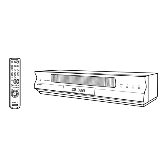
- Page 1 SLV-LF1 RMT-V313/V313A SERVICE MANUAL Australian Model SLV-LF1AS Hong Kong Model SLV-LF1MI S MECHANISM VIDEO SLV-LF1 Refer to the SERVICE MANUAL of VHS MECHANICAL ADJUSTMENTS VI for MECHANICAL ADJUSTMENTS. (9-921-647-11) SPECIFICATIONS System Dimensions Inputs and Outputs Color system LINE-1 IN Approx. 430 x 97 x 292 mm (w/h/d)
- Page 2 LINE WITH MARK ON THE SCHEMATIC DIAGRAMS AND IN THE PARTS LIST ARE CRITICAL TO SAFE OPERATION. REPLACE THESE COMPONENTS WITH SONY PARTS WHOSE PART NUMBERS APPEAR AS SHOWN IN THIS MANUAL OR IN SUPPLEMENTS PUB- LISHED BY SONY. – 2 –...
-
Page 3: Table Of Contents
TABLE OF CONTENTS Section Title Page Section Title Page Feature Difference ..............3 INTERFACE, IC PIN FUNCTION DESCRIPTION SERVICE NOTE ............... 5 5-1. System Control-Video Block Interface (MA-402 BOARD IC101) ..........5-1 GENERAL 5-2. System Control-Servo Peripheral Circuit Interface (MA-402 BOARD IC101) ..........5-1 Getting Started .............. -
Page 4: Service Note
SERVICE NOTE 1. DISASSEMBLY • This set can be disassembled in the order shown below. Note: Pages in indicated pages in the SERVICE MANUAL. Pages in indicated pages in the VHS MECHANICAL ADJUSTMENT MANUAL VI. Upper case (Page 2-1) Front Panel Pinch Press Ground Shaft Rear... -
Page 5: General
Connecting the VCR with the VCR, you cannot control your TV with the remote commander. • You may not be able to use some buttons to control non-Sony TVs due to the remote commander’s signal limitations. Connect the aerial to your VCR and TV as shown below to watch TV •... -
Page 6: Presetting Channels
“To a TV that has audio/video input jacks” on page 9). If the same symptom The WAIT indicator goes off when all receivable channels are preset. persists, consult your nearest Sony dealer. To check if the channels are preset correctly Tips Set the TV to the video channel and press the PROGRAM +/–... -
Page 7: Getting Started
Step 5: Presetting channels (continued) Presetting all receivable channels automatically Press M/m to move the cursor (B) to TUNER PRESET PROG 1 AUTO PRESET, then press OK. Before you start… PLAY SYSTEM • D / K B / G NORMAL / CATV •... - Page 8 Step 5: Presetting channels (continued) Disabling unwanted programme positions After presetting channels, you can disable unused programme positions. The If the picture is not clear disabled positions will be skipped later when you press the PROG +/– buttons. Normally, the Auto Fine Tuning (AFT) function automatically tunes in channels clearly.
- Page 9 Step 5: Presetting channels (continued) TV system Country Western Australia Morocco Indonesia TV system Europe Zealand Country Western Australia Morocco Indonesia Channel number Europe Zealand in the CHANNEL Corresponding channels SET column Channel number in the CHANNEL Corresponding channels SET column continued Getting Started Getting Started...
- Page 10 – – – The G-CODE system is a feature – – – – – – – – included in Sony VCRs that simplifies SELECT GUIDE CH MENU programming the VCR to make timer CONFIRM recordings. To use the G-CODE system,...
- Page 11 Step 7 Setting up the G-CODE system for satellite broadcasts (if applicable) Changing/ When your satellite tuner is connected via the AERIAL IN connector, first disabling you have to set the programme position for each satellite channel using the TUNER PRESET menu. Then set the guide channel number for each satellite programme channel using the SET UP CH AND G-CODE menu.
-
Page 12: Basic Operations
Step 8 CLEAR Press CLEAR. SET UP CH AND G-CODE Setting the clock PROG GUIDE The selected row will be cleared as shown – on the right. – – – – – – You must set the time and date on the –... -
Page 13: Recording Tv Programmes
Playing a tape (continued) Press H PLAY. PLAY To use the time counter When the tape reaches the end, it will rewind automatically. At the point on the tape that you want to find later, press CLEAR. The counter in the display window resets to “0:00:00.” Search for the point afterwards by referring to the counter. - Page 14 Recording TV Tips programmes • To select a programme position, you can use the programme number buttons on the remote commander. For two-digit numbers, press the ? (ten’s digit) button followed by the programme number buttons. using the Easy • You can select a video source from the LINE-1 IN jacks. Press INPUT SELECT or PROG +/–...
- Page 15 Recording TV programmes using the Easy Timer function (continued) EASY Press EASY TIMER to finish setting the clock. TIMER To use the VCR after setting the timer The VCR enters the timer recording setting mode. To use the VCR before a timer recording begins, just press ?/1. The t To continue the Easy Timer START indicator turns off and the VCR switches on.
-
Page 16: Setting The Timer Manually
Setting the timer To record satellite broadcasts manually If you connect the satellite tuner and the VCR, you can record satellite programmes using the G-CODE number when available. Turn on the satellite tuner. You can preset up to eight programmes On the satellite tuner, select the satellite programme for which you wish at a time. -
Page 17: Additional Operations
Setting the Checking/ recording changing/ duration time cancelling timer settings CLEAR After you have started recording in the normal way, you can have the VCR stop recording automatically after a specified Before you start… duration. • Turn on your TV and set it to the video channel. -
Page 18: Searching Using The Index
Searching using Bilingual programme the index To listen to On-screen display Display window function Main MAIN STEREO STEREO Main and sub MAIN/SUB STEREO The VCR marks the tape with an index ./> signal at the point where each recording INDEX Standard sound* No indicator No indicator... -
Page 19: Additional Information
Changing menu options Connecting to a VCR or stereo system Press MENU, then select SET UP MENU. How to connect to record on this VCR SET UP MENU AUDIO MIX • HIFI AUDIO • NICAM • PAL / MESECAM This VCR (Recorder) •... - Page 20 Index to parts and controls (continued) Remote commander Display window remote control switch (5) TV/VIDEO 2 Z EJECT button (37) 3 TV/VIDEO button (for TV) (5) 4 INPUT SELECT button (41, 51) STEREO CLOCK START STOP NTSC NICAM 5 CLEAR button (38, 48, 55) 6 EASY TIMER button (43) (Reality Regenerator) button (63) 8 z REC button (40, 53)
-
Page 21: Disassembly
SLV-LF1 SECTION 2 DISASSEMBLY NOTE: Follow the disassembly procedure in the numerical order given. 2-1. CASE, FRONT PANEL BLOCK ASSEMBLY 1 Two tapping screws 3 Upper case 4 Flat Cable FDM-010 2 Two tapping screws Hooks 5 Flat Cable FDM-010... -
Page 22: Rear Panel
2-3. REAR PANEL 2 Rear panel (Engaged by the seven hooks) Hooks Hooks Hooks Hooks 1 POWER code stopper 2-4. MA-402 BOARD 1 Six screws (Sumitite (B3) +BV) 2 MA-402 board with mechanism deck... -
Page 23: Mechanism Deck
2-5. MECHANISM DECK 4 Flat cable FMD-022 3 Flat Cable FAC-009 5 Harness FE-141 6 Two screws (BVTP 3 × 12) 9 Screw 2 Screw (BVTP 3 × 12) (Sumitite (B3), +BV) qs Mechanism deck 1 Flexible cable CN331 CN202 qa MA-402 board 0 MD base (R) 7 MD base (M) -
Page 24: Internal Views
2-6. INTERNAL VIEWS Drum assembly (M901) (DZH-0D1A-R) 1-796-012-11 ACE head block assembly A-6759-620-A FE head 1-500-471-11 Q001 Tape end sensor 8-729-043-84 Q002 Tape top sensor 8-729-043-84 D001 Tape top/end LED 8-719-048-26 Drum assembly (M901) (DZH-0D1A-R) 1-796-012-11 M902 Capstan motor 1-763-572-11 M903 Cam motor assembly X-3950-970-1... -
Page 25: Circuit Boards Location
2-7. CIRCUIT BOARDS LOCATION MA-402 VIDEO, SYSTEM CONTROL, SERVO, HI-FI, TUNER, MODE CONTROL, GK-12 (ZWEITON) I/O, POWER SUPPLY (LF1AS) NK-11 (NICAM) (LF1MI) DM-98 (USER CONTROL) FJ-33 (POWER) 2-5E... -
Page 26: Block Diagrams
SLV-LF1 SECTION 3 BLOCK DIAGRAMS 3-1. OVERALL BLOCK DIAGRAM... -
Page 27: Video Block Diagram
SLV - LF1 3-2. VIDEO BLOCK DIAGRAM IC101ql REC/PB IC201tk REC/PB IC2914 REC IC2914 PB IC291w; PB IC201y; REC/PB IC201uk PB REC:512mVp-p (H) 320mVp-p (H) 2.1Vp-p (H) 2.2Vp-p (H) 152mVp-p (H) 2.36Vp-p (15.7KHz) PB :584mVp-p (H) 640mVp-p (H) IC201ug REC/PB IC201ul PB 496mVp-p (4.43MHz)(PAL) 720mVp-p (H) -
Page 28: Servo/System Control Block Diagram
SLV-LF1 3-3. SERVO/SYSTEM CONTROL BLOCK DIAGRAM IC101 <z/c REC/PB 5.0Vp-p (30Hz) <z/v IC101 5.0Vp-p (30Hz) IC101ug REC/PB 2.6Vp-p (32.768KHz) IC101uk REC/PB IC101 <z/n REC/PB 2.6Vp-p (32.768KHz) IC1019 REC/PB 5.0Vp-p (30Hz) 3.8Vp-p IC101 REC/PB <z/n 4.32Vp-p (15.7KHz) IC101 <z/b REC/PB 5.0Vp-p (30Hz) IC1013 REC 4.64Vp-p (30Hz) -
Page 29: Audio Block Diagram
SLV - LF1 3-4. AUDIO BLOCK DIAGRAM... -
Page 30: Tuner Block Diagram
SLV-LF1 3-5. TUNER BLOCK DIAGRAM 3-10... -
Page 31: Mode Control Block Diagram
SLV - LF1 3-6. MODE CONTROL BLOCK DIAGRAM 3-11 3-12... -
Page 32: Power Block Diagram
SLV-LF1 3-7. POWER BLOCK DIAGRAM 3-13 3-14E... -
Page 33: Printed Wiring Boards And Schematic Diagrams
SLV - LF1 SECTION 4 PRINTED WIRING BOARDS AND SCHEMATIC DIAGRAMS THIS NOTE IS COMMON FOR PRINTED WIRING BOARDS AND SCHEMATIC DIAGRAMS. (In addition to this, the necessary note is printed in each block.) (For printed wiring boards) • : Pattern from the side which enables seeing. (The other layers' patterns are not indicated.) •... -
Page 34: Frame Schematic Diagram
SLV - LF1 4-1. FRAME SCHEMATIC DIAGRAM FRAME SCHEMATIC DIAGRAM... -
Page 35: Printed Wiring Boards And Schematic Diagrams
SLV - LF1 4-2. PRINTED WIRING BOARDS AND SCHEMATIC DIAGRAMS MA-402 (VIDEO, AUDIO, I/O, SERVO/SYSTEM CONTROL, TUNER, MODE CONTROL, POWER SUPPLY) PRINTED WIRING BOARD — Ref. No. MA-402 Board:1,000 Series — There are few cases that the part printed on this diagram isn’t mounted in this model. MA-402 Board VIDEO, AUDIO, SERVO/SYSTEM CONTROL, TUNER, POWER MA-402... - Page 36 SLV - LF1 MA-402 BOARD CN600 IC502 CN412 IC141 CN411 IC291 CN072 IC451 CN071 IC101 CN051 IC201 CN331 IC301 CN031 IC142 CN201 IC662 CN204 IC702 CN104 CN105 Q001 CN332 Q380 CN202 Q378 CN334 Q172 CN413 Q171 Q373 D623 Q372 D625 Q381 D613 Q374...
-
Page 37: Video, Audio) Schematic Diagram
SLV - LF1 MA-402 (VIDEO, AUDIO) SCHEMATIC DIAGRAM – Ref. No: MA-402 Board; 1000 series – • See page 4-5 for printed wiring board. MA-402 BOARD(1/8) AV-SS XX MARK:NO MOUNT IC291 NO MARK:REC/PB MODE Q202 R :REC MODE UN2213-TX R296 AFC FILTER P :PB MODE SWITCH... - Page 38 SLV - LF1 MA-402 BOARD (1/8) (VIDEO, AUDIO BLOCK) 6 IC201 ua REC/PB 1 IC201 ia REC/PB qa IC201 wh REC/PB qh IC291 qk PB 608 mVp-p (3.58 MHz) (NTSC) 1.9 Vp-p (H) 5.3 Vp-p (H) REC: 512 mVp-p (H) PB : 584 mVp-p (H) 7 IC201 y;...
-
Page 39: System Control) Schematic Diagram
SLV - LF1 MA-402 (SYSTEM CONTROL) SCHEMATIC DIAGRAM – Ref. No: MA-402 Board; 1000 series – • See page 4-5 for printed wiring board. MA-402 BOARD(2/8) XX MARK:NO MOUNT NO MARK:REC/PB MODE R :REC MODE P :PB MODE PLLCLK PLLDAT ENABLE SW2/MAIN/SAP TV/VTR... - Page 40 SLV - LF1 MA-402 BOARD (2/8) (SYSTEM CONTROL) 1 IC101 3 REC 6 IC101 ug REC/PB qa IC101 <z/b REC/PB 4.64 Vp-p (25Hz) 2.6 Vp-p (32.768KHz) 5.0 Vp-p (25Hz) 2 IC101 4 REC 7 IC101 uk REC/PB qs IC101 <z/n REC/PB 4.64 Vp-p (25Hz) 4.3 Vp-p (10MHz) 5.0 Vp-p (25Hz)
-
Page 41: Servo Control) Schematic Diagram
SLV - LF1 MA-402 (SERVO CONTROL) SCHEMATIC DIAGRAM – Ref. No: MA-402 Board; 1000 series – • See page 4-5 for printed wiring board. MA-402 BOARD(3/8) IC031 LB1943N XX MARK:NO MOUNT NO MARK:REC/PB MODE IC031 R :REC MODE P :PB MODE CAM MOTOR DRIVER CN031 M903... -
Page 42: Ma-402 (Hi-Fi Audio) Schematic Diagram
SLV - LF1 MA-402 (Hi-Fi AUDIO) SCHEMATIC DIAGRAM – Ref. No: MA-402 Board; 1000 series – • See page 4-5 for printed wiring board. MA-402 BOARD(4/8) XX MARK:NO MOUNT NO MARK:REC/PB MODE R :REC MODE P :PB MODE C315 C313 8200p C309 C311... -
Page 43: Tuner) Schematic Diagram
SLV - LF1 MA-402 (TUNER) SCHEMATIC DIAGRAM – Ref. No: MA-402 Board; 1000 series – • See page 4-5 for printed wiring board. TU701 MA-402 BOARD(5/8) TUNER (TU BLOCK) XX MARK:NO MOUNT AERIAL NO MARK:REC/PB MODE 10 11 12 13 14 15 16 19 20 21 22 23 24 JL730 C702... -
Page 44: Ma-402 (I/O) Schematic Diagram
SLV - LF1 MA-402 (I/O) SCHEMATIC DIAGRAM – Ref. No: MA-402 Board; 1000 series – • See page 4-5 for printed wiring board. MA-402 BOARD(6/8) DISPLAY CONTROL(FRONT BLOCK) XX MARK:NO MOUNT NO MARK:REC/PB MODE SW12V R913 MA-402 (8/8) L901 (SEE PAGE 4-27) 100uH 1/4W R909... -
Page 45: Mode Control) Schematic Diagram
SLV - LF1 MA-402 (MODE CONTROL) SCHEMATIC DIAGRAM – Ref. No: MA-402 Board; 1000 series – • See page 4-5 for printed wiring board. MA-402 BOARD(7/8) MODE CONTROL BLOCK XX MARK:NO MOUNT NO MARK:REC/PB MODE FLUORESCENT INDICATOR TUBE ND451 FL65 FL64 SCK1 10 11 12 13 14 15 16 17 18 19 20 21 22 23 24 25 26 27... -
Page 46: Power Supply) Schematic Diagram
SLV - LF1 MA-402 (POWER SUPPLY) SCHEMATIC DIAGRAM – Ref. No: MA-402 Board; 1000 series – • See page 4-5 for printed wiring board. MA-402 BOARD(8/8) XX MARK:NO MOUNT NO MARK:REC/PB MODE L660 68uH JL618 +30V SW5V MA-402 (5/8) (SEE PAGE 4-21) AN_GND D_6V C671... -
Page 47: Printed Wiring Board And Schematic Diagram
SLV - LF1 GK-12 (ZWEITON) PRINTED WIRING BOARD AND SCHEMATIC DIAGRAM – Ref. No.: GK-12 board; 2,000 series – – SLV-LF1AS – There are few cases that the part isn't mounted in this model is printed on this diagram. GK-12 GK-12 BOARD(SIDE B) BOARD(SIDE A) -
Page 48: Printed Wiring Board And Schematic Diagram
SLV - LF1 NK-11 (NICAM) PRINTED WIRING BOARD AND SCHEMATIC DIAGRAM – Ref. No.: NK-11 board; 3,000 series – – SLV-LF1MI – There are few cases that the part isn't mounted in this model is printed on this diagram. NK-11 NK-11 BOARD(SIDE B) BOARD(SIDE A) - Page 49 SLV - LF1 FJ-33 (POWER) AND DM-98 (FUNCTION) PRINTED WIRING BOARDS AND SCHEMATIC DIAGRAMS — Ref. No. FJ-33 Board:1,000 Series — — Ref. No. DM-98 Board:2,000 Series — There are few cases that the part printed FJ-33 (POWER) FJ-33 BOARD on this diagram isn’t mounted in this model.
-
Page 50: System Control-Video Block Interface (Ma-402 Board Ic101)
5-1. SYSTEM CONTROL – VIDEO BLOCK INTERFACE (MA-402 BOARD IC101) TAPE STOP/ TAPE PB • REC • UNTHREAD- Signal SLOW REVIEW RECORD Pin No. FF/REW THREADING PAUSE PAUSE MA-402 RF SWP IC101 MA-402 IC101 MA-402 C SYNC IC101 *1 25 Hz pulse with 50% duty cycle. Synchronized with rotation of drum. *2 Normal PB “L”. -
Page 51: System Control-Mechanism Block Interface (Ma-402 Board Ic101)
5-3. SYSTEM CONTROL – MECHANISM BLOCK INTERFACE (MA-402 BOARD IC101) TAPE TAPE CASSETTE CASSETTE REC • THREAD- UNTHREAD- Signal Pin No. EJECTED STOP SLOW REVIEW LOADING UNLOADING PAUSE PAUSE MA-402 Hi-Z IC101 MA-402 MODE 1 IC101 MA-402 MODE 2 IC101 MA-402 MODE 3 IC101... -
Page 52: System Control-Audio Block Interface (Ma-402 Board Ic101)
5-4. SYSTEM CONTROL – AUDIO BLOCK INTERFACE (MA-402 BOARD IC101) STOP/ TAPE TAPE PB • REC • THREAD- UNTHREAD- SLOW REVIEW Signal Pin No. PAUSE PAUSE MA-402 AU RF AF RF envelope signal input terminal for automatic tracking. IC101 MA-402 A MUTE Hi-Z Hi-Z... -
Page 53: Servo/System Control, Osd Microprocessor Pin Function (Ma-402 Board Ic101)
5-5. SERVO/SYSTEM CONTROL, OSD MICROPROCESSOR PIN FUNCTION (MA-402 BOARD IC101) Pin No. Pin Name Function Pin No. Pin Name Function Servo ground Ground VSS (SERVO) – – AN GND – Analog ground FLD VSS – FLD ground CTL(+) CTL Head signal input/output (REC mode) SCL0 Clock signal input/output CTL Head signal input/output (REC mode) -
Page 54: Nicam Processor Pin Function (Nk-11 Board Ic1)
5-6. NICAM PROCESSOR PIN FUNCTION (NK-11 BOARD IC1) 5-7. ZWEITON PROCESSOR PIN FUNCTION (GK-12 BOARD IC001) Pin. No. Pin Name Function Pin. No. Pin Name Function OUT L Analog signal output left OUT L Audio left signal output OUT R Analog signal output right OUT R Audio right signal output... -
Page 55: Error Codes
SLV-LF1 SECTION 6 ERROR CODE This set displays an error code, and a mode code in case of Table 6-2. Mode Codes in Case of Error error on the display tube, if the operation stopped by error. Code Description The following provides description concerned. -
Page 56: Adjustments
SLV-LF1 SECTION 7 ADJUSTMENTS 2-1-3. Set-up of Adjustment During the adjustment, see the Parts Arrangement In this adjustment, PAL or NTSC pattern generator is connected with Diagram for Adjustments on Page 7-6. LINE input signal terminal. When checking with tuner, connected AERIAL terminal. -
Page 57: Adjusting Sequence
2-1-6. Adjusting Sequence 2-3. SERVO SYSTEM ADJUSTMENT Make the electrical adjustment in the following sequence. 2-3-1. RF Switching Position Adjustment Power supply adjustment (MA-402 BOARD) Purpose: Adjust the interval between A ch and B ch of tape playback output. Improve the interchangeability with other tapes and sets. Servo system adjustment When it is out of order, the interval appears on the screen, the screen is disturbed. -
Page 58: Audio System Adjustments
2-4. AUDIO SYSTEM ADJUSTMENTS RF SWP • Adjust both Lch and Rch. [Connection] Audio Audio level meter or generator distortion meter 600 Ω 47 kΩ Attenuator AUDIO LINE IN Feed signal both AUDIO LINE OUT channelssimultaneously. Fig. 7-2-5. Fig. 7-2-4. 2. -
Page 59: Overall S/N Check
3. Overall Level Characteristic and Distortion Factor 2-4-2. Normal Audio System Adjustment Check • Make adjustment in the SP mode, unless otherwise specified. Use Purpose: a normal VHS cassette for an adjustment tape. Check the record level, play level, and distortion factor against the •... -
Page 60: Overall S/N Check
4. Overall Level Characteristic and Distortion Factor 2-5. TUNER SYSTEM ADJUSTMENT Check Purpose: [Connection] Check the record level, play level, and distortion factor against the reference input. Audio level meter Up channel Mode REC and PB (SP mode) 47 kΩ convertor Signal 400 Hz, –7.5 dBs... -
Page 61: Parts Arrangement Diagram For Adjustments
2-6. PARTS ARRANGEMENT DIAGRAM FOR ADJUSTMENTS MA-402 BOARD (Side A) CN202 RV701 JL625 JL618 JL604 JL611 IC701 JL614 JS401 JL615 CN412 GK-12 BOARD (Side A) RV001 SEPARATION ADJ IC001 7-6E... -
Page 62: Repair Parts List
SLV-LF1 SECTION 8 REPAIR PARTS LIST 8-1. EXPLODED VIEWS NOTE: • -XX, -X mean standardized parts, so they • The mechanical parts with no reference The components identified by mark may have some differences from the original number in the exploded views are not dotted line with mark are critical for safety. -
Page 63: Chassis Section
SLV-LF1 8-1-2. CHASSIS SECTION not supplied supplied supplied Ref. No. Part No. Description Remarks Ref. No. Part No. Description Remarks 3-959-383-01 BASE (R), MD 1-757-551-11 CABLE, FLAT (FAC-009) * 5 2 A-6713-936-A MA-402 COMPLETE PWB (LF1MI) X-3951-402-1 PANEL ASSY, REAR... -
Page 64: Mechanism Deck Section-1
SLV-LF1 8-1-3. MECHANISM DECK SECTION-1 Ref. No. Part No. Description Remarks Ref. No. Part No. Description Remarks 3-977-509-01 WASHER, THRUST 3-063-773-02 OPENER, LID (SL) 3-977-507-01 TABLE, REEL (S) 3-977-441-03 GEAR, PINCH PRESSING 3-977-508-01 TABLE, REEL (T) 3-977-445-02 GEAR, TG8 ARM DRIVING... -
Page 65: Mechanism Deck Section-2
SLV-LF1 8-1-4. MECHANISM DECK SECTION-2 Ref. No. Part No. Description Remarks Ref. No. Part No. Description Remarks X-3949-363-1 BRAKE ASSY, MAIN (T) 3-965-178-01 SPRING 3-053-882-01 SPRING, TENS (MAIN BRAKE) 3-062-687-01 BASE DRUM, K (UPPER MOTOR) X-3947-573-1 ARM ASSY, PENDULUM A-6750-328-E SHUTTLE (T) BLOCK ASSY... -
Page 66: Mechanism Deck Section-3
SLV-LF1 8-1-5. MECHANISM DECK SECTION-3 M902 M903 supplied Ref. No. Part No. Description Remarks Ref. No. Part No. Description Remarks 3-977-437-01 RETAINER, CAM MOTOR 3-063-768-01 SLIDER (SL) X-3949-364-1 ASSY, REEL DIRECT SELECT (B) 3-063-757-01 GEAR, LOADING (T) H/R 3-977-443-01 WASHER, STOPPER... -
Page 67: Electrical Parts List
SLV-LX80S DM-98 FJ-33 GK-12 Ref. No. Part No. Description Remarks Ref. No. Part No. Description Remarks 8-2. ELECTRICAL PARTS LIST NOTE: • Due to standardization, replacements in the • RESISTORS When indicating parts by reference number, parts list may be different from the parts All resistors are in ohms. - Page 68 SLV-LX80S GK-12 MA-402 Ref. No. Part No. Description Remarks Ref. No. Part No. Description Remarks < VIBRATOR > C112 1-164-489-11 CERAMIC CHIP 0.22UF C113 1-164-004-11 CERAMIC CHIP 0.1UF X001 1-781-353-11 VIBRATOR, CRYSTAL (4MHz) C114 1-104-664-11 ELECT 47UF C141 1-164-232-11 CERAMIC CHIP 0.01UF C142 1-164-232-11...
- Page 69 SLV-LX80S MA-402 Ref. No. Part No. Description Remarks Ref. No. Part No. Description Remarks C229 1-126-163-11 ELECT 4.7UF C322 1-126-964-11 ELECT 10UF C230 1-163-227-11 CERAMIC CHIP 10PF 0.50PF 50V C323 1-163-038-00 CERAMIC CHIP 0.1UF C231 1-163-037-11 CERAMIC CHIP 0.022UF C324 1-164-232-11 CERAMIC CHIP 0.01UF...
- Page 70 SLV-LX80S MA-402 Ref. No. Part No. Description Remarks Ref. No. Part No. Description Remarks C611 1-126-935-11 ELECT 470UF CN202 1-560-892-00 PIN, CONNECTOR 4P C612 1-126-960-11 ELECT CN331 1-766-980-71 CONNECTOR, FFC/FPC 7P C613 1-130-496-00 MYLAR 0.12UF C615 1-131-976-21 ELECT 820UF CN331 1-784-486-11 CONNECTOR, FFC/FPC 7P C616...
- Page 71 SLV-LX80S MA-402 Ref. No. Part No. Description Remarks Ref. No. Part No. Description Remarks <IC> JR040 1-216-295-00 SHORT JR041 1-216-295-00 SHORT IC001 8-759-579-30 IC TDA9873H/V1,518 IC031 8-759-645-07 IC LB1943N JR042 1-216-295-00 SHORT IC101 6-800-211-01 IC HD6432197Y-PALG2 JR043 1-216-295-00 SHORT IC141 8-759-580-62 IC MM1256AFBE JR044...
- Page 72 SLV-LX80S MA-402 Ref. No. Part No. Description Remarks Ref. No. Part No. Description Remarks JS720 1-216-296-00 SHORT <IC LINK> JS721 1-216-295-00 SHORT JS722 1-216-295-00 SHORT PS031 1-533-593-51 LINK, IC JS723 1-216-295-00 SHORT PS071 1-576-384-21 LINK, IC JS734 1-216-295-00 SHORT PS072 1-576-384-21 LINK, IC PS331...
- Page 73 SLV-LX80S MA-402 Ref. No. Part No. Description Remarks Ref. No. Part No. Description Remarks R003 1-249-421-11 CARBON 2.2K 1/4W R129 1-249-441-11 CARBON 100K 1/4W R004 1-216-057-00 RES-CHIP 2.2K 1/10W R130 1-216-049-00 RES-CHIP 1/10W R131 1-249-429-11 CARBON 1/4W R004 1-216-067-00 RES-CHIP 5.6K 1/10W R005...
- Page 74 SLV-LX80S MA-402 Ref. No. Part No. Description Remarks Ref. No. Part No. Description Remarks R289 1-216-049-00 RES-CHIP 1/10W R387 1-216-057-00 RES-CHIP 2.2K 1/10W R291 1-208-806-11 METAL CHIP 0.5% 1/10W R400 1-216-021-00 RES-CHIP 1/10W R294 1-247-807-31 CARBON 1/4W R404 1-249-437-11 CARBON 1/4W R295 1-247-807-31 CARBON...
- Page 75 SLV-LX80S MA-402 NK-11 Ref. No. Part No. Description Remarks Ref. No. Part No. Description Remarks R728 1-216-295-00 SHORT A-6713-875-A NK-11 BOARD COMPLETE (SLV-LF1MI) ******************** R730 1-240-307-81 FUSIBLE 1/4W R733 1-249-413-11 CARBON 1/4W R734 1-249-413-11 CARBON 1/4W <CAPACITOR> R738 1-216-295-00 SHORT R740 1-216-035-00 RES-CHIP...
- Page 76 SLV-LX80S NK-11 Ref. No. Part No. Description Remarks Ref. No. Part No. Description Remarks R006 1-216-041-00 RES-CHIP 1/10W A-6759-620-A HEAD BLOCK ASSY, ACE R007 1-216-001-00 RES-CHIP 1/10W 1-763-572-11 MOTOR, DC R008 1-216-001-00 RES-CHIP 1/10W X-3950-970-1 MOTOR ASSY, CAM (SL) R009 1-216-001-00 RES-CHIP 1/10W...
- Page 77 SLV-LF1 SLV-LX80S Ref. No. Part No. Description Remarks Ref. No. Part No. Description Remarks 2001D0800-1 Sony Corporation 2001.4 9-921-797-11 Home Video Company Published by Quality Assurance Dept. 8-16 – 77 –...
Need help?
Do you have a question about the SLV-LF1 and is the answer not in the manual?
Questions and answers