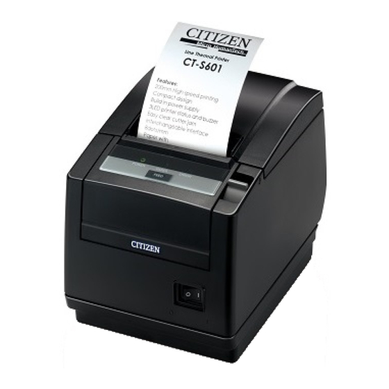
Citizen CT-S601 User Manual
Line thermal printer
Hide thumbs
Also See for CT-S601:
- User manual (220 pages) ,
- Specifications (2 pages) ,
- Command reference manual (454 pages)
Table of Contents
Advertisement
Advertisement
Table of Contents

Subscribe to Our Youtube Channel
Related Manuals for Citizen CT-S601


Summary of Contents for Citizen CT-S601
- Page 1 LINE THERMAL PRINTER MODEL CT-S601 User’s Manual...
- Page 2 WEEE MARK If you want to dispose of this product, do not mix it with general household waste. There is a separate collection systems for used electronics products in accordance with legislation under the WEEE Directive (Directive 2002/96/EC) and is effective only within European Union. Wenn Sie dieses Produkt entsorgen wollen, dann tun Sie dies bitte nicht zusammen mit dem Haushaltsmüll.
-
Page 3: Declaration Of Conformity
Declaration of Conformity This printer conforms to the following Standards: The Low Voltage Directive 2006/95/EC, the EMC Directive 2004/108/EC, the RoHS Directive 2002/95/EC, and the WEEE Directive 2002/96/EC. LVD : EN60950-1 EMC: EN55022 Class A EN61000-3-2 EN61000-3-3 EN55024 This declaration applies only to the 230-V model. IMPORTANT: This equipment generates, uses, and can radiate radio frequency energy and if not installed and used in accordance with the instruction manual, may cause interference to radio communications. -
Page 4: General Precautions
If you find omissions, errors, or have questions, please contact your Citizen Systems dealer. If you find any pages missing or out of order, contact your Citizen Systems dealer for a replacement. — 1 —... - Page 5 SAFETY PRECAUTIONS ...WHICH SHOULD BE STRICTLY OBSERVED Before using this product for the first time, carefully read these SAFETY PRECAUTIONS. Improper handling may result in accidents (fire, electric shock or injury). In order to prevent injury to operators, third parties, or damage to property, special warning symbols are used in the User’s Manual to indicate important items to be strictly observed.
- Page 6 • Dropping a metallic foreign object into the printer, may cause printer failure, fire, or electric shock. Should it occur, immediately turn the printer off, unplug it from the supply outlet, and call your local Citizen Systems dealer. Do not handle the printer in the following ways: Do not subject the printer to strong impacts or hard jolts (e.g., being...
- Page 7 CAUTION Do not use the printer under the following conditions. Avoid locations subject to vibration or instability. Avoid locations where the printer is not level. • The printer may fall and cause an injury. • The quality of printing may deteriorate. Do not obstruct the printer’s air vents.
- Page 8 • Neglecting these cautions may cause wires or insulation to break, which could result in electric leakage, electric shock, or printer failure. If the power cord sustains damage, contact your Citizen Systems dealer. Do not leave things around the electric outlet.
- Page 9 CAUTION Caution label is attached in the position shown in the following figure. Carefully read the handling precautions before using the printer. THIS LABEL INDICATES THE RISK OF BURNS DUE TO THE HIGH TEMPERATURE OF THE PRINT HEAD AND A RISK OF BEING CUT BY THE MANUAL AND AUTO CUTTERS WHILE THE PAPER COVER IS OPEN.
-
Page 10: Daily Maintenance
Do not touch any of the moving parts (e.g., paper cutter, gears, active electric parts) while the printer is working. In case of trouble do not attempt to repair the printer. Ask Citizen Systems service for repair. Be careful that the covers do not pinch your hands or fingers. -
Page 11: Table Of Contents
THE TABLE OF CONTENTS 1. GENERAL OUTLINE ..............9 1.1 Features................... 9 1.2 Unpacking..................10 1.3 Model Classification ..............10 1.4 Basic Specifications............... 11 2. EXPLANATION OF PRINTER PARTS ........12 2.1 Printer Appearance ................ 12 2.2 Inside the paper cover ..............15 2.3 Other Built-in Functions.............. -
Page 12: General Outline
1. GENERAL OUTLINE The CT-S601 line thermal printer series is designed for use with a broad array of terminal equipment including data, POS, and kitchen terminals. These printers have extensive features so they can be used in a wide range of applications. -
Page 13: Unpacking
1.2 Unpacking Make sure the following items are included with your printer. Printer: Quick Start Guide: Interface cover: AC adapter AC power cord: USB cable Power switch cover: 1 Notes: *1: CT-S601A only Sample paper roll: 1 roll *2: USB interface types only CD-ROM: In designated markets Quick Start... -
Page 14: Basic Specifications
1.4 Basic Specifications Item Specifications Model CT-S601 Print method Line thermal dot print method Print width 80 mm/640 dots, 72 mm/576 dots, 64 mm/512 dots, 54.5 mm/436 dots, 54 mm/432 dots, 52.5 mm/420 dots, 48 mm/384 dots, 45 mm/360 dots, 48.75 mm/390 dots, 68.25 mm/546 dots... -
Page 15: Explanation Of Printer Parts
*4: The 36AD2 is the AC adapter packaged as an accessory with the CT-S601A. The 36AD3 is the AC adapter built in to the CT-S601S. *5: Compliant if the Citizen Systems AC adapter (36AD2/36AD3) is used. 2. EXPLANATION OF PRINTER PARTS 2.1 Printer Appearance... - Page 16 Power switch Press this button to turn the power on or off. Maintenance cover Not used. Do not remove. CAUTION Do not open the maintenance cover. Operation panel PAPER LED POWER LED (green) ERROR LED (red) (orange) FEED button POWER LED (green) Lights when the power is on, turns off when the power is off.
- Page 17 Rear connectors Cash drawer Interface connector Power connector (AC adapter type) kick-out (serial, parallel, USB, etc.) connector AC inlet (built-in power supply type) Interface connector (serial, parallel, USB, etc.) Connects to the interface cable. The serial interface board is equipped with a DIP switch. Cash drawer kick-out connector Connects to the cable from the cash drawer.
-
Page 18: Inside The Paper Cover
2.2 Inside the paper cover Paper-end sensor (PE sensor) Platen Auto cutter Button to change paper near-end sensor Manual cutter Paper thickness Print head (thermal) selection lever Paper near-end sensor (PNE sensor) Platen Feeds the paper. Do not remove the platen except to do maintenance. Paper near-end sensor (PNE sensor) Detects when the paper is near the end of the roll. -
Page 19: Other Built-In Functions
Paper thickness selection lever Use this lever to select regular or thick paper according to the thickness of the paper being loaded. CAUTION Do not change the position of the paper thickness selection lever from the factory setting. 2.3 Other Built-in Functions Buzzer Buzzes when errors occur or when operations or command operations are performed. -
Page 20: Setup
3. SETUP 3.1 Connecting the AC Power Cord Turn off the power. For the built-in power type printer, connect the AC power cord to the AC inlet, and insert the plug into an electric outlet. For the AC adapter type printer, connect the cable connector of the AC adapter to the power connector. -
Page 21: Connecting Interface Cables
Always unplug the AC adapter from the printer before connecting the printer to a Powered USB interface. Failure to do so may damage the host PC. For information about installing a Powered USB interface, contact your Citizen Systems dealer. When disconnecting the cable, always hold the connector. -
Page 22: Connecting The Cash Drawer
Use a serial interface cable with the connection layout shown below. 25-pin - 25-pin cable 9-pin - 25-pin cable Printer Printer Signal Signal Signal Signal RXD 2 RXD 3 DSR 6 DSR 6 CAUTION Place the interface cable so people do not trip on it. 3.3 Connecting the Cash Drawer Turn off the power. - Page 23 (1) Connector pin configuration Signal Function Frame ground Connector used: TM5RJ3-66 (Hirose) or DRAWER1 Cash drawer 1 drive signal equivalent DRSW Cash drawer switch input Applicable connector: Cash drawer drive power supply TM3P-66P (Hirose) or equivalent DRAWER2 Cash drawer 2 drive signal Signal ground (common ground on circuits) (2) Electric characteristics...
-
Page 24: Precautions For Installing The Printer
3.4 Precautions for Installing the Printer The printer can be used horizontally, vertically, or installed on a wall. However, the CT-S601S (built-in power supply type) cannot be used vertically or installed on a wall. Use the optional stand for vertical applications, and the optional brackets for wall installations. -
Page 25: Partition For Paper Roll
3.5 Partition for Paper Roll Set the partition to the width of the paper roll you are loading. The partition is set at the factory to the position shown below. For 3-inch type: 80-mm wide paper roll For 2-inch type: 58-mm wide paper roll Turn off the power. -
Page 26: Setting The Dip Switch On The Serial Interface Board
3.6 Setting the DIP Switch on the Serial Interface Board Turn off the printer and unplug the power cord from the electric outlet. Remove the mounting screws of the serial interface board. Remove the serial interface board from the printer. Set the DIP switch according to the following table. -
Page 27: Adjusting The Paper Near-End Sensor
3.7 Adjusting the Paper Near-end Sensor Change the settings of the paper near-end sensor to set the position at which the near-end of the paper is detected. Use a pointed object, such as a pen, to gently press the button to change the paper near-end sensor. -
Page 28: Loading Paper
3.8 Loading Paper Press the cover open lever while the power is on. Open the paper cover. Load the paper roll so that the printable side of the paper is facing down, as shown by arrow A. Pull a few cm of paper straight out in the direction of arrow B. Close the paper cover in the direction of arrow C until you hear a click. -
Page 29: Attaching The Power Switch Cover
3.9 Attaching the Power Switch Cover Attach this cover to prevent the power switch from being used. Press the power switch cover onto the power switch compartment until it clicks. Power switch cover Put a screwdriver or other pointed object into the grooves on the power switch cover to remove it. -
Page 30: Attaching The Interface Cover
3.10 Attaching the Interface Cover Attach the interface cover to the back of the printer. The shape of the interface cover is different depending on the type of power source. Press the interface cover as shown in the diagram until you hear it click. CT-S601S 3.11 Removing the Interface Cover... -
Page 31: Maintenance And Troubleshooting
MAINTENANCE AND TROUBLESHOOTING 4.1 Periodic Cleaning A dirty print head or platen may reduce printing quality or cause malfunctions. Also, if paper dust collects on the sensor’s protective sheet, paper cannot be detected correctly. We recommend cleaning the printer periodically (every 2 to 3 months) as shown below. -
Page 32: Clearing A Cutter Lock (1)
4.2 Clearing a Cutter Lock (1) The ERROR LED flashes and the auto cutter blade remains extended because a foreign object or paper jam is obstructing it. If the ERROR LED is flashing, clear the locked cutter as shown below. Press the cover open lever while the power is on. -
Page 33: Clearing A Cutter Lock (2)
4.3 Clearing a Cutter Lock (2) The paper cover is designed to be opened if the cutter locks by pressing the cover open lever. If this does not open the paper cover, use the following procedure to clear the locked cutter. Turn off the printer and unplug the power cord from the electric outlet. -
Page 34: Self-Printing
The print head is hot immediately after printing. Do not touch it. Do not touch the print head with bare hands or metal objects. If the above procedure does not retract the auto cutter, contact your Citizen Systems dealer. 4.4 Self-printing While paper is loaded, press and hold the FEED button while turning the power on. -
Page 35: Hexadecimal Dump Printing
4.5 Hexadecimal Dump Printing Print received data in hexadecimal. If problems such as missing or duplicated data occur, this function allows you to check whether or not the printer is receiving data correctly. How to do hexadecimal dump printing Load paper. While the paper cover is open, press and hold the FEED button while turning the power on, and then close the paper cover. -
Page 36: Error Messages
4.6 Error Messages Paper-end The end of the roll of paper is detected at two stages, paper near-end and paper-end. When paper near-end is detected, the PAPER LED lights. Prepare a new paper roll. When paper end is detected, the PAPER LED and ERROR LED light. Load a new paper roll. - Page 37 The status display for various messages is shown below. POWER LED PAPER LED ERROR LED Status Buzzer (green) (orange) (red) Paper near-end Lights Lights — — Paper-end Lights Lights Lights Paper cover open or front cover Lights — Lights open Paper cover open or front cover Lights —...
-
Page 38: Other
5. OTHER 5.1 External Views and Dimensions (Unit: mm) Built-in power supply type AC adapter type — 35 —... -
Page 39: Printing Paper
5.2 Printing Paper Use the paper shown in the following table or paper of the same quality. Paper type Product name Recommended TF50KS-E2D from Nippon Paper paper roll PD150R or PD160R from Ohji Paper PA220AG, HP220A, HP220AB-1, F230AA, P220AB, or PB670 (2-color paper) from Mitsubishi Paper (Unit: mm) Printable side... -
Page 40: Manual Setting Of Memory Switches
5.3 Manual Setting of Memory Switches Memory switches are used to set various printer settings. The memory switches can be set manually (set by hand on the printer) or by commands. This section explains how to perform manual settings. For information on how to set the memory switches using commands, please refer to the Command Reference. -
Page 41: Individual Setting Mode
MSW3-7 MSW8-1 MSW6-2 Paper Character Manufacturer Model Full Col CBM1000 Print Character width space Print Mode Width Space CITIZEN CBM1000 58 mm — Auto Valid 432dots — linefeed 80 mm — Auto Valid 576dots — linefeed CT-S300 58 mm —... -
Page 42: Memory Switch Initialization
Press the FEED button for at least two seconds. A setting for the memory switch is printed, through the cycle, each time the FEED button is pressed for at least two seconds. Press the FEED button for at least two seconds to cycle through the list until the function of the memory switch you want to change is printed. - Page 43 The function of each memory switch is shown in the following table. (Shaded values are factory settings.) Switch no. Function MSW1-1 Power ON Info Valid Not Send MSW1-2 Buffer Size 4K bytes 45 bytes MSW1-3 Busy Condition Full/Err Full MSW1-4 Receive Error Print“?”...
- Page 44 Switch no. Function MSW6-1 Act. For Driver Invalid Valid MSW6-2 Character Space Invalid Valid MSW6-3 Reserved Fixed — MSW6-4 Reserved Fixed — MSW6-5 Reserved Fixed — MSW6-6 Reserved Fixed — MSW6-7 Reserved Fixed — MSW6-8 Reserved Fixed — Switch no. Function Initial setting Setting value...
- Page 45 Note: *1: If print data is very dense, the print head is hot, data transmission is slow, or some other conditions, the motor and printing may occasionally stop which causes white stripes in the printout. To print high-density data, set MSW2-3 (Spool Print) to ON to reduce striping, although this increases the time before printing starts.
- Page 46 TZ74916-01F A68223E-1403 March 2014...
Need help?
Do you have a question about the CT-S601 and is the answer not in the manual?
Questions and answers