Table of Contents
Advertisement
Advertisement
Table of Contents

Related Manuals for LG FFH-286A


Summary of Contents for LG FFH-286A
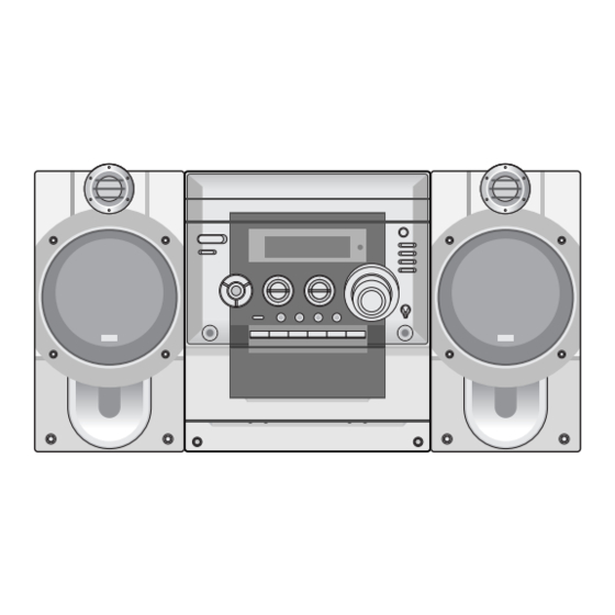
- Page 1 3CD CHANGER HI-FI SYSTEM SERVICE MANUAL MODEL : FFH-286A/AD, FE-286E...
-
Page 2: Table Of Contents
CONTENTS SECTION 1. GENERAL • SERVICING PRECAUTIONS ........................1-2 • ESD PRECAUTIONS ..........................1-4 • SPECIFICATIONS ............................. 1-5 SECTION 2. ELECTRICAL • ADJUSTMENTS ............................2-1 • TROUBLESHOOTING ..........................2-3 • WAVEFORMS OF MAJOR CHECK POINT ....................2-7 • BLOCK DIAGRAM ........................... 2-17 •... -
Page 3: Section 1. General
SECTION 1. GENERAL SERVICING PRECAUTIONS NOTES REGARDING HANDLING OF THE PICK-UP 1. Notes for transport and storage 1) The pick-up should always be left in its conductive bag until immediately prior to use. 2) The pick-up should never be subjected to external pressure or impact. Storage in conductive bag Drop impact 2. - Page 4 NOTES REGARDING COMPACT DISC PLAYER REPAIRS 1. Preparations 1) Compact disc players incorporate a great many ICs as well as the pick-up (laser diode). These components are sensitive to, and easily affected by, static electricity. If such static electricity is high voltage, components can be damaged, and for that reason components should be handled with care.
-
Page 5: Esd Precautions
ESD PRECAUTIONS Electrostatically Sensitive Devices (ESD) Some semiconductor (solid state) devices can be damaged easily by static electricity. Such components commonly are called Electrostatically Sensitive Devices (ESD). Examples of typical ESD devices are integrated circuits and some field-effect transistors and semiconductor chip components. The following techniques should be used to help reduce the incidence of component damage caused by static electricity. -
Page 6: Specifications
SPECIFICATIONS SECTION MODEL FFH-286A/AD General Power supply Refer to the back panel of the unit Power consumption Mass 5.70kg Extemal dimensions(W 360mm Frequency Response 40-18000Hz Signal-to-noise ratio 70dB Dynamic range 70dB Tuning Range 87.5-108.0MHz or 65-74MHz, 87.5-108.0MHz Intermediate Frequency 10.7 MHz... - Page 7 MEMO - 1-6 -...
-
Page 8: Section 2. Electrical
SECTION 2. ELECTRICAL ADJUSTMENTS This set has been aligned at the factory and normally will not require further adjustment. As a result, it is not recommended that any attempt is made to modificate any circuit. If any parts are replaced or if anyone tampers with the adjustment, realignment may be necessary. -
Page 9: Tuner Adjustment
3. RECORD BIAS ADJUSTMENT Deck Mode Test Tape Test Point Adjustment Adjust for ERASE HEAD 60kHz±5kHz (Auto stop) Rec/Pause MTT-5511 L203 WIRE(PN202) 85kHz±5kHz(Auto Reverse) Record/Playback PN202 Frequency Counter Head and Pause Mode Test Tape Unit MTT-5511 Record/Playback head Figure 3. Record Bias Adjustment Connection Diagram 4. -
Page 10: Troubleshooting
TROUBLESHOOTING Turn power on. Check power supply circuit. PN807 PIN5, 6.2V Is power on? PN807 PIN7, 5V IC803 PIN 2, 3.3V Check the connector Check the DISK turns Does initial read work? PN801, PN802, PN809 Check the Laser Check the focus circuit Check the TRAKING circuit Check the tracking servo circuit. - Page 11 Fails to initial read Check the Voltage change of PN 809 Defective connector Disc motor turns PIN20(OPEN, CLOSE) PN809 Does RF waveform appear? Check the Data transmission from Defective connector IC801 Pin3 PN809 pin11 to CD DSP PN809, Defective MICOM Check the Data transmission from Defective connector PN809 pin13 to MICOM...
- Page 12 Laser does not light. Is “3.5V” applied to pin of IC 801? Did pickup return to Is data transferred from Defective MICOM. innermost circular? MICOM IC ? Does voltage appear at IC 802 pin 17, 18? Defective IC 801, 802 Defective slide motor and/or connector.
- Page 13 Laser lights Does lens move up/down? Defective IC801 Check the signal of FOCUS SEARCH (IC801 Pin 21) Defective IC802 Chekc the signal of PN802 pin 13, 14 Open activator and/or connector Does FE signal appear? (IC801 pin 13) Defective IC801 Degraded laser diode Does DRF signal appear? (IC 801 pin67) Defective PICK-UP...
-
Page 14: Waveforms Of Major Check Point
WAVEFORMS OF MAJOR CHECK POINT 1. HF signal (RF signal ) waveform 2. EFM signal (IC801 pin 3)waveform (IC801 pin 3) during normal play during Normal Play 0.5V/Div. 0.5V/Div. 500nS/Div. 5µS/Div. 3. Focus coil drive waveform(IC802 pin13) • Focus coil drive waveform(FDO: IC801 pin21) and •... - Page 15 P-SENS PART Does +5V appear at ZD701? Check the waveform of D713(Cathod). Replace the D713 Check the pattern of Check the 5.6K of R714 and IC301 Pin replace ZD703(5.1V) VKK PART Does DC - 33V appear at CN302 Pin Dose -33V appear at ZD704(-) Replace the ZD704(-33V)
- Page 16 Power Circuit Check the Fuse Replace the Fuse Check the AC output of Check the DC output Check the power Ass’y or C736 CN701 Pin4, 5 Replace the Transformer Replace the D745, D746, D747, D748 Check the DC Output of C738 Check the AC Output of CN701 PIN 1, 3 Check the power Ass’y or...
- Page 17 Muting circuit (MUTE) Dose “High” appear at Q712 “E” Check the “High” of Q712 “C” check the “High” Q721, Q771, “B” Replace the TR MUTE Audio abnormal Check the output of IC701 Pin 26, 27 Refer to “IC701 Troubleshooting” Check the input of IC702 Pin 2,4 (L-CH/R-CH) Refer to “Muting Troubleshooting”...
- Page 18 FUNCTION MODE Audio abnormal TAPE Check the signal input of IC401 pin 28, 37 Chekc the signal input of IC401, pin 29, 36 Refer to “IC202 Troubleshooting” Check the signal input of JK401 Tuner Check the signal input of IC401 pin 31, 34 Check the signal input of IC401 pin 30, 35 Check the signal of CN513 Pin 1, 3 or Refer to “IC102 Troubleshooting”...
- Page 19 IC301 Troubleshooting Check the power supplying IC301 Pin 17, 46, 90? Refer to “Power Circuit Troubleshooting” Check the 5V of IC301 pin26 Check the P-SENS Check the oscillation of X301 Replace the X301 When power supplying to IC301 pin17. (High ➞ Low ➞ High) Check the RESET circuit Replace the IC301 IC203 Troubleshooting...
- Page 20 IC401 Troubleshooting Check the power of IC401 Pin29. Check the Pulse of IC401 Pin21,22 Check the IC301 Pin85,86,75,76 Refer to “IC301 Check the signal output of IC401 Pin 32,33 Troubleshooting” Check the PATTERN of MICOM (85,86) IC401 Pin 21,22 Replace the IC401 Check the Signal output of pin25, 24 Replace the IC401 FM (TUN101)
- Page 21 IC102 Troubleshooting Is power supplied to pin8(10V) Refer to “Power Circuit Troubleshooting” Check the waveform of Pin 20, 21 Check the FM(TUN101) & AM(L107) Replace the IC102 Check the output of Pin 16, 17 Check the “Low” of Pin 13 Refer to “IC103 Troubleshooting”...
- Page 22 AM•COIL Troubleshooting Check the “High” of L107 Pin 2 Refer to “IC103 Troubleshooting” Check the oscillation of L107 Pin 13 Replace the L107 Refer to “IC102 Troubleshooting” Play Check the VCC supplying to IC202 pin 18 Refer to “Power Circuit Troubleshooting” Check the signal output of IC202 pin 5, 20 Check the Deck Mecha Replace the Deck...
- Page 23 REC (Q252, Q202 ON / R273, R223 High) Check signal supplied to IC202 pin 11, 14? Check the “Low” of Q253, Q203 “B” Refer to “IC203 Troubleshooting” Replace the Q253, Q203 Check the output of IC202 Pin9, 16 Check the Vcc power of IC202 Pin18 Check the IC201 pin6 : 12V and pin 4 : High Check the power or Refer to “IC203 Troubleshooting”...
-
Page 24: Block Diagram
BLOCK DIAGRAM NOTE: Warning NOTE: Parts that are shaded are critical With respect 1. Shaded(■) parts are critical for safety.Replace only to risk of fire or electrical shock. with specified part number. 2. Voltages are DC-measured with a digital voltmefer during Play mode. -
Page 25: Schematic Diagrams
SCHEMATIC DIAGRAMS • MAIN SCHEMATIC DIAGRAM NOTE: Warning NOTE: Parts that are shaded are critical With respect 1. Shaded(■) parts are critical for safety.Replace only to risk of fire or electrical shock. with specified part number. 2. Voltages are DC-measured with a digital voltmefer during Play mode. - Page 26 • FRONT SCHEMATIC DIAGRAM 2-21 2-22...
- Page 27 • TUNER/DECK SCHEMATIC DIAGRAM 2-23 2-24...
- Page 28 • CDP SCHEMATIC DIAGRAM 2-25 2-26...
-
Page 29: Wiring Diagram
WIRING DIAGRAM NOTE: Warning Parts that are shaded are critical With respect to risk of fire or electrical shock. 2-27 2-28... -
Page 30: Printed Circuit Diargams
PRINTED CIRCUIT DIAGRAMS • MAIN P.C. BOARD (SOLDER SIDE) 2-29 2-30... - Page 31 • MAIN P.C. BOARD (COMPONENT SIDE) 2-31 2-32...
- Page 32 • FRONT P.C. BOARD(COMPONENT SIDE) 2-33 2-34...
- Page 33 • FRONT P.C. BOARD(SOLDER SIDE) 2-35 2-36...
- Page 34 • CD MAIN P.C. BOARD • AMP & POWER P.C. BOARD NOTE: Warning Parts that are shaded are critical With respect to risk of fire or electrical shock. - 2-37 -...
-
Page 35: Internal Block Diagram Of Ics
INTERNAL BLOCK DIAGRAM OF ICs ■ FAN8039BD3 5-CH Motor Diver Description The FAN8039BD3 is a monolithic integrated circuit suitable for a 5-CH motor driver which drives the tracking actuator, focus actuator, sled motor, tray motor, spindle motor of the DVDP/CAR-CD systems. (GND) PS RESX FUNCTION... - Page 36 ■ KA78R33 Low Dropout Voltage Regulator Description The KA78R33 is a low-dropout voltage regulator suitable for various electronic equipments. It provides constant voltage power source with TO-220 4 lead full mold package. Dropout voltage of KA78R33 is below 0.5V in full rated current(1A). This regulator has various function such as peak current protection, thermal shut down, overvoltage protection and output disable function.
- Page 37 Block Diagram PHASE DETECTOR REFERENCE DIVIDER CHARGE PUMP XOUT SWALLOW COUNTER UNLOCK FMIN AOUT 1/16. 1/17 4bits DETECTOR 12bits PROGRAMMABLE AMIN DIVIDER DATA SHIFT REGISTER UNIVERSAL IFIN LATCH COUNTER POWER RESET ■ LA1837 Single-Chip Home stereo IC with Electronic Tuning Support The LA1837 is a single-chip AM/FM IF and MPX IC that supports electronic tuning and was developed for use in home stereo systems.
- Page 38 ■ KIA 78R12 PI 4 TERMINAL LOW DROP VOLTAGE REGULATOR The KIA78RXX Series are Low Drop Voltage Regulator suitable for various electronic equipments. It provides constant voltage power source with TO-220 4 termainal lead full molded PKG. The Regulator has multi function such as over current protection, overheat protection and ON/OFF control.
- Page 39 Block Diagram ■ KIA7805AP/API THREE TERMINAL POSITIVE VOLTAGE REGULATORS 5V, 6V, 8V, 9V, 10V, 12, 15V, 18V, 24V. EQUIVALENT CIRCUIT - 2-42 -...
- Page 40 ■ BA3126N 2-channel head switch for radio cassette recorders - 2-43 -...
- Page 41 ■ BU2090F 12-bit, Serial IN, Parallel OUT driver Block diagram Control circuit DATA 12-bit shift register CLOCK Latch Output buffer (open drain) PIN DESCRIPTION Pin No. Pin name Function BU2090/F/FS BU2092/F BU2092/FV DATA Serial data input CLOCK Data shift clock input Data latch clock input parallel data output parallel data output...
-
Page 42: Repairs Regarding Cd Mechanism
REPAIRS REGARDING CD MECHANISM IMPROVED METHOD - WHEN THE TRAY GEARS WERE DISTORTED 1. How to open the tray. In case of not suppling power push two hooks (H) of the base, and them open the tray. 2. How to improve the distorted gears. (1) Do the hole "C"... - Page 43 MEMO - 2-46 -...
-
Page 44: Section 3. Exploded Views
SECTION 3. EXPLODED VIEWS NOTE) Refer to “SECTION 5 REPLACEMENT PARTS LIST” in order to look for the • CABINET AND MAIN FRAME SECTION part number of each part. (Option) (Option) -
Page 45: Tape Deck Mechanism: Auto Stop Deck(Optional)
• TAPE DECK MECHANISM: AUTO STOP DECK(OPTIONAL) -
Page 46: Tape Deck Mechanism: Auto Reverse Deck
• TAPE DECK MECHANISM: AUTO REVERSE DECK... -
Page 47: Cd Mechanism
• CD MECHANISM... -
Page 48: Section 4. Speaker
SECTION 4. SPEAKER SECTION MODEL: FE-286E - 4-1 -... - Page 49 MEMO - 4-2 -...
Need help?
Do you have a question about the FFH-286A and is the answer not in the manual?
Questions and answers