Table of Contents
Advertisement
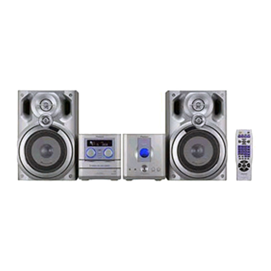
STEREO CD TUNER
XC-LA21
THIS MANUAL IS APPLICABLE TO THE FOLLOWING MODEL(S) AND TYPE(S).
Model
Type
XC-LA21
DBDXCN
DDXCN/AR
¶ System Component Table
Component
COMPACT MINI COMPONENT
STEREO CD TUNER
STEREO POWER AMPLIFIER
SPEAKER SYSTEM
CONTENTS
1. SAFETY INFORMATION ....................................... 2
2. EXPLODED VIEWS AND PARTS LIST ................. 4
4. PCB CONNECTION DIAGRAM ........................... 20
5. PCB PARTS LIST ................................................ 30
6. ADJUSTMENT ..................................................... 33
PIONEER CORPORATION
PIONEER ELECTRONICS SERVICE, INC. P.O. Box 1760, Long Beach, CA 90801-1760, U.S.A.
PIONEER EUROPE NV Haven 1087, Keetberglaan 1, 9120 Melsele, Belgium
PIONEER ELECTRONICS ASIACENTRE PTE. LTD. 253 Alexandra Road, #04-01, Singapore 159936
c
PIONEER CORPORATION 2000
3 COMPACT DISC MULTI CHANGER
Power Requirement
AC110-127V/220-230/240V
AC110-127V/220-230/240V
Model
X-LA21
XC-LA21
M-LA21
S-LA21
4-1, Meguro 1-chome, Meguro-ku, Tokyo 153-8654, Japan
LA21
STEREO CD TUNER
The voltage can be converted by
the following method.
With the voltage selector
With the voltage selector
Service manual
RRV2370
RRV2392
This manual.
RRV2393
RRV2394
7. GENERAL INFORMATION ................................ 37
7.1 DIAGNOSIS .................................................. 37
7.1.1 TROUBLE SHOOTING ........................ 37
7.1.2 DISASSEMBLY/ASSEMBLY ................ 41
7.2 PARTS .......................................................... 49
7.2.1 IC .......................................................... 49
7.2.2 DISPLAY ............................................... 51
7.3 REMOTE CONTROL UNIT .......................... 52
ORDER NO.
RRV2392
Remarks
T – IZK OCT. 2000 Printed in Japan
Advertisement
Table of Contents
Troubleshooting

Related Manuals for Pioneer XC-LA21


Summary of Contents for Pioneer XC-LA21
- Page 1 PIONEER CORPORATION 4-1, Meguro 1-chome, Meguro-ku, Tokyo 153-8654, Japan PIONEER ELECTRONICS SERVICE, INC. P.O. Box 1760, Long Beach, CA 90801-1760, U.S.A. PIONEER EUROPE NV Haven 1087, Keetberglaan 1, 9120 Melsele, Belgium PIONEER ELECTRONICS ASIACENTRE PTE. LTD. 253 Alexandra Road, #04-01, Singapore 159936 PIONEER CORPORATION 2000 T –...
-
Page 2: Safety Information
LABEL CHECK IMPORTANT THIS PIONEER APPARATUS CONTAINS LASER OF CLASS 1. SERVICING OPERATION OF THE APPARATUS S H O U L D B E D O N E B Y A S P E C I A L L Y INSTRUCTED PERSON. -
Page 3: Exploded Views And Parts List
XC-LA21 2. EXPLODED VIEWS AND PARTS LIST NOTES: Parts marked by "NSP" are generally unavailable because they are not in our Master Spare Parts List. mark found on some component parts indicates the importance of the safety factor of the part. -
Page 4: Exterior Section
XC-LA21 2.2 EXTERIOR SECTION DDXCN/AR Only 26,61 DDXCN/AR Only Refer to section "2.3 CD MECHA. SECTION". - Page 5 GND. Copper Plate B 650PMT141000 Side Panel-R 600PMT118002 Ferrite Core 032219180000 Bottom Tray 600PMT121000 (2) CONTRAST TABLE XC-LA21/DBDXCN and DDXCN/AR are constructed the same except for the following : Part No. Mark No. Symbol and Description XC-LA21 XC-LA21 Remarks /DBDXCN /DDXCN/AR...
- Page 6 XC-LA21 2.3 CD MECHA. SECTION 14 12...
- Page 7 XC-LA21 CD MECHA. SECTION PARTS LIST Mark No. Description Part No. Mark No. Description Part No. Assy Chassis 45-093-4256 Assy Motor DRW S 45-093-4239 Drawer 2 45-264-3278 Spring 01-080-4541 Spring 01-082-4643 Assy Holder L 45-093-3241 Assy Holder R3B 45-093-3296 Spring...
-
Page 8: Block Diagram And Schematic Diagram
XC-LA21 3. BLOCK DIAGRAM AND SCHEMATIC DIAGRAM 3.1 BLOCK DIAGRAM STD. TUNER ASSY CD MECHA. PICKUP ASSY Spindle Carriage Drawer Motor Motor Motor FE101 CN102 (FM) (16P) (FM) ANTENNA CN101 (16P) (6P) T101 T103 (AM) (AM) TA2092N TA7291S TA7291S DRIVER... - Page 9 XC-LA21 CN20 (6P) M-LA21 (PH) L-CH PHONES R-CH JK503 CN604 From CN22 SN602 WH602 LK501 (7P) XC-LA21 (8P) (8P) (4P) (4P) : AUDIO SIGNAL ROUTE (RF/CD) : AUDIO SIGNAL ROUTE (TUNER) SPEAKER (AM) : AUDIO SIGNAL ROUTE (AM) IC504 IC601...
- Page 10 XC-LA21 3.2 OVERALL WIRING DIAGRAM PICKUP ASSY 1 2 3 4 5 6 7 8 9 10 11 12 13 14 15 16 AM ANT FM ANT 3 4 5 6 7 8 9 10 11 12 13 14 15 16...
- Page 11 XC-LA21 Note : When ordering service parts, be sure to refer to "EXPLODED VIEWS and PARTS LIST" or "PCB PARTS LIST". J905 AUX ASSY AUX IN To M-LA21 (PMT1LA100091) To M-LA21 AUX OUT J201 CN204 1 2 3 4 5 6 7 8 9 10 11 12 13...
- Page 12 XC-LA21 3.3 STD. TUNER ASSY 118-040102-002A 042-104511-000A (AM) (FM) 118-040102-002A (FM) 136-14PMT1-B00J 003-020280-050 (AM) (FM) (FM) 008-314170-008A 019-000107-006A 003-050010-050 012-007840-010A (AM) 012-006120-010A 135-006116-160J 005-035100-000A (AM) 007-200610-000A (AM) 003-020380-050 008-685500-000A 136-TOCB17-171J CN201 136-03PMT1-B00J 010-849257-001A 009-607200-000A 003-024010-050 136-FEBTVK-240J 135-006232-300J...
- Page 13 XC-LA21 003-020380-050 019-000107-006A (FM) (FM) 003-082110-050 012-000120-010A (AM) 003-020380-050 003-020280-050 003-020280-050 010-101837-000A (FM) (AM) 003-020380-050 012-002240-010A 019-000450-012A 003-020380-050 003-020280-050 012-7NF803-007A 003-020380-050 018-010014-000A 003-020380-050 008-685500-000A 011-010051-120A : AUDIO SIGNAL ROUTE (RF/CD) : TUNER SIGNAL ROUTE (AM) STD. TUNER ASSY : TUNER SIGNAL ROUTE (AM)
- Page 14 XC-LA21 3.4 CD ASSY 003-624052-050A 003-624052-050A 037-003534-100 020-001693-000A 010-849284-000A Decorder 135-006232-301J 008-680500-000A 011-010056-120A 136-08PMT1-250J...
- Page 15 XC-LA21 CD ASSY (CD--PMT1E) 018-010014-000A 008-685500-000A 003-624052-050A 002-104085-102A 002-104085-102A VREF 135-TOCA16-160A 002-472065-000A RF Amp. 010-832065-000A 002-104085-102A 136-067238-205J 010-832065-000A 136-04PMT1-250J CARRIAGE MOTOR : AUDIO SIGNAL ROUTE (RF/CD) DRAWER MOTOR...
- Page 16 XC-LA21 3.5 AUDIO, AUX, RECT and TRANS ASSYS CN13 CN206 135-PHS030-030J 135-006116-160J 004-010310-100 004-068350-100 Selector 004-068350-100 004-010310-100 (AU) AUDIO ASSY (PMT101000210) CN904 010-400009-001A 008-801144-000A 120-100470-000 9V Reg. 050-140060-200J 008-685500-000A (AU) (AU) (AU) 003-020380-050 J904 118-000244-000A 011-010240-120A 135-2001WS-140J 008-801144-000A 008-801144-000A (AU)
- Page 17 XC-LA21 011-010051-121A : AUDIO SIGNAL ROUTE (RF/CD) : TUNER SIGNAL ROUTE (AU) : AUDIO SIGNAL ROUTE (AUX) 011-024001-000A NOTE FOR FUSE REPLACEMENT FOR CONTINUED PROTECTION AGAINST RISK OF FIRE. CAUTION - 135-005267-090J REPLACE WITH SAME TYPE AND RATINGS ONLY. RECT ASSY...
- Page 18 XC-LA21 3.6 DISPLAY/CTL ASSY DISPLAY/CTL ASSY (PMT101000041) 110-033045-013A 135-FESTVK-240J 110-033045-013A 110-033045-013A 006-747300-05CA 001-229103-000A 003-H12203-204A 110-033040-013A 135-TOCB17-171J 021-114165-000A 110-033162-003A...
- Page 19 XC-LA21 115-000920-000A 001-220104-000A 001-220104-000A SYSTEM CONTROL IC 111-000638-000A 001-220104-000A 003-430050-050 DISPLAY/CTL ASSY S401 : STOP 7 S402 : PLAY 3 8 S403 : BASS/TREBLE S404 : STANDBY/ON S405 : ENTER S406 : TIMER S407 : DISPLAY/CLOCK S408 : 4 / 1 / TUNING –...
-
Page 20: Pcb Connection Diagram
XC-LA21 4. PCB CONNECTION DIAGRAM NOTE FOR PCB DIAGRAMS : Part numbers in PCB diagrams match those in the schematic diagrams. The parts mounted on this PCB include all necessary parts for several destinations. For further information for respective destinations, be sure to check with the schematic diagram. - Page 21 XC-LA21 R182 T105 T106 C156 W245 C144 C180 FE101 L107 R151 C187 C125 C185 C157 R153 IC101 C142 R124 R150 W246 C126 C128 C170 C105 C167 C127 R129 R166 C140 W226 C129 C166 R128 R165 C137 R125 C186 C131 R167...
- Page 22 XC-LA21 4.2 CD ASSY CD ASSY CD MECHA. CD+9V GNDM GNDM VREF GNDCD CARRIAGE MOTOR, PICKUP DRAWER GNDCD ASSY CD+5V MOTOR GNDCD GNDCD SERVO BOARD GNDCD PMT-1-01-03 CD+9V DRAW+ GNDM DRAW- CARR- CARR+ CD+9V BLACK GNDCD CD MECHA. SIDE A...
- Page 23 XC-LA21 CD ASSY CD+9V GNDM GNDM GNDCD 48 45 GNDCD CD+5V GNDCD GNDCD SERVO BOARD GNDCD PMT-1-01-03 CD+9V GNDM DRAW+ DRAW- CARR- CARR+ CD+5V CD+9V GNDCD SIDE B...
- Page 24 XC-LA21 4.3 AUDIO ASSY C270 R292 W252 W258 AUDIO ASSY W259 R290 SN204 CN204 R229 PWRCTRL W201 PMT1-01-02 AGND W209 W213 DGND DGND R220 +31V PGND IC202 -31V C281 C233 D201 C212 C262 IC201 W214 C203 W212 AGND C223 C224...
- Page 25 XC-LA21 CN207 R255 C269 C270 C268 C267 C259 R278 Q265 R271 C280 R279 R280 R281 R269 R266 C264 R272 C265 CN204 R249 R265 RCTRL R259 C261 R251 L253 C262 RL251 R287 R295 C276 R296 R288 L201 CN203 CN206 SPCTL D254...
- Page 26 XC-LA21 4.4 RECT and TRANS ASSYS CN11 RECT ASSY PMT1LA-01-06 RECTIFIER BOARD +TUNER8V +CD8V W318 +M8V +MCU8V P CLT D306 CLK CLT PRIMAR AC 3.8V C302 AC 3.8V RELAY B+ RELAY B+ D310 D307 -24V DANGER W302 D GND MCU AC GND...
- Page 27 XC-LA21 TRANS ASSY YEL. ORN. PRIMARY TF303 SW301 SW302 DANGER PMT1LA-01-07 TRANSFORMER BOARD W307 W306 C316 RL301 R308 F306 D311 AC IN SIDE A...
- Page 28 XC-LA21 4.5 AUX ASSY AUX ASSY C920 R937 R910 C905 R909 R905 R903 IC901 Q903 D902 R908 CN203 C902 CN204 R911 R914 R912 PWRCTL W913 R901 Q902 R917 R944 R942 R916 C926 C901 J905 Q912 AGND R940 W902 W912 AGND...
- Page 29 XC-LA21 4.6 DISPLAY/CTL ASSY DISPLAY/CTL ASSY Q403 Q405 Q402 Q405 R439 S408 S409 DOWN S412 S415 LED401 DISC1 DISC1E LED412 S404 R401 R441 R402 S401 POWER Q403 S411 S414 LED402 STOP DISC2 DISC2E SN15 R403 R428 R429 R440 W435 R437...
-
Page 30: Pcb Parts List
XC-LA21 Mark No. Description Part No. Mark No. Description Part No. 5. PCB PARTS LIST NOTES: Parts marked by "NSP" are generally unavailable because they are not in our Master Spare Parts List. mark found on some component parts indicates the importance of the safety factor of the part. - Page 31 XC-LA21 Mark No. Description Part No. Mark No. Description Part No. Q2 (TRLNPNPWR 3DA8050) 008-680500-000A Q1 (TRLPNPPWR 3CA8550) 008-685500-000A AUDIO ASSY 2SB562 2SC1815 SEMICONDUCTORS D1-D3 1N4148 IC201 BU4052BC Z1 (ZENER IN-5232B 5.6V) 011-010056-120A IC202 BH3854FS Q201 2SC1815 COILS D201 MTZJ4.7B...
- Page 32 XC-LA21 Mark No. Description Part No. Mark No. Description Part No. OTHERS OTHERS CONN PIN 3 PINS 050-030160-200J JP WIRE AWG22#UL1672 051-265160-003J J201 CONN PIN 14 PINS 050-140060-200J JP WIRE AWG22 YELLOW 051-265180-010J JP WIRE AWG22 140MM 051-275140-009J AC CONTACT TERMINAL...
-
Page 33: Adjustment
XC-LA21 6. ADJUSTMENT 6.1 CD SECTION CD ASSY is taken out according to the procedure of DISASSEMBLY. And, please adjust the part CD after connecting connectors. 6.1.1 PREPARATIONS (1) Jigs and Measuring Instruments CD TEST DISC screwdriver Precise screwdriver (YEDS-7) - Page 34 XC-LA21 6.1.2 Adjustment (1) Adjustment Locations CD ASSY SIDE A CD+9V GNDM GNDM (FOCUS OFFSET) VREF VREF (FOCUS BALANCE) GNDCD (TRACKING BALANCE) GNDCD CD+5V GNDCD GNDCD (TRACKING OFFSET) O BOARD GNDCD Fig. 1 Adjustment Locations...
- Page 35 XC-LA21 (2) Check and Adjustment 1. Focus Offset (FEO) Adjustment FUNCTION : CD DC voltage 10 mV CD in stop mode Focus Offset Oscilloscope DC Mode V : 50mV/div H : 1mSec/div START Player Probe VREF CD ASSY 2. Tracking Offset (TEO) Adjustment...
- Page 36 XC-LA21 3. Tracking Balance (TEB) Adjustment FUNCTION : CD (VREF) Keeps pushing the FF button. Track No. 1 of YEDS-7 TEST DISC PLAY Tracking Balance VC is made a center. A : B symmetry ADJ Oscilloscope DC Mode V : 100mV/div...
-
Page 37: General Information
XC-LA21 7.1 GENERAL INFORMATION 7.1 DIAGNOSIS 7.1.1 TROUBLE SHOOTING 1. Troubleshooting 2. Cannot hear the sound of relay when power cord plug in Please Plug in POWER cord Can you hear the sound of Relay ? Is Power Supply of 5V... - Page 38 XC-LA21 3. Can you hear the sound of CD Changer 4. Tuner troubleshooting Mechanism or clamper movement when power cord plug in Are the pin 2 of IC5 and Have noise come out ? IC6 have 8V supply ? Check the corresponding 8V power supply.
- Page 39 XC-LA21 5. CD troubleshooting • The total track number is incorrectly displayed Is MECHA ERROR displayed ? Do the CD head sled to the inner ? Please check 3P, 4P of CN4 and 9P, 11P of IC3. Open the CD tray by pressing "CD1/2/3 EJECT".
- Page 40 XC-LA21 6. No audio signal come out on speaker Check the pins 9 (B) and 10 (A) of the IC201. Is the value is corrected according to Table 1 Please check the corres- ponding circuit and connec- tion. Do the corresponding Audio input...
-
Page 41: Disassembly/Assembly
XC-LA21 7.1.2 DISASSEMBLY/ASSEMBLY (1) Main Body Section STANDBY/ON OPEN/CLOSE Flat Blade Screwdriver Unook Tray Panel Set Drawer Side Panel L (Remove as well as Side Panel R) Unook Unhook Front Unit Unook Remove Side Panel R by sliding to a rear side. - Page 42 XC-LA21 (2) CD MECHA. CAUTION If Tray Panel Set is not detached when the CD MECHA. is repaired, the CD MECHA. cannot be removed from the main body of the product. When Drawer was not able not to open and shut by some something wrong's (The power supply does not enter, etc.)
- Page 43 XC-LA21 Caution for Disassembly/Assembly of CD MECHA. 1. As for the distinction method of Carriage100, 200, and 300, Switch distinguishes the shape of the projection part on its back. 2. Please do not disassemble Assy Holder L, R and the inside of...
- Page 44 XC-LA21 Drawer Disassembly of Ass'y Motor CRG S and Ass'y Motor DRW S Bottom Side Ass'y Motor CRG S Ass'y PC Board A Drawer Ass'y Motor DRW S Belt Belt Disconnect the Hook...
- Page 45 XC-LA21 Chassis Lever 2 Carriage 300 Bottom Side Lift up The loss of this gear is noted. Arm Stopper B Spring Ass'y Clamper S0 Disconnect the Hook Lifter Lifter Spring Belt Spring Ass'y Slider 2 Hook...
- Page 46 XC-LA21 Disassembly of Carriage 100, 200 The loss of Bevel Gear is noted. Slider 1 Drawer Carriage 100 Carriage 200 The back of Drawer Hook Assembly of Carriage 100, 200 Hooks (Carriage 100 is No.1 carriage. Carriage 200 is No.2 carriage.)
- Page 47 XC-LA21 Notes of procedure FRONT side Hang Carriage only here of Pinion. Carriage 200 is lightly lifted by the finger. When Carriage 100 drops below, Carriage 200 is lightly lifted by the finger. Note : Lift it horizontally when you lift Carriage.
- Page 48 XC-LA21 Assembly of Drawer and Chassis Its right side is slowly lowered up to the angle by which Bevel The following work is done before Drawer is put on Chassis. Gear can do in the slide while doing Drawer back and forth by (1) It is confirmed that Carriage 300 is clamped, and Clamper has about 5mm.
-
Page 49: Parts
XC-LA21 7.2 PARTS 7.2.1 IC • The information shown in the list is basic information and may not correspond exactly to that shown in the schematic diagrams. LC876564 (DISPLAY/CTL ASSY : IC401) • System Control IC Pin Function l l o... - Page 50 XC-LA21 l l o l l o l l o l l o l l o l l o l l o l l o l l o l l o d i l t i s c t i...
-
Page 51: Display
XC-LA21 7.2.2 DISPLAY 115-000920-000A (HNA-09SS20) (DISPLAY CONTROL ASSY : LCD401) • FL DISPLAY Anode Connection Pin Connection... -
Page 52: Remote Control Unit
XC-LA21 7.3 REMOTE CONTROL UNIT 7.3.1 SCHEMATIC DIAGRAM... - Page 53 XC-LA21 7.3.2 PCB DIAGRAM Display LED801 Power /Clock Power Open/Close Snooze Sleep Timer Dimmer Mono Tuner Menu Title Zoom Mute Play/ Pause Play Mode <- Enter -> Stop CD 1 Disply CD 2 Repeat CD 3 A <> B 10/0...
-
Page 54: Panel Facilities And Specifications
XC-LA21 8. PANEL FACILITIES AND SPECIFICATIONS 8.1 PANEL FACILITIES Front Panel 3 COMPACT DISC MULTI CHANGER LA21 STEREO CD TUNER... - Page 55 XC-LA21 1 / 4 / TUNING – – When using the CD CD SELECT 1 / 2 / 3 – Use to select CDs, and start playback if there's a disc loaded. Also player, use to scan backwards, or skip back switches the system on if it was in standby.
- Page 56 XC-LA21 STANDBY/ON – Press to switch the unit on or Remote Control Unit into standby. DISPLAY/CLOCK – Press to change the informa- tion shown in the display. DIMMER – Use to change the brightness of the display. DISPLAY /CLOCK TIMER – Press to set the wake up timer.
-
Page 57: Fm Tuner Section
XC-LA21 8.2 SPECIFICATIONS Amplifier Section (M-LA21) Accessories Continuous Power (RMS) ....100 W + 100 W • Operating instructions .......... 1 (1 kHz, THD 10%, 8 ) • Remote control unit ..........1 Peak Music Power Output ......2500 W •...
Need help?
Do you have a question about the XC-LA21 and is the answer not in the manual?
Questions and answers