Advertisement
Quick Links
General Information
Before installing detectors, please thoroughly read these
installation instructions and Manual A05-1003-002, Guide for
Proper Use of System Smoke Detectors, which provides detailed
information on detector spacing, placement, zoning, wiring, and
special applications. Copies of this manual are available from
Honeywell.
NOTICE: This manual should be left with the owner/user of this
equipment.
IMPORTANT: This detector must be tested and maintained
regularly following NFPA 72 requirements. The detector should be
cleaned at least once a year.
General Description
The 5808W3 photoelectronic smoke/heat detector with built-in
wireless transmitter is intended for use with wireless alarm
systems that support 5800 series devices. Refer to
control/communicator installation instructions for compatibility.
The 5808W3 smoke/heat detector can be used with any 5800 series
wireless receiver/transceiver for residential installations. For
commercial installations, the 5881ENHC or the 5883H receiver is
required. The transmitter can send alarm, tamper, maintenance
(when control panels are equipped to process maintenance signals),
and battery condition messages to the system's receiver. The
maintenance signal fully complies with the sensitivity test
requirement specified in NFPA 72, 7-2.2 and is approved by UL.
Refer to the wireless system's instructions for the maximum
number of transmitters that can be supported.
The 5808W3 incorporates a state-of-the-art optical sensing chamber
and an advanced microprocessor. The microprocessor allows the
detector to automatically maintain proper operation at factory
calibrated detection levels, even when sensitivity is altered due to
the presence of contaminants settling into the unit's smoke
chamber. In order for this feature to work properly, the chamber
must never be opened while power is applied to the smoke detector.
This includes cleaning, maintenance or screen replacement. All
models also feature a restorable, built-in, fixed temperature (135°F)
thermal detector and is also capable of sensing a pre-freeze
condition if the temperature is below 41°F.
The 5808W3 contains a piezoelectric horn which generates the
ANSI S3.41 temporal pattern in an alarm condition. In alarm, a
message is also sent to the wireless control panel and the smoke
detector's zone number is displayed at the console. The alarm
message is transmitted every 4 seconds until the smoke or heat
condition has cleared and the detector has reset. During an alarm
condition, pressing the detector's test switch will silence the
piezoelectric horn for 5 minutes. Once the detector has reset, a
RESTORE message is transmitted to the control panel and the
transmitter's zone number can be cleared from the panel. The built-
in Drift Compensation algorithm automatically maintains the
sensitivity of the detector. Once the detector reaches its limit of
compensation, it transmits a maintenance signal to the panel. The
mounting base installation is simplified by the incorporation of
features compatible with drywall fasteners or other methods that
provide a method for securing the detector in place.
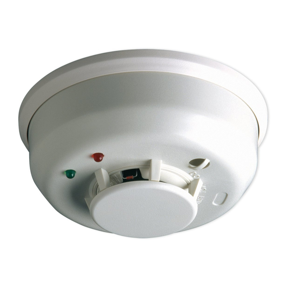
Two LEDs and a sounder on the detector provide local visual and
audible indication of the detector's status:
INSTALLATION AND SETUP GUIDE
5808W3 Photoelectronic Smoke/Temperature
Detector with Built-in Wireless Transmitter
Table 1: Detector LED Modes
Power-up
Normal (standby)
Out of sensitivity
Freeze Trouble
Smoke Alarm
Thermal Alarm
Low Battery
During initial power-up, the red and green LEDs will blink
synchronously once every 5 seconds. It will take approximately 20
seconds for the detector to finish the power-up cycle (see Table 1).
After power-up has completed and the detector is functioning
normally within its listed sensitivity range, the green LED blinks
once every 10 seconds. If the detector is in need of maintenance
because its sensitivity has shifted outside the listed limits, the red
LED blinks once every 5 seconds. When alarm has been activated
by smoke, the red LED blinks every 1 second. During a thermal
alarm condition (>135°F) the red LED blinks once every 4 seconds.
The LED indication must not be used in place of the tests specified
under Testing. In a freeze trouble condition, the red LED will blink
once every 10 seconds (refer to Table 1). If the detector senses a low
battery condition, the red LED blinks once every 45 seconds.
To measure the detector's sensitivity, the i3 Series Model SENS-
RDR Infrared Sensitivity Reader tool (see Figure 4) should be used.
Refer to instruction manual D100-98-00 for proper use of the SENS-
RDR.
Low Battery Detection
The 5808W3 is powered by a single 3-volt CR123A or DL123A
Lithium battery (included). The detector checks for a low battery at
least every 65 minutes. If a low battery is detected, the transmitter
sends a low battery message to the control panel, which beeps and
displays the detector's zone number. In addition, the red LED of the
5808W3 will blink every 45 seconds and the test switch will be
disabled. This condition will exist for a minimum of 7 days, and
then the detector's horn will "chirp" about every 45 seconds.
Pressing the test switch during this time will silence the chirps for
12 hours. The battery should be replaced BEFORE the chirps begin.
Be sure to replace the battery with a fresh one.
-1-
Green LED
Red LED
Piezoelectric
Horn
Blinks every
Blinks every
Off
5 sec
5 sec
Blinks every
Off
Off
10 sec
Off
Blinks every
Off
5 sec
Off
Off
Blinks every
10 sec
Off
Temporal Pattern
Blinks every
1 sec
Off
Blinks every
Temporal Pattern
4 sec
Off
Blinks every
Chirp every 45 sec
45 sec
after LED blinks for
7 days
Advertisement

Related Manuals for Honeywell Photoelectronic Smoke/Temperature Detector 5808W3


Summary of Contents for Honeywell Photoelectronic Smoke/Temperature Detector 5808W3
- Page 1 Proper Use of System Smoke Detectors, which provides detailed information on detector spacing, placement, zoning, wiring, and special applications. Copies of this manual are available from Honeywell. NOTICE: This manual should be left with the owner/user of this equipment. IMPORTANT: This detector must be tested and maintained regularly following NFPA 72 requirements.
- Page 2 Battery Installation and Replacement To replace the battery: Remove the detector from its mounting base by twisting the detector counterclockwise. Remove the battery, and dispose properly. To ensure proper power-down sequence, wait a minimum of 20 seconds before installing new battery. Install a new 3-volt CR123A Lithium battery in the battery compartment.
- Page 3 Dust covers are an effective way to limit the entry of dust into the smoke detector sensing chamber during construction. However, they may not completely prevent airborne dust particles from entering the detector. Therefore, it is recommended that the detectors be removed before beginning construction or other dust producing activity.
- Page 4 32° to 100°F (0° to 38°C) 0% to 95% Relative Humidity 135° F Fixed Temperature Electronic Thermistors 41°F (5°C) UL 268 – Commercial and Residential Installations 165 Eileen Way, Syosset, New York 11791 Copyright © 2005 Honeywell International Inc. www.honeywell.com/security REMOVABLE DETECTOR COVER SCREEN/SENSING...
Need help?
Do you have a question about the Photoelectronic Smoke/Temperature Detector 5808W3 and is the answer not in the manual?
Questions and answers
I replaced the battery but alarm is still chirping
The Honeywell Photoelectronic Smoke/Temperature Detector 5808W3 may still chirp after replacing the battery if it has been in a maintenance-required condition for at least 7 days. In this case, the detector’s horn will chirp about every 45 seconds. Pressing the test switch will silence the chirps for 12 hours, but the battery should be replaced before the chirps begin. Ensure that the replacement battery is fresh and correctly installed.
This answer is automatically generated