Table of Contents

Related Manuals for Honeywell Mark III


Summary of Contents for Honeywell Mark III
- Page 1 Technical Overview For Mark III Communications Management Unit (CMU) 23 July 2002 HONEYWELL Aerospace Electronic Systems Page 1 Use or disclosure of information on this page is subject to the restrictions on the title page of this document.
- Page 2 HONEYWELL Aerospace Electronic Systems Page 2 Use or disclosure of information on this page is subject to the restrictions on the title page of this document.
- Page 3 Mark III offers the capability to grow for tomorrow's rapidly expanding datalink requirements. The Mark III CMU is the next generation in CMU products. It offers over 100 Mbytes of memory (64 MB of volatile memory and 48 MB of non-volatile memory). Utilizing a Pentium 266 MHz processor and 2 Power PC dedicated I/O processors, the Mark III also offers a significant increase in processing power over other CMUs in the industry.
- Page 4 Once a user generates a new AMI, implementation is as simple as generating a disk containing the new AMI database and using the Mark III CMU dataload capability to load the AMI into each aircraft with no certification effort required.
- Page 5 The Mark III CMU offers a datalink user the next generation ARINC 758 CMU capable of providing the datalink functionality to meet the industry demands for today and tomorrow.
- Page 6 Providing world-wide Weather messages to the aircraft, as well as being an FAA approved distributor of messages such as Pre-Departure Clearances and ATIS. The Honeywell Aircraft Maintenance and Operational Support System (AMOSS) provides ground ACARS message processing and integration with flight planning systems.
-
Page 7: System Overview
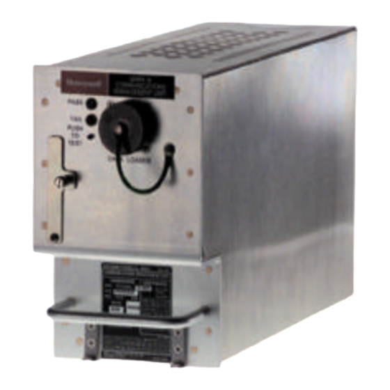
Mark III CMU. The Mark III CMU is a single Line Replaceable Unit (LRU) housed in a standard 4 MCU ARINC 600 form factor. The Mark III CMU contains 4 Circuit Card Assemblies (CCAs): (1) Processor; (2) I/O; (3) Power Supply;... -
Page 8: Table Of Contents
ARINC 607 defines the Aircraft Personality Module (APM) which contains all aircraft and system configuration information. The APM is external to the MARK III CMU and is a permanent fixture in the aircraft. Only one APM is required per MARK III CMU installation (one APM for each MARK III CMU mounting tray). -
Page 9: Vhf Radio
The Mark III CMU supports an interface with one ARINC 716 VHF radio. The interface supports VDL Mode 0, via an audio line to the Minimum Shift Keying (MSK) modem resident in the Mark III. There is also a low speed ARINC 429 transmit interface between the CMU and the ARINC 716 radio that is used to send frequency tuning information. -
Page 10: Satellite Data Unit (Sdu)
ARINC 429 receivers in place to support such future need, if ever required. It should be noted that the Mark III CMU baseline does include the interface to the Mode S in order to obtain the ICAO 24 character address (which is then used for verification of data in the APM). -
Page 11: Printer
Figure 2.2.2-1 Datalink Display Units Printer The Mark III CMU can interface with a single ARINC 740 or 744 compliant printer via low speed ARINC 429. This includes Honeywell’s ARINC 740 printer, as well as all other manufacturer’s who support the ARINC 740/744 specification. - Page 12 2.2.3 LRU Interfaces In general, the Mark III CMU can support any LRU that uses the ARINC 429 File Data Transfer Protocol or Williamsburg Protocol to communicate as an end system, as defined in ARINC 619 (ACARS file transfer protocols for other devices). ARINC 758 identifies a number of specific LRUs and the Mark III CMU supports...
-
Page 13: Gpssu
Electronic Library System (ELS) Although there are no ELS systems in use today which interface to CMUs, the Mark III CMU can be configured in the future to interface with a single ELS operating as an end system via high speed ARINC 429. -
Page 14: Airborne Data Loader
PCMCIA is Honeywell’s recommended method of performing complete full software loads. OOOI The Mark III CMU provides up to 6 high speed ARINC 429 inputs and a number of analog discrete inputs that can be used to determine Out/Off/On/In events. Data available on these interfaces typically include oil pressure, weight on wheels (WOW), flaps, parking brake, and doors. - Page 15 A prime example is the Embraer regional jet family. The Honeywell standalone Mark III CMU has been selected by many airlines for their ERJ-135 and ERJ-145 aircraft. The next generation ERJ-170 and ERJ-190 contain the Primus Epic integrated avionics cockpit which includes the CMF.
- Page 16 Mark II CMU and competitors CMUs, which still maintain much of this processing within an AOC software segment. With the Mark III CMU, all such functionality is contained within the AMI, providing airlines significantly more control and flexibility for performing changes, as requirements change.
- Page 17 Honeywell received the 1 FAA certification in December 2001. This initial certification was for Embraer aircraft. The Mark III CMU has since also been type certified by Boeing. Contact Honeywell for up-to-date information on other certifications completed or in work.
-
Page 18: Functional Overview
Functionality sections are configurable via the AMI or the HGI. The Mark III CMU supports an ARINC 739 MCDU, an ARINC 739 MIDU, and a CDU for displaying ACARS information. For the purpose of simplifying the text of this section, 'datalink display' will be used generically to mean MCDU, MIDU, or CDU. - Page 19 Although there is a default routing table, the user can modify the table via the AMI. The flight crew will be notified of uplink display messages destined for the Mark III CMU by a visual and potentially an aural alert, depending upon the alert level specified in the uplink message decoding definition.
- Page 20 (See Figure 8 for an example). The baseline subnetworks include VHF (mode 0/A), SATCOM, and HFDL. Figure 8 World Regions HONEYWELL Aerospace Electronic Systems Page 20 Use or disclosure of information on this page is subject to the restrictions on the title page of this document.
- Page 21 Some of the system pages support maintenance operations such as viewing/programming the APM, viewing and downloading fault data, and viewing the Mark III CMU part numbers. These pages are not part of the AMI, but rather part of the basic Mark III CMU system.
- Page 22 DMT as a product the airline operator needs). Data Loading The baseline Mark III CMU supports ARINC 615 data loading via the front connector for portable dataloading, through the rear connector for ADL processing or via PCMCIA memory cards through the front of the unit.
- Page 23 GMSK STDMA The baseline Mark III CMU supports Mode 0 (an analog line to the MSK modem) and Mode A (a W429 link to the radio which has an embedded MSK modem. Mode 2 utilizes a different modulation scheme (D8PSK) allowing a throughput increase from 2.4 kbps to 31.5 kbps.
- Page 24 The Mark III CMU was specifically developed to support the addition of this new ATN software, without any hardware modifications to the unit. This will be a future upgrade option for the Mark III CMU.
- Page 25 As part of this work, Honeywell is currently under contract with the U.S. government to define long term concepts for encryption and authentication associated with use in ATN and non-ATN environments. HONEYWELL Aerospace Electronic Systems Page 25 Use or disclosure of information on this page is subject to the restrictions on the title page of this document.
- Page 26 There are three primary databases contained with the Mark III CMU. The AMI database defines the airlines AOC functions. This is the database that either Honeywell or the Airline can create, and update at any time, using a PC based tool (GBST). The second database is the HGI database. The HGI is a database similar to the AMI, but contains information that is considered by certification authorities as requiring certification control.
- Page 27 The Ground Based Software Tool is the single windows-based PC tool that is used to generate AMIs (by the customer) and HGIs (by Honeywell). The FIDB is an input to the GBST and the output is a diskette containing a HGI or AMI that can be data loaded into the Mark III CMU (see Figure 11).
- Page 28 The following sections provides some additional information on how the GBST is used for reconfiguring the Mark III CMU, with the intent of identifying some of the major features of the GBST.
- Page 29 Display Editor. With the GBST, each of the AOC screens can be designed / customized to meet the individual needs of each airline. Figure 12 Main Menu HONEYWELL Aerospace Electronic Systems Page 29 Use or disclosure of information on this page is subject to the restrictions on the title page of this document.
- Page 30 Figure 13 shows page 2 of the example Main Menu. Figure 13 Main Menu Page 2 HONEYWELL Aerospace Electronic Systems Page 30 Use or disclosure of information on this page is subject to the restrictions on the title page of this document.
- Page 31 The GBST supports the screen layouts for both the standard ARINC 739 14 line MCDU/MIDU as well as supporting Honeywell’s 9 line CDU (used on various aircraft types such as the Embraer 135/145, and others). Figure 14 shows an example Main Menu on a 9 line CDU.
- Page 32 This discussion of the GBST and how it is used is equally applicable to both the AMI and the HGI. However, the HGI is only modifiable by Honeywell as it contains controlled data that requires re-certification upon change. There is a baseline HGI for both the 14 line MCDU/MIDU and the 9 line CDU. Therefore, the set of ATS menus and screens will be pre-defined and the user will only need to ensure that there is an ATS prompt on one of the menus (typically the Main Menu) that invokes the ATS menu.
- Page 33 These pages are part of the Mark III embedded operational software (not part of the reconfigurable AOC screens). When defining the AMI, the user would also tie in the System pages from one of the menu prompts. Figure 16 depicts an example System Menu.
- Page 34 Figure 17 Clearance Uplink HONEYWELL Aerospace Electronic Systems Page 34 Use or disclosure of information on this page is subject to the restrictions on the title page of this document.
- Page 35 Figure 18 Clearance Message Elements HONEYWELL Aerospace Electronic Systems Page 35 Use or disclosure of information on this page is subject to the restrictions on the title page of this document.
- Page 36 In this case, the footer is common to both the Clearance Uplink screen and the Reject Reasons page. HONEYWELL Aerospace Electronic Systems Page 36 Use or disclosure of information on this page is subject to the restrictions on the title page of this document.
- Page 37 The user can also specify a REJECT REASONS action prompt, which allows the flight crew to specify the reason for rejecting the Clearance (see Figure 20). Figure 20 Reject Reasons HONEYWELL Aerospace Electronic Systems Page 37 Use or disclosure of information on this page is subject to the restrictions on the title page of this document.
- Page 38 The optional entry box is only displayed for entry when the value of the reject reason is "other". Figure 21 Reject Reasons Values HONEYWELL Aerospace Electronic Systems Page 38 Use or disclosure of information on this page is subject to the restrictions on the title page of this document.
- Page 39 Within the properties of the downlink message display, the user can specify the review category the message will be placed into. HONEYWELL Aerospace Electronic Systems Page 39 Use or disclosure of information on this page is subject to the restrictions on the title page of this document.
- Page 40 (Figure 25). The message properties allows the user to define the downlink buffer and allowable subnetworks. HONEYWELL Aerospace Electronic Systems Page 40 Use or disclosure of information on this page is subject to the restrictions on the title page of this document.
- Page 41 Figure 24 Divert Message Elements Figure 25 Divert Properties HONEYWELL Aerospace Electronic Systems Page 41 Use or disclosure of information on this page is subject to the restrictions on the title page of this document.
- Page 42 Figure 26 shows the print format for a Flight Initialization uplink. This allows the user to define formats for uplink messages, as well as Mark III CMU generated reports to be easily readable by the flight crew. It also allows the flexibility to modify such formats as user requirements change.
- Page 43 Figure 27 OOOI Logic Unit 4.2.6 Preferred Channel Management Honeywell first introduced the concept to the industry of automated frequency management based on aircraft position. This is in contrast to the brute force approach of performing frequency management by trial and error based on a table of possible frequencies.
- Page 44 Using the map in Figure 29, the example USA region is comprised of three areas (Figure 30). Area 1 defines the continental US, area 2 defines Alaska, and area 3 Hawaii. HONEYWELL Aerospace Electronic Systems Page 44...
- Page 45 Figure 29 US Map HONEYWELL Aerospace Electronic Systems Page 45 Use or disclosure of information on this page is subject to the restrictions on the title page of this document.
- Page 46 B-777 GBST will find that only minimal training is required due to the common human interface used between the two tools. The GBST for the Mark III CMU is also designed to operate on a PC, using either Windows NT or Windows 2000 (Windows 2000 recommended).
-
Page 47: Hardware Description
5 HARDWARE DESCRIPTION 5.1 Mechanical Design The MARK III is a modular design that consists of a number of circuit card assemblies (CCAs) which are enclosed in a lightweight aluminum chassis. The internal interconnect between circuit card assemblies consists of a combination of highly reliable card-to-card connections and aerospace quality ribbon cables. - Page 48 5.1.2 Processor CCA The processor circuit card assembly contains the MARK III core microprocessor, supporting logic circuits, and memory devices. Significant features of the A2 CCA are as follows: Pentium Microprocessor Timers Heartbeat monitor contained in Field Programmable Gate Array (FPGA)
- Page 49 5.1.5 Spare CCAs (Growth) The MARK III provides two CCA growth slots for expansion. The growth slots may be used to provide an integrated VHF Data Radio (VDR) into the MARK III, memory expansion to allow the CMU to act as an aircraft file server, or other product variants.
- Page 50 Digital Data 429 BC: 1,2,3,4,5,6,7,8,9 (For 6 OOOI 429 Inputs, 1 GPS, and 2 FMC Figure 32 Mark III Supported ARINC 429 Interfaces HONEYWELL Aerospace Electronic Systems Use or disclosure of information on this page is subject to the restrictions on the title page of this document.
-
Page 51: Audio
716 Mode) PCMCIA Size II Card Figure 33 Mark III Supported Non-ARINC 429 Interfaces HONEYWELL Aerospace Electronic Systems Use or disclosure of information on this page is subject to the restrictions on the title page of this document. Ethernet Interface... - Page 52 5.3.1 Unit Weight The MARK III LRU maximum weight is twelve pounds. 5.3.2 Unit Size The MARK III LRU is a 4-MCU box that meets the dimensional specifications in ARINC 600. The unit has the following dimensions in inches: Width* MARK III 4.88 + .020...
-
Page 53: Environmental Specifications
In-Flight Loss of Cooling (DO-160D Section 4.5.4) Category W, 90 minutes minimum The MARK III shall be able to operate with no forced cooling air at an ambient of +40 Celsius for a period of 90 minutes. Temperature Variation (DO-160D Section 5.0) Category B, Non-controlled temperature, Equipment mounted internal in aircraft The maximum temperature variation rate is 5 Celsius per minute. - Page 54 Lightning Indirect Effects (DO-160D Section 22.0) Category A2E2, Equipment and interconnect wiring installed in a moderately exposed environment HONEYWELL Aerospace Electronic Systems Page 54 Use or disclosure of information on this page is subject to the restrictions on the title page of this document.
-
Page 55: Power Requirements
5.5 Power Requirements The MARK III is able to accept either 115 Vac 400 Hertz and/or 28 Vdc input power. The unit is designed so that if both sources are inadvertently connected, the MARK III or aircraft will not be damaged. - Page 56 Maximum 5.5.3 28 Vdc Backup Input Power Requirements The MARK III does not require use of standby 28 Vdc Battery Backup Input Power. 5.5.4 Power Interrupt Requirements The MARK III shall be capable of continuous operation through any power-off transient under 200 milliseconds.
- Page 57 The Mark III CMU hardware has also been designed to not only meet the required interfaces as identified in the new ARINC 758 characteristic, but contains additional interfaces to support potential future growth options.
- Page 58 In addition, due to the size of the memory on the Mark III CMU, the Mark II CMU is capable of a single database across all of the aircraft in an airline’s fleet of aircraft. This will allow an airline to have not only the same software but also the same database (thus identical and single configuration) across the complete fleet.
- Page 59 The Mark III CMU is designed to provide airlines with a hardware platform with the best growth potential of any system in the market. Not only does it contain significantly more processing power than other systems; it is also designed to support such future capabilities as Gatelink. The software within the Mark III CMU is also designed to provide customers with more control over AOC functional changes.
Need help?
Do you have a question about the Mark III and is the answer not in the manual?
Questions and answers