Table of Contents
Advertisement
BEFORE SERVICING ......................................................................................................INSIDE FRONT COVER
WARNING TO SERVICE PERSONNEL ................................................................................................................ 1
MICROWAVE MEASUREMENT PROCEDURE ................................................................................................... 2
FOREWORD AND WARNING ............................................................................................................................... 3
PRODUCT SPECIFICATIONS .............................................................................................................................. 4
GENERAL INFORMATION ................................................................................................................................... 4
OPERATION .......................................................................................................................................................... 6
TROUBLESHOOTING GUIDE .............................................................................................................................. 9
TEST PROCEDURE ............................................................................................................................................ 10
TOUCH CONTROL PANEL ................................................................................................................................. 18
COMPONENT REPLACEMENT AND ADJUSTMENT PROCEDURE ................................................................ 22
PICTORIAL DIAGRAM ........................................................................................................................................ 28
POWER UNIT CIRCUIT ...................................................................................................................................... 29
CPU UNIT CIRCUIT ............................................................................................................................................ 30
PRINTED WIRING BOARD ................................................................................................................................. 31
PARTS LIST ........................................................................................................................................................ 32
PACKING AND ACCESSORIES ......................................................................................................................... 36
SHARP CORPORATION
SERVICE MANUAL
MODELS
ON
DEF. LBS.
QTY. CHECK
To adjust quantity-t ouch
pad again
POP COR N
BEV ERA GE
DINN ER
REH EAT
PLAT E
CASS ERO LE
BAK ED
FRE SH
POT ATO
VEG ETAB LE
FRE SH
FRO ZEN
ROLL / MUFF IN
ROLL / MUFF IN
1
Grou nd meat
2
Steak s / chop
COM PU
s
3
Chic ken piece
DEF ROS T
s
In the interest of user-safety the oven should be restored to its original
POW ER
TIME R
LEVE L
CLOC K
STO P
STAR T
CLEA R
MINU TE PLUS
condition and only parts identical to those specified should be used.
WARNING TO SERVICE PERSONNEL: Microwave ovens con-
tain circuitry capable of producing very high voltage and
current, contact with following parts may result in a severe,
possibly fatal, electrical shock. (High Voltage Capacitor, High
Voltage Power Transformer, Magnetron, High Voltage Recti-
fier Assembly, High Voltage Harness etc..)
TABLE OF CONTENTS
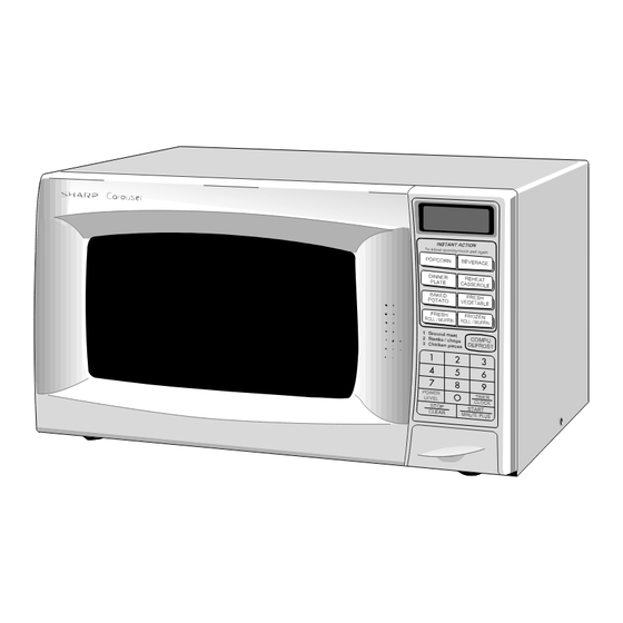
MICROWAVE OVEN
R-310BK
R-310BW
This document has been published to be used for after
sales service only.
The contents are subject to change without notice.
R-310BK
R-310BW
S4809R310BPW/
Page
Advertisement
Table of Contents

Related Manuals for Sharp R-310BK


Summary of Contents for Sharp R-310BK
-
Page 1: Table Of Contents
R-310BK R-310BW SERVICE MANUAL S4809R310BPW/ MICROWAVE OVEN R-310BK MODELS DEF. LBS. QTY. CHECK R-310BW To adjust quantity-t ouch pad again POP COR N BEV ERA GE DINN ER REH EAT PLAT E CASS ERO LE BAK ED FRE SH POT ATO... -
Page 2: Precautions To Be Observed Before And During Servicing To Avoid Possible Exposure To Excessive Microwave Energy
Before servicing an operative unit, perform a microwave emission check as per the Microwave Measurement Procedure outlined in this service manual. If microwave emissions level is in excess of the specified limit, contact SHARP ELECTRONICS CORPORATION immediately @1-800-237-4277. If the unit operates with the door open, service person should 1) tell the user not to operate the oven and 2) contact SHARP ELECTRONICS CORPORATION and Food and Drug Administration's Center for Devices and Radiological Health immediately. -
Page 3: Warning To Service Personnel
R-310BK R-310BW WARNING TO SERVICE PERSONNEL Microwave ovens contain circuitry capable of pro- ducing very high voltage and current, contact with following parts may result in a severe, possibly fatal, electrical shock. (Example) High Voltage Capacitor, High Voltage Power Trans- former, Magnetron, High Voltage Rectifier Assem- bly, High Voltage Harness etc.. -
Page 4: Microwave Measurement Procedure
R-310BK R-310BW MICROWAVE MEASUREMENT PROCEDURE A. Requirements: 1) Microwave leakage limit (Power density limit): The power density of microwave radiation emitted by a microwave oven should not exceed 1mW/cm at any point 5cm or more from the external surface of the oven, measured prior to acquisition... -
Page 5: Foreword And Warning
MICROWAVE OVEN R-310BK/ R-310BW GENERAL INFORMATION FOREWORD This Manual has been prepared to provide Sharp Electronics Corp. OPERATION Service Personnel with Operation and Service Information for the SHARP MICROWAVE OVEN, R-310BK, R-310BW. It is recommended that service personnel carefully study the entire... -
Page 6: Product Specifications
R-310BK R-310BW SPECIFICATION ITEM DESCRIPTION Power Requirements 120 Volts / 14 Amperes 60 Hertz Single phase, 3 wire grounded Power Output 1100 watts (IEC-705 TEST PROCEDURE) Operating frequency of 2450MHz Case Dimensions Width 20-1/2" Height 11-7/8" Depth 15-7/8" Cooking Cavity Dimensions Width 13-3/4"... -
Page 7: Oven Diagram
R-310BK R-310BW A short power-supply cord is provided to reduce risks of becoming entangled in or tripping over a longer cord. Grounded 3-Pronged Plug Receptacle Box Where a two-pronged wall-receptacle is encountered, it is the personal responsibility and obligation of the customer to contact a qualified... -
Page 8: Operation
R-310BK R-310BW OPERATION DESCRIPTION OF OPERATING SEQUENCE The following is a description of component functions during so that it will function in the following sequence. oven operation. (1) When the door opens from the closed position, the primary interlock relay (RY2) and secondary interlock OFF CONDITION switch open their contacts. - Page 9 R-310BK R-310BW SCHEMATIC NOTE: CONDITION OF OVEN 1. DOOR CLOSED 2. CLOCK APPEARS ON DISPLAY THERMAL MONITOR THERMAL CUT-OUT (OVEN) FUSE 20A CUT-OUT (MG.) COM. POWER N.O. TRANSFORMER (RY-2) (RY-1) PRIMARY INTERLOCK RELAY CONTROL UNIT N.O. COM. SH-B SH-A 120V AC...
- Page 10 R-310BK R-310BW DESCRIPTION AND FUNCTION OF COMPONENTS DOOR OPEN MECHANISM open, the monitor fuse blows simultaneously with closing of the monitor switch contacts. The door is opened by pushing the open button on the CAUTION: BEFORE REPLACING A BLOWN MONITOR control panel, refer to the Figure D-1.
-
Page 11: Troubleshooting Guide
R-310BK R-310BW TROUBLESHOOTING GUIDE Never touch any part in the circuit with your hand or an uninsulated tool while the power supply is connected. When troubleshooting the microwave oven, it is helpful to follow the Sequence of Operation in performing the checks. Many of the possible causes of trouble will require that a specific test be performed. -
Page 12: Test Procedure
R-310BK R-310BW CK = Check / RE = Replace RE RE A B C D E F F G H RE RE CK I CKCK CK J K L M TEST PROCEDURE PROBLEM CONDITION Home fuse or circuit breaker blows when power cord is plugged... - Page 13 R-310BK R-310BW TEST PROCEDURES PROCEDURE COMPONENT TEST LETTER MAGNETRON ASSEMBLY TEST 1. Disconnect the power supply cord, and then remove outer case. 2. Open the door and block it open. 3. Discharge high voltage capacitor. 4. To test for an open filament, isolate the magnetron from the high voltage circuit. A continuity check across the magnetron filament leads should indicate less than 1 ohm.
- Page 14 R-310BK R-310BW TEST PROCEDURES PROCEDURE COMPONENT TEST LETTER (HIGH VOLTAGES ARE PRESENT AT THE HIGH VOLTAGE TERMINAL, SO DO NOT ATTEMPT TO MEASURE THE FILAMENT AND HIGH VOLTAGE.) HIGH VOLTAGE RECTIFIER TEST 1. Disconnect the power supply cord, and then remove outer case.
- Page 15 R-310BK R-310BW TEST PROCEDURES PROCEDURE COMPONENT TEST LETTER 5. Reconnect all leads removed from components during testing. 6. Reinstall the outer case (cabinet). 7. Reconnect the power supply cord after the outer case is installed. 8. Run the oven and check all functions.
- Page 16 R-310BK R-310BW TEST PROCEDURES PROCEDURE COMPONENT TEST LETTER with the door opened (in this condition the plunger of the monitor switch is pushed in), the meter should indicate an open circuit. If improper operation is indicated, the switch may be defective. After testing the monitor switch, reconnect the wire lead to the monitor switch (COM) terminal and check the continuity of the monitor circuit.
- Page 17 R-310BK R-310BW TEST PROCEDURES PROCEDURE COMPONENT TEST LETTER 7) Reconnect the power supply cord after the outer case is installed. 8) Run the oven and check all functions. The following symptoms indicate a defective key unit. a) When touching the pads, a certain pad produces no signal at all.
- Page 18 R-310BK R-310BW TEST PROCEDURES PROCEDURE COMPONENT TEST LETTER the above method may be used (after clearing the control unit) to determine if the control unit or key pad is at fault. 5. Reconnect all leads removed from components during testing.
- Page 19 R-310BK R-310BW TEST PROCEDURES PROCEDURE COMPONENT TEST LETTER (5) If improper operation is indicated, the control unit is probably defective and should be checked. FOIL PATTERN ON THE PRINTED WIRING BOARD TEST To protect the electronic circuits, this model is provided with a fine foil pattern added to the primary on the PWB, this foil pattern acts as a fuse.
-
Page 20: Touch Control Panel
R-310BK R-310BW TOUCH CONTROL PANEL ASSEMBLY OUTLINE OF TOUCH CONTROL PANEL The touch control section consists of the following units. 3) Power Source Circuit This circuit generates voltages necessary in the control (1) Key Unit unit from the AC line voltage. - Page 21 R-310BK R-310BW DESCRIPTION OF LSI LSI(IZA891DR) The I/O signals of the LSI(IZA891DR) are detailed in the following table. Signal Description Segment data signal. SEG0-SEG11 Connected to LCD. The relation between signals are as follows: LSI signal LCD (Pin No.) LSI signal LCD (Pin No.)
- Page 22 R-310BK R-310BW Pin No. Signal I/O Description Key strobe signal. Signal applied to touch-key section. A pulse signal is input to R60 - R63 terminal while one of G7 line keys on key matrix is touched. Key strobe signal. Signal applied to touch-key section. A pulse signal is input to R60 - R63 terminal while one of G6 line keys on key matrix is touched.
- Page 23 R-310BK R-310BW TOUCH CONTROL PANEL SERVICING 5) Re-connect the power supply cord after the outer case 1. Precautions for Handling Electronic Components is installed. This unit uses CMOS LSI in the integral part of the circuits. 6) Run the oven and check all functions.
-
Page 24: Component Replacement And Adjustment Procedure
4. If the outer case (cabinet) is not fitted. WARNING FOR WIRING To prevent an electric shock, take the following pre- 3) Sharp edge: cautions. Bottom plate, Oven cavity, Waveguide flange, 1. Before wiring, Chassis support and other metallic plate. -
Page 25: Pictorial Diagram
R-310BK R-310BW CAUTION: 1. DISCONNECT OVEN FROM POWER SUP PLY BEFORE REMOVING OUTER CASE. 2. DISCHARGE THE HIGH VOLTAGE CA- PACITOR BEFORE TOUCHING ANY OVEN COMPONENTS OR WIRING. Special screw NOTE: When replacing the outer case, the 2 special Torx screws must be reinstalled in the same locations. - Page 26 R-310BK R-310BW MAGNETRON REMOVAL Removal cavity front plate and the back plate. 1. Disconnect the power supply cord and remove outer case. 4. Re-install the chassis support to magnetron with the one 2. Open the door and block it open.
- Page 27 7. Now the turntable motor is free. 4. Where the corners have been snipped off bend corner areas flat. No sharp edges must be evident after removal 8. After replacement use the one (1) screw to fit the turntable motor cover.
- Page 28 R-310BK R-310BW 7. Install the fan duct assembly to the oven cavity with the 9. Install the magnetron and the chassis support to the one (1) screw. oven cavity, referring to "Re-install of MAGNETRON 8. Insert the snap of the main wire harness to the hole of the REMOVAL".
-
Page 29: Door Replacement
5. Hold the door panel to the door frame with the two (2) or Sealer film Backing film three (3) screws (2 for R-310BW and 3 for R-310BK) . 6. Put sealer film on door panel. Refer to "Sealer Film" about how to handle new one. - Page 30 R-310BK R-310BW RECTIFIER H.V.
-
Page 31: Power Unit Circuit
R-310BK R-310BW LD1 LD2 LD3 LD4 LD5 LD1-LD5 WH-1 R4 27 Q2 2SB1238 D1-D4 11ES1 R5 4.7k – – 820 1/2w 820 1/2w N.O. TURNTABLE R6 3.3k MOTOR OVEN LAMP MOTOR N.O. MICRO Q3 DTD143ES SH-B DOOR SWITCH 10 /35v –... -
Page 32: Cpu Unit Circuit
R-310BK R-310BW 33p/50v COM1 INT2 COM2 COM3 COM4 PULSE SEG0 SEG1 AIN3 SEG2 AIN2 SEG3 AIN1 SEG4 AIN0 330p/50v 330p/50v 330p/50v 330p/50v 220k 220k 220k 220k (J14) 4.7k (J15) (J12) 4.7k (J13) 4.7k (J11) (J10) /50v /25v 0.01 UD4.3B ZD10... -
Page 33: Printed Wiring Board
R-310BK R-310BW WH - 1 (CN - C) CN - C CN - B CN - A (CN - D) (D10) Figure S-4. Printed Wiring Board of Power Unit... -
Page 34: Parts List
3- 2 DPWBFB796WRK0 CPU unit 3- 3 FPNLCB277WRK0 Control panel frame with key unit [R-310BW] 3- 3 FPNLCB281WRK0 Control panel frame with key unit [R-310BK] 3- 3- 1 FUNTKA792WRE0 Key unit [R-310BW] 3- 3- 1 FUNTKA795WRE0 Key unit [R-310BK] 3- 4... - Page 35 To have your order filled promptly and correctly, please furnish the following information. 1. MODEL NUMBER 3. PART NO. 2. REF. NO. 4. DESCRIPTION Order Parts from the authorized SHARP parts Distributor for your area. Defective parts required return should be returned as indicated in the Service Policy.
-
Page 36: Oven And Cabinet Parts
R-310BK R-310BW OVEN AND CABINET PARTS 1-11 1-10 1-13 4-17 4-16 4-10 4-21 4-15 4-12 4-14 1-12 4-20 4-11 4-19 1-14 4-13... - Page 37 R-310BK R-310BW CONTROL PANEL PARTS 3-1F 3-3-1 DOOR PARTS 4-18 5-10 for R-310BK only 5-9 for R-310BK only for R-310BK only MISCELLANEOUS (HIGH VOLTAGE TRANSFORMER) (CAPACITOR) Actual wire harness may be different from illustration.
-
Page 38: Packing And Accessories
R-310BK R-310BW PACKING AND ACCESSORIES TOP PAD ASSEMBLY FPADBA341WRK0 DOOR PROTECTION SHEET CABINET COVER for R-310BK SPADPA204WRE0 SPAKHA003WRE0 PLASTIC BAG SSAKHA034WRE0 6- 8 INSTRUCTION BOOK & PRINTING MATTER 6- 2 TURNTABLE TRAY BOTTOM PAD ASSEMBLY FPADBA342WRK0 6- 1 TURNTABLE SUPPORT... - Page 39 R-310BK R-310BW...
- Page 40 No part of this publication may be repro- duced, stored in a retrieval systems, or trans- mitted in any form or by any means, elec- tronic, mechanical, photocopying, record- ing, or otherwise, without prior written per- mission of the publisher. '98 SHARP CORP. (4S2.530E) Printed in U.S.A...
Need help?
Do you have a question about the R-310BK and is the answer not in the manual?
Questions and answers