Table of Contents
Advertisement
The T8611M Chronotherm III Programmable
Thermostat provides automatic control of multi-
stage heat pump systems and offers users the
highest standard of comfort and convenience
available with energy savings.
Full seven-day program capability; different sched-
ules may be selected for every day.
Can be programmed in hand (with batteries in-
stalled) or on the wall to provide up to four tem-
perature periods per day.
Large digital clock (liquid crystal display) indi-
cates continuous time-of-day, day-of-week, cur-
rent period and room temperature.
Adaptive Intelligent Recovery™ brings room tem-
perature to programmed temperature at program-
med time, maximizing comfort and energy sav-
ings.
Temperature control program maintains tempera-
ture within 1 F of setpoint.
Temporary program override available by using-
-WARMER and COOLER keys.
-SKIP next period key.
-CHANGE to last period key.
HOLD TEMP key provided for indefinite program
override (vacation/holiday).
Installer self-test with time delay override saves
installation time.
SYSTEM light-emitting diode (LED) on thermo-
temperature sensing.
(7-Day Programming)
Chronotherm III™
Heat Pump Thermostats
1
C. H. • Rev. 10-92 • ©Honeywell Inc. 1992 • Form Number 68-0076-1
T8611M
stat indicates system is energized.
AUX. HT., EM. HT., CHECK LEDs available on
select models.
Automatic heat/cool changeover.
Batteries included provide power to maintain clock
and memory during power failures.
Switching subbase with wiring terminals included.
Powered directly from control transformer.
Model available with separate sensor for remote
CONTENTS
Specifications ................................................. 2
Ordering Information ..................................... 2
Selection/Application ..................................... 5
Installation ................................................... 12
Checkout ....................................................... 18
Programming The Thermostat ..................... 20
Operating The Thermostat ........................... 25
Operation ..................................................... 27
Troubleshooting ........................................... 29
Glossary ....................................................... 30
Table of Contents ......................................... 32
68-0076-1
Advertisement
Chapters
Table of Contents

Related Manuals for Honeywell CHRONOTHERM III T8611M


Summary of Contents for Honeywell CHRONOTHERM III T8611M
-
Page 1: Table Of Contents
Checkout ... 18 Programming The Thermostat ... 20 Operating The Thermostat ... 25 Operation ... 27 Troubleshooting ... 29 Glossary ... 30 Table of Contents ... 32 C. H. • Rev. 10-92 • ©Honeywell Inc. 1992 • Form Number 68-0076—1 T8611M 68-0076—1... -
Page 2: Specifications
If you have additional questions, need further information or would like to comment on our products or services, please write or phone: 1. Your local Honeywell Home and Building Control Sales Office (check white pages of your phone directory). 2. Home and Building Control Customer Satisfaction Honeywell inc., 1885 Douglas Drive North... - Page 3 Fig. 1—T8611 Subbase mounting dimensions in in. [mm]. [46] [135] M5181A Fig. 2—202905AA Remote Sensor dimensions in in. [mm]. FRONT [104] [83] [121] 7 [179] SIDE [50] [50] 64 [16] [35] T8611M SPECIFICATIONS [50] [104] BACK [51] DIA. [13] 1 [25] M5244 68-0076—1...
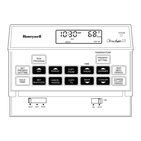
- Page 4 T8611M SPECIFICATIONS Fig. 3—Typical thermostat keypad. PROGRAM PRESENT DAY/TIME HOLD TEMP HEAT/COOL HEAT MIDDAY COPY PERIOD FROM CANCEL COPY PERIOD COOL SYSTEM ROOM HEAT ON TEMPERATURE PRESENT SETTING TIME SKIP NEXT AHEAD WARMER PERIOD CHANGE BACK COOLER TO LAST PERIOD AUTO M5360...
-
Page 5: Selection/Application
Can a new cable be pulled? Selection 4 heat and • existing thermostat 4 cool — Table 3 is a guide for replacing popular Honeywell standard nonprogrammable thermostats with a T8611. 4 heat and SECURITY 4 cool... - Page 6 Remote Temperature Sensing TABLE 2—T8611M FEATURES AND TERMINALS. COMMENTS May be applied to 2-stage heat pump systems; see wiring diagrams Figs. 6 and 7. Auto 7-day Lights on call for heat or cool. Lights continuously in EM. HEAT mode.
- Page 7 TABLE 3—T8611 GUIDE FOR REPLACING POPULAR T874 AND T872 THERMOSTATS, (NOTE: Also see form 70-6627, Heat Pump Thermostat Cross Reference Guide, for wiring hookup illustrations.) Thermostat (Subbase Included) Auto Manual Changeover Changeover Weekday, Weekday, Sat, Sun Sat, Sun Auto T8611G1004...
- Page 8 T8611M SELECTION/APPLICATION TABLE 3—T8611 GUIDE FOR REPLACING POPULAR T874 AND T872 THERMOSTATS, BY EQUIPMENT MANUFACTURER (Continued). (NOTE: Also see form 70-6627, Heat Pump Thermostat Cross Reference Guide, for wiring hookup illustrations.) Thermostat (Subbase Included) Auto Manual Changeover Changeover Weekday, Weekday,...
- Page 9 TABLE 3—T8611 GUIDE FOR REPLACING POPULAR T874 AND T872 THERMOSTATS, BY EQUIPMENT MANUFACTURER (Continued). (NOTE: Also see form 70-6627, Heat Pump Thermostat Cross Reference Guide, for wiring hookup illustrations.) Thermostat (Subbase Included) Auto Manual Changeover Changeover Weekday, Weekday, Sat, Sun...
- Page 10 T8611M SELECTION/APPLICATION TABLE 3—T8611 GUIDE FOR REPLACING POPULAR T874 AND T872 THERMOSTATS, BY EQUIPMENT MANUFACTURER (Continued). (NOTE: Also see form 70-6627, Heat Pump Thermostat Cross Reference Guide, for wiring hookup illustrations.) Thermostat (Subbase Included) Auto Manual Changeover Changeover Weekday, Weekday,...
- Page 11 TABLE 3—T8611 GUIDE FOR REPLACING POPULAR T874 AND T872 THERMOSTATS, BY EQUIPMENT MANUFACTURER (Continued). (NOTE: Also see form 70-6627, Heat Pump Thermostat Cross Reference Guide, for wiring hookup illustrations.) Thermostat (Subbase Included) Auto Manual Changeover Changeover Weekday, Weekday, Sat, Sun...
-
Page 12: Installation
— unheated (uncooled) areas behind the sensor, such as an outside wall. IF REPLACING AN EXISTING THERMOSTAT Turn thermostat power off at furnace or heat pump. Installation This thermostat requires a single transformer. A two- transformer system may require turning off two switches or disconnects, and rewiring to run the thermostat from a single transformer. -
Page 13: Mounting Remote Temperature Sensor
Fig. 4—Removing thermostat from subbase. The subbase mounts directly onto the wall with the screws and anchors included. Instead, the subbase can be mounted on a vertical or horizontal outlet box. If you must mount the subbase on a vertical outlet box, order 193121A Adapter Assembly. - Page 14 SWITCH TO R (POWER) SIDE OF SYSTEM TRANSFORMER SOME OLDER HEAT PUMP THERMOSTATS USE X FOR COMMON TERMINAL. NOMINAL 24 Vac POWER MUST BE PRESENT BETWEEN R AND C TERMINALS FOR THERMOSTAT OPERATION. RECOMMENDED INTERCONNECT CABLE: 18-GAUGE THERMOSTAT CABLE, 200 ft. [61 m] MAXIMUM LENGTH. ROUTE INTERCONNECT CABLE AWAY FROM SOURCES OF ELECTRICAL NOISE.
- Page 15 SYSTEM TRANSFORMER OF SYSTEM TRANSFORMER SOME OLDER HEAT PUMP THERMOSTATS USE X FOR COMMON TERMINAL. NOMINAL 24 Vac POWER MUST BE PRESENT BETWEEN R AND C TERMINALS FOR THERMOSTAT OPERATION. RECOMMENDED INTERCONNECT CABLE: 18-GAUGE THERMOSTAT CABLE, 200 ft. [61 m] MAXIMUM LENGTH. ROUTE INTERCONNECT CABLE AWAY FROM SOURCES OF ELECTRICAL NOISE.
- Page 16 SWITCH TO R (POWER) SIDE OF SYSTEM TRANSFORMER SOME OLDER HEAT PUMP THERMOSTATS USE X FOR COMMON TERMINAL. NOMINAL 24 Vac POWER MUST BE PRESENT BETWEEN R AND C TERMINALS FOR THERMOSTAT OPERATION. RECOMMENDED INTERCONNECT CABLE: 18-GAUGE THERMOSTAT CABLE, 200 ft. [61 m] MAXIMUM LENGTH. ROUTE INTERCONNECT CABLE AWAY FROM SOURCES OF ELECTRICAL NOISE.
-
Page 17: Adjusting Cycle Rate
A CHANGE IN CYCLE RATE. The room air temperature normally will vary slightly from the comfort temperature setting with the cycling of the heat pump or auxiliary heater. Fig. 11—Cycle rate adjustment. Fig. 12—Battery placement. The Stage 1 cycle rate of this thermostat is factory-set for heat pumps and cannot be adjusted. -
Page 18: Checkout
Fig. 13—Mounting thermostat on subbase. CAUTION During cold weather, some heat pumps will re- quire that crankcase heater be energized several hours before operating heat pump. Refer to manufacturer’s recommendations. HEATING NOTE: When heating setting is changed, thermostat will wait up to 5 minutes before turning on the heating equipment. -
Page 19: Fan
Move the system switch to OFF, and the fan switch to ON. The fan should run continuously. When the fan switch is in the AUTO position, fan cycles with the heating or cooling system. INSTALLER SELF-TEST (OPTIONAL) IMPORTANT: • Thermostat must have ac power to perform self-test. •... -
Page 20: Programming The Thermostat
T8611M CHECKOUT • PROGRAMMING THE THERMOSTAT First Digit Degrees Second Digit System Switch Position EM. HT., HEAT or OFF STEP 1 SETTING THE CURRENT DAY AND TIME This thermostat can be programmed either on the wall or in the hand. See page 12 to remove the thermostat from the subbase. - Page 21 Program the MIDDAY time and heat- ing temperature if desired. NOTE: It is possible to cancel any period showing on the display ex- cept MORNING by pushing the CANCEL PERIOD key. To move to the next period while program- ming, simply press the PERIOD key again.
- Page 22 T8611M PROGRAMMING THE THERMOSTAT Program the NIGHT time and tem- perature, if desired. Set the cooling temperatures for all the periods programmed. The program times are the same for both heating and cooling. Only the cooling temperatures need to be programmed if program- ming has been completed for heating.
-
Page 23: Copying The Program To The Desired Days
STEP 3 COPYING THE PROGRAM TO THE DESIRED DAYS It is possible to copy the program for one day to any other day or combina- tion of days. The new program will replace any program already set in the day selected. STEP 4 SETTING THE SCHEDULES AND TEMPERATURES FOR... -
Page 24: Setting The System And Fan Switches On The Subbase
EM. HT., the fan operates with the auxiliary heat (on some models). EM. HT: The thermostat controls only the backup heat. The heat pump is off. HEAT: The thermostat controls the heat- ing system. OFF: Both the heating and cooling sys- tems are off. -
Page 25: Operating The Thermostat
Then set the system switch. (contin- ued) Now, read on to learn about the oper- ating flexibility that makes this ther- mostat THE SMART CHOICE. TEMPORARILY CHANGING THE PROGRAM These features allow customizing the program for those times when some- one comes home early, is working late or planning to be out for the evening. -
Page 26: Reprogramming The Thermostat
T8611M OPERATING THE THERMOSTAT REPROGRAMMING THE THERMOSTAT If schedule changes or a different tem- perature is desired, update any setting without affecting the rest of the pro- gram. Copy the new program into other days, if desired. When copying a program, all the times and temperatures for that day HOLDING A TEMPERATURE FOR EXTENDED ABSENCE... -
Page 27: Operation
The first heat stage is the heat pump and the last stage is electric, gas, or oil auxiliary heat. T8611M provides automatic changeover from heat to cool or cool to heat. -
Page 28: What To Expect During Recovery From Energy Savings Heating
During the comfort period, the heat pump will cycle on and off as needed to maintain the sensed temperature within +/-1 F of the setpoint. -
Page 29: Troubleshooting
CHECK POWER TO HEAT PUMP OR AUXILIARY HEATING SYSTEM –ON-OFF SWITCH –FUSE OR CIRCUIT BREAKER –LOOSE 24 V CONNECTION -AT THERMOSTAT -AT HEAT PUMP OR AUXILIARY HEATING SYSTEM –INCORRECT WIRING -CHECK WIRING DIAGRAM CONDUCT SELF-TEST; SEE CHECKOUT. ADJUST TEMPERATURE BY PUSHING WARMER/COOLER KEYS. -
Page 30: Glossary
This light glows whenever the thermostat is calling for operation of the backup heater. Backup (auxiliary) heat is more expensive to operate than the heat pump, and typi- cally is used only when the heat pump is unable to handle the load (located on subbase). CHECK light (yellow) Consult heat pump literature to determine its meaning (located on subbase). -
Page 31: Table Of Contents
Specifications ... 2 Ordering Information ... 2 Selection/Application ... 5 Installation ... 12 Compatibility ... 12 Location ... 12 Mounting Subbase ... 12 Mounting Remote Temperature Sensor ... 13 Wiring ... 13 Adjusting Cycle Rate ... 17 Installing Batteries ... 17 Power Outages ... - Page 32 Home and Building Control Home and Building Control Honeywell Inc. Honeywell Limited—Honeywell Limitée 1985 Douglas Drive North 740 Ellesmere Road Golden Valley, MN 55422 Scarborough, Ontario M1P 2V9 Printed in U.S.A. Helping You Control Your World QUALITY IS...