Table of Contents
Advertisement
Quick Links
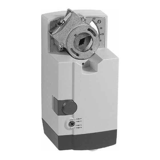
N20, N34 Series MN7220, MN7234
NON-SPRING RETURN DAMPER ACTUATOR
20/34 Nm (175/300 lb-in) FOR MODULATING CONTROL
GENERAL
These direct-coupled damper actuators provide modulating
control for:
• rotary valves,
• air handling units,
• ventilation flaps,
• louvers, and
• reliable control for air damper applications with up to 50
sq.ft. (20 Nm / 175 lb-in) or 85 sq. ft. (34 Nm / 300 lb-in)
(seal-less damper blades; air friction-dependent).
FEATURES
• New self-centering shaft adapter
• Access cover to facilitate connectivity
• Declutch for manual adjustment
• Mechanical end limits (MN7220 only)
• Field-installable auxiliary switches
• Rotation direction selectable by switch
• Mountable in any orientation (no IP54 if upside down)
• Mechanical position indicator
SPECIFICATIONS
Supply voltage
Nominal voltage
All values stated hereinafter apply to operation under
nominal voltage conditions.
Power consumption
MN7220
MN7234
Ambient limits
Ambient operating limits
Ambient storage limits
Relative humidity
Safety
Protection standard
Protection class
Overvoltage category
Lifetime
Full strokes
Repositions
Mounting
Round damper shaft
Square damper shaft
Shaft length
Control signal
Input impedance
Feedback signal
Limits
Auxiliary switch (when included)
Rating
Triggering points
Torque rating
MN7220
MN7234
Runtime
Rotation stroke
Dimensions
Weight
Noise rating
PRODUCT DATA
24 Vac ±20%, 50/60 Hz;
24 Vdc -10...+20%
24 Vac, 50/60 Hz; 24 Vdc
6 VA / 6 W
8 VA / 6 W
-5...+140 °F (-20...+60 °C)
-40...+175 °F (-40...+80 °C)
5...95%, non-condensing
IP54 (non-USA models)
NEMA2 (USA models)
II as per EN 60730-1
II
60000
1.5 million
3/8...1-1/16" (10...27 mm)
3/8...11/16" (10...18 mm);
45° steps
min. 7/8" (22 mm)
0(2)...10 Vdc
0(4)...20 mA
100 kΩ [0...10 V]
500 Ωm [0...20 mA]
± 1 mA at 0...10 V
5 A (resistive) / 3 A (inductive)
5° / 85°
175 lb-in (20 Nm)
300 lb-in (34 Nm)
95 sec (60 Hz) / 110 sec (50 Hz)
95° ± 3°
see "Dimensions" on page 8
3 lbs. (1.35 kg)
40 dB(A) max. at 1 m
63-2587-1
Advertisement
Table of Contents

Related Manuals for Honeywell MN7220


Summary of Contents for Honeywell MN7220
-
Page 1: Specifications
• New self-centering shaft adapter • Access cover to facilitate connectivity • Declutch for manual adjustment • Mechanical end limits (MN7220 only) • Field-installable auxiliary switches • Rotation direction selectable by switch • Mountable in any orientation (no IP54 if upside down) •... -
Page 2: Operation Functions
If you have additional questions, need further information, or would like to comment on our products or services, please write or phone: 1. Your local Honeywell Automation and Control Products Sales Office (check white pages of your phone directory). 2. Honeywell Customer Care... -
Page 3: Rotary Movement
Table 1. Feedback/control signal values1. The stroke has now been limited to 0...100% of the control signal range. N20, N34 SERIES MN7220, MN7234 voltage/current control signal dip switch ( autoadapt dip switch for normal operation ( 63-2587—1... -
Page 4: Installation
N20, N34 SERIES MN7220, MN7234 Voltage/Current Control Signal Selection Dip Switch In its default shipping position, the voltage/current control signal dip switch (see Fig. 4) is set to OFF (= voltage control). as shown in Fig. 4. Setting it to ON results in current control. -
Page 5: Mounting Position
Depending upon the model, the access cover may have one or two terminal strips, including a layout with a description for each of the terminals. Fig. 12. Actuator with access cover removed N20, N34 SERIES MN7220, MN7234 Fig. 11. Access cover 63-2587—1... -
Page 6: Terminal Strip
N20, N34 SERIES MN7220, MN7234 Wiring Diagrams MN7220/MN7234 24 Vac 24 Vdc 0(2)...10 Vdc 0(4)...20 mA 0(2)...10 Vdc TERMINAL STRIP 1 MODULATING CONTROL MN7220 WITH SWITCHES 24 Vac 24 Vdc TERMINAL STRIP 0(2)...10 Vdc 0(4)...20 mA 0(2)...10 Vdc MODULATING AUXILIARY NOTE: Internal auxiliary switches S1 and S4 must be connected to the same power source. - Page 7 N20, N34 SERIES MN7220, MN7234 63-2587—1...
- Page 8 N20, N34 SERIES MN7220, MN7234 DIMENSIONS 100 mm (3-15/16”) shaft adapter adapter (reverse) min. 60 mm (2-3/8”) 20 mm (25/32”) 2 mm (5/64”) Automation and Control Solutions Honeywell International Inc. Honeywell Limited-Honeywell Limitée 1985 Douglas Drive North 35 Dynamic Drive...
Need help?
Do you have a question about the MN7220 and is the answer not in the manual?
Questions and answers