Table of Contents
Advertisement
BEFORE SERVICING ...................................................................................................... INSIDE FRONT COVER
WARNING TO SERVICE PERSONNEL ................................................................................................................ 1
MICROWAVE MEASUREMENT PROCEDURE ................................................................................................... 2
FOREWORD AND WARNING ............................................................................................................................... 3
PRODUCT SPECIFICATIONS .............................................................................................................................. 4
GENERAL INFORMATION ................................................................................................................................... 4
OPERATION .......................................................................................................................................................... 6
TROUBLESHOOTING GUIDE .............................................................................................................................. 9
TEST PROCEDURE ............................................................................................................................................ 10
TOUCH CONTROL PANEL ................................................................................................................................. 18
COMPONENT REPLACEMENT AND ADJUSTMENT PROCEDURE ................................................................ 22
PICTORIAL DIAGRAM ........................................................................................................................................ 28
POWER UNIT CIRCUIT ...................................................................................................................................... 29
CPU UNIT CIRCUIT ............................................................................................................................................ 30
PRINTED WIRING BOARD ................................................................................................................................. 31
PARTS LIST ........................................................................................................................................................ 32
PACKING AND ACCESSORIES ......................................................................................................................... 36
SHARP CORPORATION
SERVICE MANUAL
MODELS
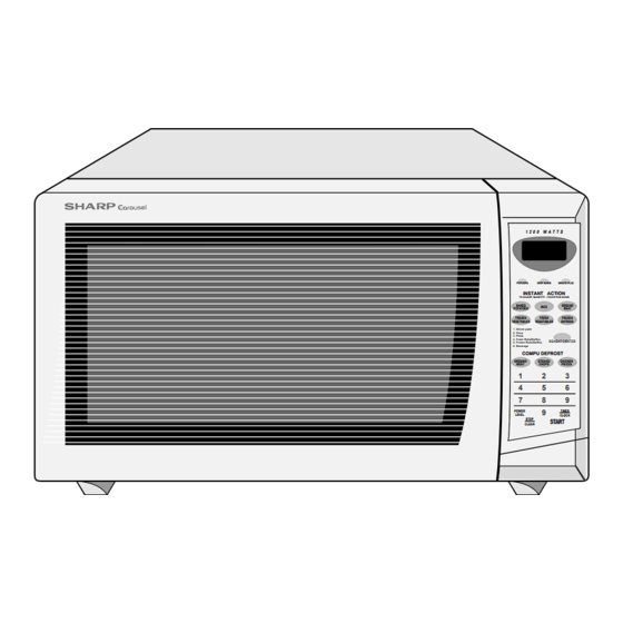
1 2 0 0 W A T T S
POPCORN
KEEP WARM
MINUTE PLUS
INSTANT ACTION
TO ADJUST QUANTITY - TOUCH PAD AGAIN
BAKED
RICE
GROUND
POTATOES
MEAT
FROZEN
FRESH
FROZEN
VEGETABLES
VEGETABLES
ENTREES
1. Dinner plate
2. Soup
3. Pizza
4. Fresh Rolls/Muffins
5. Frozen Rolls/Muffins
REHEAT CENTER
6. Beverage
COMPU DEFROST
STEAKS/
CHICKEN
GROUND
MEAT
CHOPS
PIECES
1
2
3
4
5
6
7
8
9
In the interest of user-safety the oven should be restored to its original
POWER
9
TIMER
LEVEL
CLOCK
STOP
START
CLEAR
condition and only parts identical to those specified should be used.
WARNING TO SERVICE PERSONNEL: Microwave ovens con-
tain circuitry capable of producing very high voltage and
current, contact with following parts may result in a severe,
possibly fatal, electrical shock. (High Voltage Capacitor, High
Voltage Power Transformer, Magnetron, High Voltage Recti-
fier Assembly, High Voltage Harness etc..)
TABLE OF CONTENTS
This document has been published to be used for after
sales service only.
The contents are subject to change without notice.
39
MICROWAVE OVEN
R-510EK
R-510EW
R-510EK
R-510EW
S2105R510EUW/
Page
Advertisement
Table of Contents

Related Manuals for Sharp R-510EK


Summary of Contents for Sharp R-510EK
-
Page 1: Table Of Contents
R-510EK R-510EW SERVICE MANUAL S2105R510EUW/ MICROWAVE OVEN R-510EK MODELS 1 2 0 0 W A T T S R-510EW POPCORN KEEP WARM MINUTE PLUS INSTANT ACTION TO ADJUST QUANTITY - TOUCH PAD AGAIN BAKED RICE GROUND POTATOES MEAT FROZEN FRESH... -
Page 2: Precautions To Be Observed Before And During Servicing To Avoid Possible Exposure To Excessive Microwave Energy
Before servicing an operative unit, perform a microwave emission check as per the Microwave Measurement Procedure outlined in this service manual. If microwave emissions level is in excess of the specified limit, contact SHARP ELECTRONICS CORPORATION immediately @1-800-237-4277. If the unit operates with the door open, service person should 1) tell the user not to operate the oven and 2) contact SHARP ELECTRONICS CORPORATION and Food and Drug Administration's Center for Devices and Radiological Health immediately. -
Page 3: Warning To Service Personnel
R-510EK R-510EW WARNING TO SERVICE PERSONNEL Microwave ovens contain circuitry capable of pro- ducing very high voltage and current, contact with following parts may result in a severe, possibly fatal, electrical shock. (Example) High Voltage Capacitor, High Voltage Power Trans- former, Magnetron, High Voltage Rectifier Assem- bly, High Voltage Harness etc.. -
Page 4: Microwave Measurement Procedure
R - 5 10 E K R- 510EW MICROWAVE MEASUREMENT PROCEDURE A. Requirements: 1) Microwave leakage limit (Power density limit): The power density of microwave radiation emitted by a microwave oven should not exceed 1mW/cm at any point 5cm or more from the external surface of the oven, measured prior to acquisition by a purchaser, and thereafter (through the useful life of the oven), 5 mW/cm at any point 5cm or more from the external surface of the oven. -
Page 5: Foreword And Warning
MICROWAVE OVEN R-510EK/ R-510EW GENERAL INFORMATION FOREWORD This Manual has been prepared to provide Sharp Electronics Corp. Service Personnel with Operation and Service Information for the SHARP MICROWAVE OVEN, R-510EK, R-510EW. OPERATION It is recommended that service personnel carefully study the entire text of this manual so that they will be qualified to render satisfactory customer service. -
Page 6: Product Specifications
R - 5 10 E K R- 510EW SPECIFICATION ITEM DESCRIPTION Power Requirements 120 Volts / 13.8 Amperes/ 1650 Watts 60 Hertz Single phase, 3 wire grounded Power Output 1200 watts (IEC TEST PROCEDURE) Operating frequency of 2450MHz Case Dimensions Width 24"... -
Page 7: Oven Diagram
R-510EK R-510EW contact a qualified electrician and have it replaced with a properly Grounded grounded three-pronged wall receptacle or have a grounding adapter Receptacle Box properly grounded and polarized. If the extension cord must be used, it should be a 3-wire, 15 amp. or higher rated cord. Do not drape over a... -
Page 8: Operation
R - 5 10 E K R- 510EW OPERATION DESCRIPTION OF OPERATING SEQUENCE The following is a description of component functions during relay and is mechanically associated with the door so oven operation. that it will function in the following sequence. (1) When the door opens from the closed position, the OFF CONDITION primary interlock relay (RY2) and secondary interlock... -
Page 9: Oven Schematic-Off Condition
R-510EK R-510EW CHEMATIC NOTE: CONDITION OF OVEN 1. DOOR CLOSED. 2. CLOCK APPEARS ON DISPLAY. NOTE: Indicates components with potential above 250 V. MAGNETRON MONITOR TEMP. FUSE 20A FUSE COM. N.O. CAPACITOR 1.0 F AC 2300V (RY-2) (RY-1) PRIMARY INTERLOCK... -
Page 10: Description And Function Of Components
R - 5 10 E K R- 510EW DESCRIPTION AND FUNCTION OF COMPONENTS DOOR OPEN MECHANISM open, the monitor fuse blows simultaneously with closing of the monitor switch contacts. The door is opened by pushing the open button on the CAUTION: BEFORE REPLACING A BLOWN MONITOR control panel, refer to the Figure D-1. -
Page 11: Troubleshooting Guide
R-510EK R-510EW TROUBLESHOOTING GUIDE Never touch any part in the circuit with your hand or an uninsulated tool while the power supply is connected. When troubleshooting the microwave oven, it is helpful to follow the Sequence of Operation in performing the checks. Many of the possible causes of trouble will require that a specific test be performed. -
Page 12: Test Procedure
R - 5 10 E K R- 510EW CK = Check / RE = Replace RE RE A B C D E E F F G H RE RE CK I CK CK CK J K L M TEST PROCEDURE PROBLEM CONDITION Home fuse or circuit breaker blows... - Page 13 R-510EK R-510EW TEST PROCEDURES PROCEDURE COMPONENT TEST LETTER 4. To test for an open filament, isolate the magnetron from the high voltage circuit. A continuity check across the magnetron filament leads should indicate less than 1 ohm. 5. To test for a shorted magnetron, connect the ohmmeter leads between the magnetron filament leads and chassis ground.
- Page 14 R - 5 10 E K R- 510EW TEST PROCEDURES PROCEDURE COMPONENT TEST LETTER HIGH VOLTAGE RECTIFIER TEST 1. Disconnect the power supply cord, and then remove outer case. 2. Open the door and block it open. 3. Discharge high voltage capacitor. 4.
- Page 15 R-510EK R-510EW TEST PROCEDURES PROCEDURE COMPONENT TEST LETTER CAUTION: IF THE TEMPERATURE FUSE INDICATES AN OPEN CIRCUIT AT ROOM TEMPERA- TURE, REPLACE TEMPERATURE FUSE. SECONDARY INTERLOCK SWITCH TEST 1. Disconnect the power supply cord, and then remove outer case. 2. Open the door and block it open.
- Page 16 R - 5 10 E K R- 510EW TEST PROCEDURES PROCEDURE COMPONENT TEST LETTER 5. Reconnect all leads removed from components during testing. 6. Reinstall the outer case (cabinet). 7. Reconnect the power supply Screw Driver cord after the outer case is installed.
- Page 17 R-510EK R-510EW TEST PROCEDURES PROCEDURE COMPONENT TEST LETTER b) When touching a number pad, two figures or more are displayed. c) When touching the pads, sometimes a pad produces no signal. If the Key unit is defective. 1) Disconnect the power supply cord, and then remove outer case.
- Page 18 R - 5 10 E K R- 510EW TEST PROCEDURES PROCEDURE COMPONENT TEST LETTER 7. Reconnect the power supply cord after the outer case is installed. 8. Run the oven and check all functions. MINUTE CHICKEN PLUS PIECES FRESH STEAKS VEGETABLES CHOPS <COMPU...
- Page 19 R-510EK R-510EW TEST PROCEDURES PROCEDURE COMPONENT TEST LETTER FOIL PATTERN ON THE PRINTED WIRING BOARD TEST To protect the electronic circuits, this model is provided with a fine foil pattern added to the primary on the PWB, this foil pattern acts as a fuse.
-
Page 20: Touch Control Panel
R - 5 10 E K R- 510EW TOUCH CONTROL PANEL ASSEMBLY OUTLINE OF TOUCH CONTROL PANEL 3) Power Source Circuit The touch control section consists of the following units. This circuit generates voltages necessary in the control unit from the AC line voltage. (1) Key Unit In addition, the synchronizing signal is available in order (2) Control Unit (The Control Unit consists of Power Unit and... - Page 21 R-510EK R-510EW Pin No. Signal Description Back light circuit (Light emitting diodes) driving signal. 12-13 P56-P55 Terminal not used. CNTR0 Signal to sound buzzer (2.0 kHz). 0.1 sec. H : GND A: key touch sound. L : -5V B: Completion sound.
- Page 22 R - 5 10 E K R- 510EW Pin No. Signal Description Key strobe signal. Signal applied to touch-key section. A pulse signal is input to P41, P43, P44 and P45 terminal while one of G8 line keys on key matrix is touched. Key strobe signal.
- Page 23 R-510EK R-510EW TOUCH CONTROL PANEL SERVICING repair all the controls (sensor-related ones included) of 1. Precautions for Handling Electronic Components the touch control panel while keeping it connected to the This unit uses CMOS LSI in the integral part of the oven.
-
Page 24: Component Replacement And Adjustment Procedure
4. If the outer case (cabinet) is not fitted. WARNING FOR WIRING To prevent an electric shock, take the following pre- 3) Sharp edge: cautions. Bottom plate, Oven cavity, Waveguide flange, 1. Before wiring, Chassis support and other metallic plate. -
Page 25: Power Transformer Removal
R-510EK R-510EW CAUTION: 1. DISCONNECT OVEN FROM POWER SUP PLY BEFORE REMOVING OUTER CASE. 2. DISCHARGE THE HIGH VOLTAGE CA- PACITOR BEFORE TOUCHING ANY OVEN Special screw COMPONENTS OR WIRING. NOTE: When replacing the outer case, the 2 special Torx screws must be reinstalled in the same locations. - Page 26 4. Where the corners have been snipped off bend corner 7. Now the turntable motor is free. areas flat. No sharp edges must be evident after removal 8. After replacement use the one (1) screw to fit the of the turntable motor cover.
- Page 27 R-510EK R-510EW COOLING FAN MOTOR REMOVAL REMOVAL CAUTION: 1. Disconnect the power supply cord and then remove * Do not reuse the removed fan blade because the outer case. hole (for shaft) may be larger than normal. 2. Open the door and block it open.
- Page 28 R - 5 10 E K R- 510EW forth, and up and down. In and out play of the door 3. Monitor switch contacts close when door is opened. allowed by the upper and lower position of the latch hook 4.
- Page 29 R-510EK R-510EW chapter “Test Procedures”.). SEALER FILM (B) An approved microwave survey meter should be Installation used to assure compliance with proper microwave 1. Put the adhesive tape on the backing film of the sealer radiation emission limitation standards. film as shown in Fig. C-6.
-
Page 30: Pictorial Diagram
R - 5 10 E K R- 510EW... -
Page 31: Power Unit Circuit
R-510EK R-510EW CN-C S1NB10 9PIN LEAD WIRE HARNESS CN-A – OVEN LAMP TURNTABLE BUZZER MOTOR FAN MOTOR OVEN LAMP TURNTABLE MOTOR FAN MOTOR MICRO MICRO (BROWNER) DOOR SENSING SWITCH DOOR... -
Page 32: Cpu Unit Circuit
R - 5 10 E K R- 510EW COM1 COM2 COM3 SEG22 SEG21 SEG20 SEG19 SEG18 SEG17 SEG16 SEG15 SEG14 SEG13 SEG12 SEG11 SEG10 SEG7 SEG6 SEG5 SEG4 SEG3 SEG2 SEG1 SEG0 VREF XOUT AVSS COM3 COM2 COM1 RESET COM0 4.7k 4.7k 4.7k... -
Page 33: Printed Wiring Board
R-510EK R-510EW QKITPB034MRE0 CN-C CN-B MICRO OL TTM FM VRS1 CN-A FB034MR Figure S-4 . Printed Wiring Board of Power Unit... -
Page 34: Parts List
Power supply cord CABINET PARTS 2- 1 GDAI-B061MRP0 Base plate 2- 2 GLEGPB004MRF0 Foot 2- 3 GCABUB096MRP0 Outer case cabinet [R-510EK] 2- 3 GCABUB089MRP0 Outer case cabinet [R-510EW] CONTROL PANEL PARTS 3- 1 DPWBFB099MRU0 Power unit 3- 1A QCNCMA275DRE0 2-pin connector (CN-A) - Page 35 To have your order filled promptly and correctly, please furnish the following information. 1. MODEL NUMBER 2. REF. NO. 3. PART NO. 4. DESCRIPTION Order Parts from the authorized SHARP parts Distributor for your area. Defective parts requiring return should be returned as indicated in the Service Policy.
-
Page 36: Oven And Cabinet Parts
R - 5 10 E K R- 510EW OVEN AND CABINET PARTS 1-10 1-14 1-11 4-10 1-12 1-13 4-11 4-12... - Page 37 R-510EK R-510EW CONTROL PANEL PARTS DOOR PARTS MISCELLANEOUS Actual wire harness may be different from illustration.
-
Page 38: Packing And Accessories
R - 5 10 E K R- 510EW TOP PAD ASSEMBLY FPADBB050MRE0 PACKING AND ACCESSORIES DOOR PROTECTION SHEET SPADP0221MRE0 PLASTIC BAG SSAKHB007MRE0 TRAY HOLDER SPADFB051MRE0 6-5 TURNTABLE TRAY 6-8 OPERATION MANUAL 6-4 TURNTABLE SUPPORT BOTTOM PAD ASSEMBLY FPADBB051MRE0 TRAY PACK SPADPB042MRE0 PACKING CASE SPAKCB309MRE0... - Page 39 R-510EK R-510EW...
- Page 40 No part of this publication may be repro- duced, stored in retrieval systems, or trans- mitted in any form or by any means, elec- tronic, mechanical, photocopying, record- ing, or otherwise, without prior written per- mission of the publisher. 2001 SHARP CORP. (2S2.530E) Printed in U.S.A...
Need help?
Do you have a question about the R-510EK and is the answer not in the manual?
Questions and answers