Table of Contents
Advertisement
Quick Links
Manual
Sources
Input
L
Input 1
Return 1
On
Phase
Phase
Input 2
Return 2
Rev. L
Rev. R
Mono
Input 3
Return 3
L/R
Insert
Input 4
Return 4
On
Inputs
Returns
Pre Insert Trims
Trim L
Trim R
DMC
R
On
Dual-Channel Mastering Console
Monitor Level
%
Master Fader
dB
Model 2490
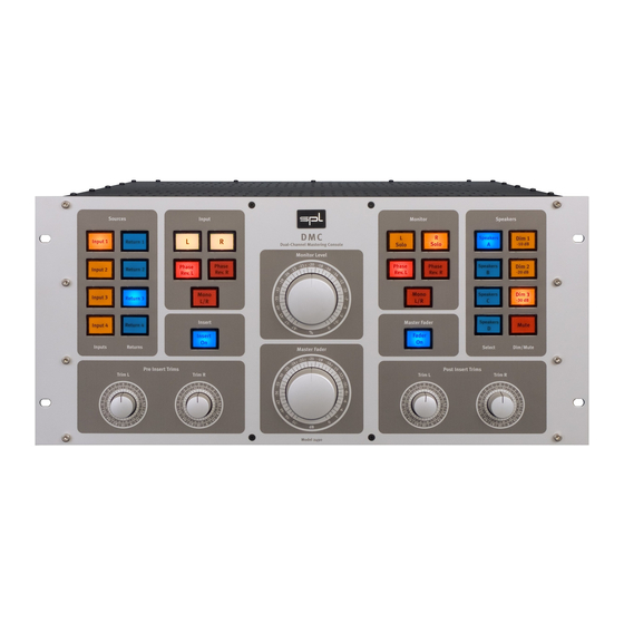
Dual-Channel Mastering Console DMC
Monitor
Speakers
Stereo
L
R
Dim
Solo
Solo
-10 dB
A
Stereo
Phase
Phase
Dim
Rev. L
Rev. R
B
-20 dB
Stereo
Mono
Dim
-30 dB
L/R
C
Master Fader
Stereo
Mute
D
On
Select
Dim/Mute
Post Insert Trims
Trim L
Trim R
Advertisement
Table of Contents

Subscribe to Our Youtube Channel
Summary of Contents for SPL 2490
- Page 1 Stereo Mono Input 3 Return 3 -30 dB Insert Master Fader Stereo Input 4 Return 4 Mute Inputs Returns Select Dim/Mute Master Fader Pre Insert Trims Post Insert Trims Trim L Trim R Trim L Trim R Model 2490 Manual...
- Page 2 However Sound Performance Lab (SPL) reserves the right to modify the product described in this manual at any time. Changes without notice. This document is the property of SPL and may not be copied or reproduced in any manner, in part or full without the authorization of SPL.
-
Page 3: Table Of Contents
Contents Fade In ..................... Option: MasterBay ................Signal Flow ..................Rear Panel ..................Control Surface ................Measurements ................Specifi cations ................. The Sections In Detail ..............Sources and Input ................Power Supply .................. Pre and Post Insert Trims, Insert, Monitor Section ...... - Page 4 They perform at an industry benchmark 120 volts and were developed during The purpose of the development was the creation of mastering consoles a four-year period during which SPL searched for a new generation of superior that would be superior in audio quality to all known and foreseeable audio discrete analog op amps.
-
Page 5: Signal Flow
Signal Flow INSERT SEND/RET. balanced drivers and receivers INSERT PHASE TRIM L TRIM L MASTER BALANCED STEREO STEREO REVERSE TRIM R TRIM R FADER INPUT MONO L/R RECORDING SWITCH INPUTS SWITCHES SWITCHES SWITCHES 0dB – infinity OUTPUTS RECEIVERS SWITCHES balanced passive +/- 10 dB relay... -
Page 6: Control Surface
Mono Stereo Mono Input 3 Return 3 -30 dB Stereo Insert Master Fader Input 4 Return 4 Mute Inputs Returns Select Dim/Mute Master Fader Pre Insert Trims Post Insert Trims Trim L Trim R Trim L Trim R Model 2490... -
Page 7: The Sections In Detail
The Sections In Detail Sources Sources The Sources section provides for the selection of four stereo inputs and four returns. The inputs are fed to the mastering path, the returns are fed to the monitoring section. Input 1 Return 1 Input 2 Return 2 The Source section is subdivided into two parts. - Page 8 The Sections In Detail Pre and Post Insert Trims Pre Insert Trims Post Insert Trims Trim L Trim R Trim L Trim R Sophisticated rotary trim switches with 32 steps are used for precise gaining from -10dB to +10dB for each Pre Insert L/R as well as Post Insert L/R channel. These switches route the signal through one precision resistor at any position only, keeping thermal noise and tolerance at an unrivalled minimum.
- Page 9 The Sections In Detail Master Fader Master Fader Master Fader This fader features the same level control potentiometer as in the Monitor Level section for dynamic mastering purposes and fi ne tuning the overall level from +10 dB to -80 dB. The range can also be customized to operate from 0 dB to -80 dB.
-
Page 10: Option: Masterbay
Option: Master Bay The DMC can optionally be complemented with an insert box called MasterBay. The MasterBay MasterBay consists of a 4U insert box and a remote control panel. Up to eight, 2-channel processors can be connected to the insert box, which is operated by the MasterBay remote panel. -
Page 11: Rear Panel
Rear Panel PUSH Pin Wiring XLR Outputs Pin Wiring XLR Inputs 1 = Ground, 2 = hot (+), 3 = cold (-) 1 = Ground, 2 = hot (+), 3 = cold (-) -
Page 12: Measurements
Measurements: CMRR Input, CMRR Return Audio Precision DMC A-A CMRR Input 10/26/04 11:24:25 Audio Precision DMC A-A CMRR Return 10/26/04 11:26:14 -100 -100 DMC CMRR Input.at2c DMC CMRR Return.at2c... - Page 13 Measurements: Frequency Responses Input/Speaker Out, Input/Insert Send Audio Precision DMC Frequenz Response Input - Speaker Out 10/26/04 09:38:30 Audio Precision DMC Frequenz Response Input - Insert Send 10/26/04 09:40:40 +4.5 +4.5 +3.5 +3.5 +2.5 +2.5 +1.5 +1.5 +0.5 +0.5 -0.5 -0.5 -1.5 -1.5...
- Page 14 Measurements: Frequency Responses Input/Rec. Out, Input/VU Meter Out Audio Precision DMC Frequency Response Input - RecOut 10/26/04 09:36:26 Audio Precision DMC Frequenz Response Input -VU Meter Out 10/26/04 09:42:45 +4.5 +4.5 +3.5 +3.5 +2.5 +2.5 +1.5 +1.5 +0.5 +0.5 -0.5 -0.5 -1.5 -1.5...
- Page 15 Measurements: Frequency Response Return/Speaker Out, THD&N Input/Rec. Out Audio Precision DMC Frequency Response Ret - Speaker Out 10/26/04 09:45:12 Audio Precision DMC THD+N vers AMPL Input - Rec Out 10/26/04 11:22:04 +4.5 +3.5 +2.5 +1.5 +0.5 -0.5 -100 -110 -1.5 -120 -2.5 The Analog Analyzer Function meter is in THD+N ratio mode.
- Page 16 Measurements: THD&N Input/Speaker Monitor Out, THD&N Input/VU Meter Out Audio Precision DMC THD+N vers AMPL Input - Speaker Monitor Out 10/26/04 09:27:13 Audio Precision DMC THD+N vers AMPL Input - VU Meter Out 10/26/04 09:28:33 -100 -100 -110 -110 -120 -120 The Analog Analyzer Function meter is in THD+N ratio mode.
- Page 17 Measurements: THD&N Input/Insert Send, Return/Speaker Monitor Out Audio Precision DMC THD+N vers AMPL Input - Insert Send 10/26/04 09:25:26 Audio Precision DMC THD+N vers AMPL Return - Speaker Monitor Out 10/26/04 09:46:37 -100 -100 -110 -110 -120 -120 The Analog Analyzer Function meter is in THD+N ratio mode. At low levels the noise floor accounts for the high percentage readings.
-
Page 18: Specifi Cations
Specifi cations Dynamic Range ›130 dB Max. input level ›30 dBu (Audio Precision generator limit +30 dBu) Noise (A-weighted) Recording Out: -102 dBu Monitor Out: -99,5 dBu Send: -103 dBu VU/Audio: -104 dBu Crosstalk Recording Out: -90 dBu Monitor Out: -75 dBu Send: -90 dBu... -
Page 19: Power Supply
Power Supply For optimal audio quality and dramatically reduced inductive disturbance/ interference, the DMC’s power supply is divided into two parts. The external part houses a toroidal transformer, the linear power supply is built into the DMC housing. Input voltage: 110-120 V/60 Hz or 220-240 V/50 Hz Noise: ›... -
Page 20: Warranty
SPL has been advised of this possibility, this limited warranty does not cover any such consequential or incidental damages. Some states or countries do not allow the limitations or exclusion of incidental or consequential damages, so the above limitation may not apply to you.
Need help?
Do you have a question about the 2490 and is the answer not in the manual?
Questions and answers