Table of Contents
Advertisement
Quick Links
Advertisement
Table of Contents

Related Manuals for Gear Lite ADC-9532

Summary of Contents for Gear Lite ADC-9532
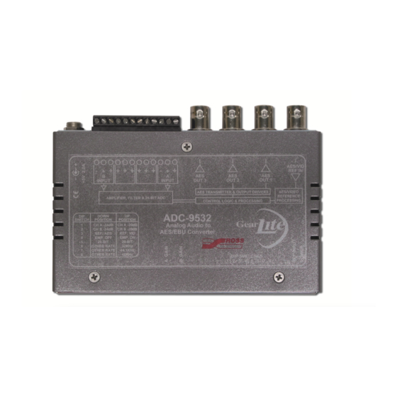
- Page 1 ADC-9532 Analog Audio to AES/EBU Converter User Manual...
- Page 2 Notice The material in this manual is furnished for informational use only. It is subject to change without notice and should not be construed as commitment by Ross Video Limited. Ross Video Limited assumes no responsibility or liability for errors or inaccuracies that may appear in this manual.
-
Page 3: Symbol Meanings
Important Regulatory and Safety Notices to Service Personnel Before using this product and any associated equipment, refer to the “Important Safety Instructions” listed below to avoid personnel injury and to prevent product damage. Product may require specific equipment, and/or installation procedures to be carried out to satisfy certain regulatory compliance requirements. -
Page 4: Important Safety Instructions
Important Safety Instructions Warning – Read these instructions. Keep these instructions. Heed all warnings. Follow all instructions. The safe operation of this product requires that a protective earth connection be provided. A grounding conductor in the equipment's supply cord provides this protective earth. To reduce the risk of electrical shock to the operator and service personnel, this ground conductor must be connected to an earthed ground. -
Page 5: Emc Notices
Notice — Changes or modifications to this equipment not expressly approved by Ross Video Limited could void the user’s authority to operate this equipment. CANADA This Class “A” digital apparatus complies with Canadian ICES-003. -
Page 6: Environmental Information
To avoid the potential release of those substances into the environment and to diminish the need for the extraction of natural resources, Ross Video encourages you to use the appropriate take-back systems. These systems will reuse or recycle most of the materials from your end-of-life equipment in an environmentally friendly and health conscious manner. - Page 7 Delta Sigma Modulator ADC. Three (3) copies of the unbalanced AES/EBU signal are provided on the BNC connectors on the rear of the unit. The ADC-9532 has the ability to phase and frequency lock to an external AES DARS reference (per AES11-1997) or to frequency lock to an external analog PAL or NTSC video reference.
-
Page 8: Simplified Block Diagram
ANLG REFERENCE SETTINGS VIDEO PROCESSING & STATUS REFERENCE Figure 1 Simplified Block Diagram of ADC-9532 Functions Features The ADC-9532 includes the following features: • Support for 32kHz, 44.1kHz, and 48kHz sampling rates • User selectable 20bit or 24bit ADC resolution •... -
Page 9: Static Discharge
If any items are missing or damaged, contact your sales representative or Ross Video directly. Mounting and Installation The ADC-9532 can be mounted in any convenient location. However, to ensure long life for this product, observe the following precautions and operating requirements: •... -
Page 10: Optional Mounting Accessories
Optional Mounting Accessories Ross Video is committed to providing practical solutions for the needs of your high-quality broadcast facility. 9 • Installation (Iss. 02) - Page 11 Step 1. Figure 3 Flat Metal Plate Installation Option Install the chassis in the desired location using the Mounting Holes on the Flat Metal Plate. Mounting screws are not provided by Ross Video. Angle Mounting Bracket The Angle Mounting Bracket (Figure 4) allows a single GearLite module to be installed in positions not possible with the flat metal plate.
- Page 12 Figure 4 Angle Mounting Bracket 11 • Installation (Iss. 02)
- Page 13 Refer to the section “Important Regulatory and Safety Notices to Service Personnel” at the front of this manual for details. Cable Connections Overview Connect the cables to the ADC-9532 according to the designations indicated on the chassis label and Figure 5. The ADC-9532 has the following cable connections: •...
-
Page 14: Analog Connections
Analog Connections On the rear edge of the ADC-9532 there is a removable 12-pin audio terminal block which has slots for the positive, negative, and grounded wires of two balanced analog audio cables. - Page 15 Set this switch UP to report the emphasis mode in the AES Channels status bits. The ADC-9532 does not add emphasis in the conversion process. This control is only used to indicate that the analog signal into the unit has emphasis.
-
Page 16: Status Leds
Set this switch UP to select the 44.1kHz sampling rate. Use with an AES reference only. Ensure SW6 and SW8 are DOWN. The ADC-9532 will only provide a 44.1kHz sampled signal as long as it has a valid 44.1kHz AES reference signal. On loss of the 44.1kHz AES reference signal, the ADC-9532 will switch to internal reference at an undefined sampling rate. -
Page 17: Potentiometer Setup
Green POWER When unlit, this LED indicates a loss of power. a.The ADC-9532 will track the AES reference signal if the rate selection is incorrect. Potentiometer Setup The ADC-9532 can accommodate any full-scale digital (FSD) level in the -17dBFS to -27dBFS range. The analog stereo input signal from the 12-pin terminal block consists of an A and B channel (left and right). - Page 18 Audio Levels 0dBFS Saturation Saturation Headroom Operating Level Operating Level +4dBu or +8dBu -20dBu or -24dBu DISTORTION DISTORTION Figure 9 Analog Audio Figure 10 Digital Audio Figure 9 illustrates amplitude vs. distortion for analog and digital audio equipment show that digital audio does not gradually degrade (become more distorted) as the amplitude increases.
-
Page 19: Technical Specifications
Specifications Technical Specifications Specifications are subject to change without notification. Table 5 ADC-9532 — Technical Specifications Category Parameter Specification 2 balanced channels (1 stereo Number of Inputs pair) via removable terminal strip Connector 12-pin screw-type Analog Audio Input Impedance >25kohm CMRR >70dB (20Hz to 20kHz) - Page 20 Table 5 ADC-9532 — Technical Specifications Category Parameter Specification Output Isolation 45dB AES/EBU Output Return Loss >45dB (0.1 to 6MHz) Output DC Offset <50mV Quantization 20bit or 24bit ±0.10dB @ 48kHz (20Hz to Frequency Response 20kHz) Measured at -20dBFS -102dB unweighted Signal to Noise Ratio -105dB ‘A’...
-
Page 21: Channel Status Data Table
Channel Status Data Table indicates fixed and configurable channel status bit information. Table 6 Channel Status Data Byte Function Transmitted Professional or Consumer Professional (1) use of Channel Status Block Normal Audio or Non-audio Normal Audio (0) mode • Not indicated or No emphasis (000) Emphasis: user selectable •... -
Page 22: Service Information
Service Information Warranty and Repair Policy The GearLite ADC-9532 is warranted to be free of any defect with respect to performance, quality, reliability, and workmanship for a period of THREE (3) years from the date of delivery to the customer. In the event that your GearLite... - Page 23 Notes: Service Information (Iss. 02) • 22...
-
Page 24: Technical Support
Contact Us Contact our friendly and professional support representatives for the following: • Name and address of your local dealer • Product information and pricing • Technical support • Upcoming trade show information Telephone: +1 613 • 652 • 4886 Technical After Hours Emergency: +1 613 •...
Need help?
Do you have a question about the ADC-9532 and is the answer not in the manual?
Questions and answers