Advertisement
SUPPLEMENTARY INFORMATION FOR THE DELTA
MODEL 36-790 RT-40 - 14" TILTING ARBOR SAW
IMPORTANT - The information in this document contains assembly and related instruction for your fence system. These
instructions replace the information on pages 7 and 8 in your table saw instruction manual (Part #422-28-651-0001) Keep
these supplemental instructions for future reference.
1.
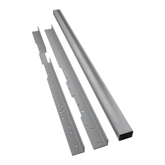
Front Rail
2.
Guide Tube
3.
Fence Assembly
4.
1/2"-13 x 2" Flat Head Bolts
5.
5/16" Hex Wrench
6.
1/2" Flat Washer
7.
1/2"-13 Hex Nuts
8.
Lockwasher
9.
Retaining Nut
10.
Retaining Nut Hex Bolt
11.
Retaining Nut Bolt
4
6
8
10
BIESEMEYER
12" - 14" Table Saw Fence System 52-1/2" Capacity
CARTON CONTENTS
5
7
9
11
(Model 78-920 T-Square
®
1
1346214_RevB_11-10-07
)
®
3
2
Advertisement
Table of Contents

Related Manuals for Biesemeyer 78-920 T-Square®

Summary of Contents for Biesemeyer 78-920 T-Square®
-
Page 1: Carton Contents
1346214_RevB_11-10-07 SUPPLEMENTARY INFORMATION FOR THE DELTA MODEL 36-790 RT-40 - 14" TILTING ARBOR SAW BIESEMEYER (Model 78-920 T-Square ® ® 12" - 14" Table Saw Fence System 52-1/2" Capacity IMPORTANT - The information in this document contains assembly and related instruction for your fence system. These instructions replace the information on pages 7 and 8 in your table saw instruction manual (Part #422-28-651-0001) Keep these supplemental instructions for future reference. - Page 2 ASSEMBLY Disconnect the machine from the power source. 1. Use three (3) 1/2-13 X 2" flat-head bolts, flat washers, lockwashers, and hex nuts (A) Fig. 1 to attach the guide rail to the front of the saw table (Fig. 2). Loosely tighten with the supplied hex wrench for further adjustment. Fig.
- Page 3 HOW TO OPERATE AND ADJUST THE RIP FENCE 1. To move the fence along the guide rail, lift the clamp lever (Fig. 7). 2. To lock the fence in position, push down on the clamp lever (Fig. 8). NOTE: The clamp lever will remain in the "up" position when you move the fence. Fig.
- Page 4 2. Apply grease to the cam lock (A) Fig. 13 and the cam foot (B) occasionally. Fig. 13 SERVICE REPLACEMENT PARTS Use only identical replacement parts. For a parts list or to order parts, visit our website at biesemeyer.com. You can also order parts from our Customer Care Center at 1-800-782-1831.
Need help?
Do you have a question about the 78-920 T-Square® and is the answer not in the manual?
Questions and answers