
Subscribe to Our Youtube Channel
Related Manuals for Alto aComp


Summary of Contents for Alto aComp
- Page 1 User's Manual Comp 24 32 Bit Digital Compressor Module ON OFF www.alto proaudio.com Version 1.0 April 2002 English English...
- Page 2 SAFETY RELATED SYMBOLS External Connection CAUTION The external wiring connected to the RISK OF ELECTRIC SHOCK DO NOT OPEN output hazardous live terminals requires installation by an instructed person, or the This symbol, wherever it appears, alerts you to the presence of use of ready-made leads or cords.
- Page 3 the apparatus body. Install in accordance with the manufacturer's Clean only with dry cloth. instructions. Do not install near any heat sources such as radiators, heat registers, Servicing stoves, or other apparatus (including am- Refer all servicing to qualified personnel. plifiers) that produce heat.
- Page 4 Preface Dear Customer, Thanks for choosing Comp and thanks for choosing one of the results of LTO AUDIO TEAM job and researches. For our LTO AUDIO TEAM, music and sound are more than a job ..are first of all passion and let us say ...our obsession! We have been designing professional audio products for a long time in cooperation with some of the major brands in the world in the audio field.
-
Page 5: Table Of Contents
Table of Contents 1. Introduction ...................6 2. Feature List ....................6 3. Front and Back Panels description ............6 3.1 Control Panel (Front Panel) a. Program and Variations Selections b. Analog Levels c. LED and Illuminated Power Switch 3.2 Analog Connections (Back Panel) a. - Page 6 5.4 Stereo 2 Bands Compressor Presets a. agc pure b. acoustic c. master d. clean e. dance f. kick drum g. mixdown h. jumping up 5.5 Mono 2 Bands + 5 Bands Eq Compressor 5.6 Mono 2 Bands + 5 Bands Eq Compressor Presets a.
-
Page 7: Introduction
1. Introduction Purchasing Comp, you purchased a very powerful dynamic processor, easy to use and contained in a very efficient half rack package. Comp is divided in two groups of 8 compression algorithms and 16 AGC configurations for each of these algorithms. The first 8 compression algorithms have been designed for a general purpose use and very powerful when processing "full band"... -
Page 8: Program And Variations Selections
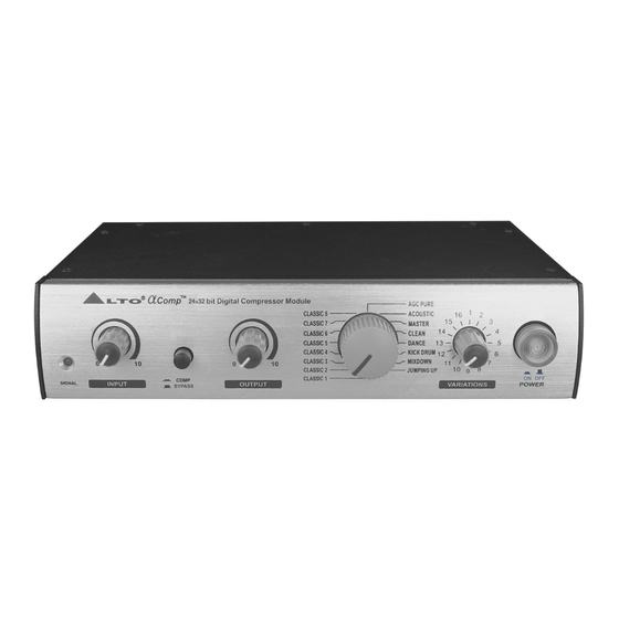
T T M Comp 243 2 bit Digital Compressor Module AGC PURE CLASSIC 8 ACOUSTIC CLASSIC 7 MASTER CLASSIC 6 CLEAN DANCE CLASSIC 5 CLASSIC 4 KICK DRUM CLASSIC 3 MIXDOWN JUMPING UP CLASSIC 2 ON OFF COMP CLASSIC 1 SIGNAL INPUT BYPASS... -
Page 9: Compressor Bypass Pedal Input
- Outputs : These are 1/4" unbalanced phone jacks which connect to devices such as the channel inserts on a mixing console or power amplifier inputs. b. Compressor Bypass Pedal Input - Compressor Bypass : This is a 1/4" phone jack which connects to a footswitch ( with latching ), either normally-open or normally-closed. -
Page 10: Levels Setting
also routed automatically to the RIGHT INPUT. However , if we are using stereo input signals, connecting a cable to the RIGHT INPUT jack , the automatic routing will be avoided and the LEFT INPUT jack will feed only the LEFT INPUT, and the RIGHT INPUT jack will feed only the RIG HT INPUT. b. -
Page 11: Application Examples
b. Application Examples line instrument When connecting audio cables and/or turning power on and off, make sure that all devices in your system have their volume controls turned down. Comp has two 1/4" unbalanced inputs and two 1/4" unbalanced outputs. These input /output configuration may provide three different audio connections options: Connect an audio cable to the [LEFT] INPUT of the... -
Page 12: Mixer
From Stereo Audio Source To Amplifier or Mixing Console Left Input Right Output Left output Right Input T T M Comp 243 2 bit Digital Compressor Module AGC PURE ACOUSTIC CLASSIC 8 CLASSIC 7 MASTER CLEAN CLASSIC 6 DANCE CLASSIC 5 CLASSIC 4 KICK DRUM CLASSIC 3... -
Page 13: Rackmount
Take good care in adjusting Comp input and output levels, in order to satisfy the dynamics needs of both the processe d channels. If you don't hear any sound, try to swap the Input and Output ends of the TRS cable plugged into Comp. -
Page 14: Dynamic Compression Process
Compressor Ratio OUTPUT Max Level AGC Coet = Decreased = f(Comp Speed) Threshold Comp AGC Coef = Constant Threshold Hold AGC Coef =increment = f(Exp Speed) Threshold Exp AGC Coef =Constant Input AGC Coef Min = f(Cmp Ratio) Exp Ratio AGC Coef Max = f(Exp Ratio) 1.Expander Speed: The parameter Expander Speed repre sents the speed with which the signal is expanded beyond the Expander Threshold, this is true only... -
Page 15: Stereo 2 Bands Compressor
Input Output Gain Level Detector Control A compressor's input/output relationship is often described by a simple graph: The horizontal axis corresponds to the input signal level, and the vertical axis is the output level (both measured in decibels) . A line at 45 degrees corresponds to a gain of one - any input level is mapped to exactly the same output level. -
Page 16: Stereo 2 Bands Compressor Presets
This kind of dynamic process is very useful for the dynamic control of complex sounds as the ones coming from CD or orchestras etc. 5.4 Stereo 2 Bands Compressor Presets a. Agc pure This process is a simple automatic level control. Its speed varies with the different 'variation' control positions. -
Page 17: Jumping Up
h. jumping up The sound of Jumping Up Preset is quite similar to Clean Preset as general timbre, but this preset underlines very well male voices and is capable to keep up the level in soft passages of the music program. For female voices the Clean Program is probably better. -
Page 18: Compression Effects Summary Table
have been made thinking for them an use with single instruments. More, the presets are well tailored on classic guitars or acoustic instruments, where different equalizations of the sound can give to the instruments more or less character and deepness, passing from bright equalizations to warmer ones. 5.7 Compression Effects Summary Table LIMITER L i m i t e r L o w... -
Page 19: Technical Specifications
Eq Classic Preset PEQ 1 PEQ 2 PEQ 3 PEQ 4 PEQ 5 G=1dB; F=75Hz ; G=0,5dB; G=1dB; F=12KHz ; Classic 1 G=0dB G=0dB F=1KHz ; Q=1 G=1dB; G=-1dB; G=1dB; F=75Hz ; G=-1dB; F=1KHz ; G=-1dB; Classic 2 F=600Hz ; Q=5 F=3,7KHz ;... -
Page 20: Specifications
6.2 Specifications Electrical Frequency Response: +0.5 / -1.5 dB from 20Hz to 20 kHz S/N Ratio (process) 80 dB "A" wtg, 20 Hz-22kHz S/N Ratio (bypass) >90 dB "A" wtg, 20 Hz-22kHz <0.008% @ 1kHz (0dBV, bypass) THD+Noise: Input Number of Channels: Format: 1/4"... -
Page 21: Warranty
7. Warranty 1. WARRANTY REGISTRATION CARD To obtain Warranty Service, the buyer should first fill out and return the enclosed Warranty Registration Card within 10 days of the Purchase Date. All the information presented in this Warranty Registration Card gives the manu- facturer a better understanding of the sales status, so as to purport a more effective and efficient after-sales warranty service. - Page 22 3.5 In no event shall be liable for any incidental or consequential damages. Some states do not allow the exclusion or limitation of incidental or conse- quential damages, so the above exclusion or limitation may not apply to you. 3.6 This warranty gives you the specific rights, and these rights are compatible with the state laws, you may also have oth er statutory rights that may vary from state to state.
Need help?
Do you have a question about the aComp and is the answer not in the manual?
Questions and answers