
Related Manuals for Alto CLE8.0


Summary of Contents for Alto CLE8.0
- Page 1 User's Manual CLE8.0 COMPRESSOR /LIMITER /GATE www.altoproaudio.com Version 2.4 September 2005 English...
- Page 2 SAFETY RELATED SYMBOLS Fuse To prevent fire and damage to the product, use only the recommended fuse type as indicated in this CAUTION manual. Do not short-circuit the fuse holder. Before RISK OF ELECTRIC SHOCK DO NOT OPEN replacing the fuse, make sure that the product is OFF and disconnected from the AC outlet.
- Page 3 PREFACE Dear Customer: Thanks for choosing LTO CLE 8.0 Compressor/Limter/Gate and thanks for choosing one of the results of AUDIO TEAM job and researches. For our LTO AUDIO TEAM, music and sound are more than a job...are first of all passion and let us say...our obsession! We have been designing professional audio products for a long time in cooperation with some of the major brands in the world in the audio field.
-
Page 4: Table Of Contents
TABLE OF CONTENTS 1. INTRODUCTION............................4 2. THE CONCEPT BEHIND..........................4 2.1 Some technical stuff 2.2 Voltage Controlled Amplifier (VCA) 2.3 Inputs 3. CONTROLS..............................6 3.1 Master Control Section 3.2 Expander / Gate Section 3.3 Compressor Section 3.4 Peak Limiter Section 3.5 The Rear Panel 4. -
Page 5: Introduction
1. INTRODUCTION You are now the Owner of an CLE 8.0 Compressor/Limiter/Gate. The CLE 8.0 is a very powerful dynamic processor. We have included in it several innovative circuit designs that make the CLE 8.0 a very versatile processor: smart and fast recognition of the program, adjustable Expander/Gate and very low distortion Voltage Control Amplifier (VCA). - Page 6 2.1.2 Introducing Audio Dynamics The human ear can detect the noise generating by falling leaves as well as the roar generated by the taking off space shuttle. Unfortunately no analog, nor digital device can reproduce such wide spectrum. Please look at Chart.1 and you will see the difference if dynamic capacity of various devices when compare to the human ear.
-
Page 7: Voltage Controlled Amplifier (Vca)
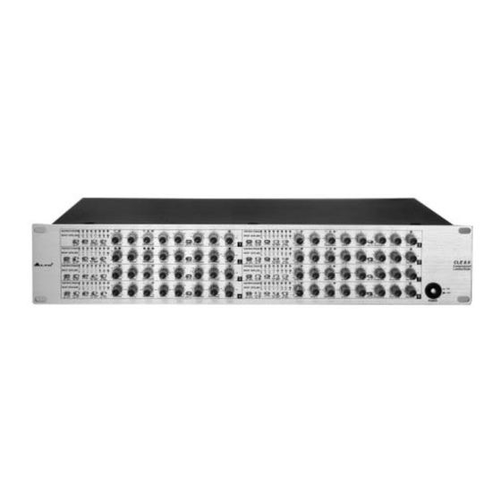
SMART SMART Pic.1: Front Panel of The CLE8.0 The CLE 8.0 presents with 8 channels. Each channel is equipped with the same control elements: 6 push-button switches, 8 rotary controls and 22 LEDs except channel 1 which short of the LINK CH1 push-button only. -
Page 8: Expander / Gate Section
1. Gain Reduction Meter It indicated the gain reduction. The range displayed is 1 to 30 dB. 2. Input / Output Level Meter It will read the actual Input or Output Level. The range goes from -24dB to +18dB. 3. Bypass Switch This switch simply turns off the correspondent channel. -
Page 9: Compressor Section
3.3 Compressor Section 0.05 AUTO COMPRESSOR(dB) RATIO(N:1) ATTACK(mSec) RELEASE(dB/Sec) OUTPUT GAIN(dB) Pic.4: Compressor Section 11. Compressor Control This control adjusts the threshold level for the Compressor section in the range of -40dB to +20dB. The SKC (Smart Knee Control) is applied to the audio signal, which is a maximum of 10dB above the set threshold. Above such level (10dB) a hard knee compression will be applied. -
Page 10: The Rear Panel
CHANNEL 3 CHANNEL 2 CHANNEL 1 Pic.6: Pear Panel Of The CLE8.0 20. AC Inlet and Fuse Holder This connector is used to connect the supplied power cord. Please check the Voltage accepted by the unit and the Voltage available from your AC sockets before connecting the unit to the Mains. -
Page 11: Ready To Roll
4. READY TO ROLL? 4.1 Expander/Gate Section Chart.3: Function of an expander As we told you previously in this Manual the downward expander will reduce automatically the level of the audio signal when such signal is below a set threshold. So the expander is the opposite of the compressor/limiter. We also explained to you how the ratio curve of the expander is flat while a noise gate it is more brutal processor: It simply cut-off the entire signal below a certain set threshold. - Page 12 If you have a ratio of 2:1 this means that for every 2dB increase of the input level (above threshold) you will get an increase of output level of 1dB. ON the same way, a ratio of 10:1 means that for every 10dB increase of the input level (above threshold) you will get an increase in output level equal to 1dB, and so on.
-
Page 13: Peak Limiter Section
Chart.6: The effect of a compressor can be expressed as the amount of gain reduction that is taking place for any given input 4.3 Peak Limiter Section How fast is the compressor to react to a signal which is above the threshold point? This is determined by the attack time. - Page 14 a. Wiring Configuration Both types of connectors available on CLE 8.0 can be wired in balanced and unbalanced modes. Please see following drawing for details: For 1/4" Phone jack For XLR connector Pin2 (+) Pin3 (-) (Linked to Pin1 manually, Pin1 ( ) XLR Type Unbalanced XLR Type alanced...
-
Page 15: Rack Mounting
c. Insert Points Connection In case you are using the main inserts of your mixing console and you have a single jack for SEND and RETURN, you can use an insert Y cable . Please see following drawing. 1/4" TRS insert Send Return Ring... -
Page 16: Technical Specifications
6. TECHNICAL SPECIFICATIONS INPUT Type Active balanced XLR and 1/4"JACK Impedance Balanced >50KOhm, Unbalanced>25KOhm Operating level +4dBu/ 10dBV Max input level +21dBu balanced and unbalanced Typically>55dB at 1KHz CMRR OUTPUT Type XLR and 1/4" JACK Impedance Balanced 60 Ohm, Unbalanced 30 Ohm Max output level >+21dBu RETURN... - Page 17 FUNCTION SWITCHES SMART Enables the "Smart Knee Control" characteristics. Allows for frequency dependent processing. SC FILTER Enable the automatic and program dependent setting of the Attack AUTO /Release times, disengaging the manual Attack /Release controls. Switches between input and output for the Level Meter. I/O METER Bypass switch.
-
Page 18: Warranty
7. WARRANTY 1. WARRANTY REGISTRATION CARD To obtain Warranty Service, the buyer should first fill out and return the enclosed Warranty Registration Card within 10 days of the Purchase Date. All the information presented in this Warranty Registration Card gives the manufacturer a better understanding of the sales status, so as to purport a more effective and efficient after-sales warranty service. - Page 19 SE KAKU TECHNICAL GROUP LIMITED No. 1, Lane 17, Sec. 2, Han Shi West Road, Taichung 40151 Taiwan http://www.altoproaudio.com Tel: 886-4-22313737 email: alto@altoproaudio.com Fax: 886-4-22346757 All rights reserved to ALTO. All features and content might be changed without prior notice. Any photocopy, translation, or reproduction of part of this manual without written permission is forbidden.
Need help?
Do you have a question about the CLE8.0 and is the answer not in the manual?
Questions and answers