
Related Manuals for LG GR-B207WVQ.CSWQAGE


Summary of Contents for LG GR-B207WVQ.CSWQAGE
- Page 1 REFRIGERATOR SERVICE MANUAL CAUTION PLEASE READ CAREFULLY THE SAFETY PRECAUTIONS OF THIS BOOK BEFORE CHECKING OR OPERATING THE REFRIGERATOR . Color:Super White MODEL:GR-B207WVQ.CSWQAGE...
-
Page 2: Table Of Contents
CONTENTS WARNINGS AND PRECAUTIONS FOR SAFETY ........................ 3 SPECIFICATIONS................................... 4 PARTS IDENTIFICATION ................................5 HOW TO INSTALL THE REFRIGER ATOR .......................... 6 HOW TO ADJUST DOOR HEIGHT OF THE REFRIGERATOR ..................6 HOW TO INSTALL WATER PIPE............................6 HOW TO CONTROL THE AMOUNT OF WATER SUPPLIED TO THE ICEMAKER ............7 MICOM FUNCTION ................................ -
Page 3: Warnings And Precautions For Safety
WARNINGS AND PRECAUTIONS FOR SAFETY 8. Do not fray, damage, machine, heavily bend, pull out, Please observe the following safety precautions in order to use safely and correctly the refrigerator and to prevent or twist the power cord. accident and danger during repair. 9. -
Page 4: Specifications
SPECIFICATIONS 3. Model spec. ITEMS SPECIFICATIONS ITEMS SPECIFICATIONS DIMENSIONS (mm) 894(W) 725(D) 1753(H) CAPILLARY TUBE MOLECULAR SIEVE XH-7 NET WEIGHT (kg) FIRST DEFROST 4 - 5 Hours COOLING SYSTEM Fan Cooling DEFROST CYCLE 13 - 15 Hours TEMPERATURE CONTROL Micom Control DEFROSTING DEVICE Heater, Sheath DEFROSTING SYSTEM... -
Page 5: Parts Identification
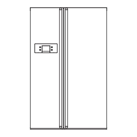
PARTS IDENTIFICATION 2. Ref No. Cover PWB Frame Display Conversion switch (Meats/Vegetables) - 5-... - Page 6 HOW TO INSTALL REFRIGER ATOR 1. How to Adjust Door Height of Refrigerator Even if the height can not be aligned by Make the refrigerator level first. (If the refrigerator is not installed using the height adjustment screw,insert on the flat floor, the height of freezer and refrigerator door may the transparent sheet supplied with the not be the same.
- Page 7 HOW TO INSTALL REFRIGER ATOR Install Water Filter (Applicable to some models only) Before Installing water filter Control box 1. Before installing the filter, take out the top shelf of the refrigerator after tilting it to the direction ( ) and lifting it to the direction ( ) and move it to the lower part.
-
Page 8: Micom Function
MICOM FUNCTION 1. Monitor Panel 1. 88 LED Function display board FREEZER REFRIGERATOR EXPRESS FRZ. CHILD LOCK 3secs Express freezer Lock button Temperature adjustment botton Temperature adjustment botton for refrigerator compartment for freezer compartment 2. Description of Function 2-1. Funnction of Temperature Selection Divisio n Power Initial ly On 1st Pres s... - Page 9 MICOM FUNCTION 2-2. Control of variable type of freezing room fan 1. To increase cooling speed and load response speed, MICOM variably controls freezing room fan motor at the high speed of RPM and standard RPM. 2. MICOM only operates in the input of initial power or special freezing operation or load response operation for the high speed of RPM and operates in the standard RPM in other general operation.
- Page 10 MICOM FUNCTION 2-7. Frost removal function 1. Frost removal is performed whenever total operation time of compressor becomes 7 ~ 7.5 hour. 2. In providing initial power (or returning power failure), frost removal starts whenever total operation time of compressor becomes 4 ~ 4.5 hour.
- Page 11 MICOM FUNCTION 2-9. Function of Trouble Diagnosis(88-LED) 1. Failure diagnosis function is function to facilitate service when nonconforming matters affecting performance of product during use of product. 2. In occurrence of failure, pressing the function adjustment button does not perform function and only alarm sound (“Ding~”) rings. 3.
- Page 12 MICOM FUNCTION Note1) In error of outside sensor, setting temperature for freezing/ cold storage is normally displayed and indicated “Er” on the outside temperature display part (normally displayed except for the outside temperature display part). Note2) Nonconforming contents of poor R2 sensor, ice-making sensor and ice-making kit are displayed in LED check, not indicated on the failure display part (when pressing freezing temperature adjustment button and special freezing button for a second or more).
-
Page 13: Explation For Micom Circuit
EXPLATION FOR MICOM CIRCUIT 1. Explanation for PWB circuit 1-1. Power circuit Voltage of every part is as follows: Part Voltage 220 Vac 14 Vdc 17 Vdc 12 Vdc 5Vdc 1-2. Oscillation circuit Oscillation circuit is a circuit with the purpose of generating basic time for clock occurrence for synchronization and time calculation in relation with information transmission/reception of inside elements of IC1 (MICOM). - Page 14 EXPLATION FOR MICOM CIRCUIT 2) GC-B207W The fan motor at the freezing room does not stop but operates if opening doors of the freezing room or cold storage room or the home bar during operation of the fan motor at the freezing room. (A), (B), (C) and (D) of door switch for the freezing room or cold storage room are connected to the door open sensing circuit toward both ends of switch to determine door open at MICOM.
- Page 15 EXPLATION FOR MICOM CIRCUIT 2.Buzzer driving circuit CONDITIONS Bell sounds when button on Beep sounds when warning dosplay is pressed. door opening. MEASURING POINTS 0.05 s 0.2 s 0.1 s 0.4 s 0.5 s 0.5 s IC1 (No. 50 Pin) IC1 (No.
- Page 16 EXPLATION FOR MICOM CIRCUIT 1-5. Switch entry circuit The following circuits are entry circuits for sensing signal form test S/W, electronic single motor damper reed S/W for examining refrigerator. 1-6. Option designation circuit (model separation function) The above circuits are used for designating separation by model as option and notifying it to MICOM. Designation of option by model and the application standards are as follows: These circuits are accurately pre-adjusted in shipment from factory and so you must not additionally add or remove option.
- Page 17 EXPL A TION FOR MICOM CIRCUIT Explanation) For driving method of the stepping moto r , send signals in the cycle of 3.33 mSEC using terminal of MICO PIN 33, 34 and 35 as shown in wave form of the following part. These signals are output to the output terminal (No.10, 11, 14, 15) via the input terminal (No.
- Page 18 EXPLATION FOR MICOM CIRCUIT u Temperature compensation table at the refrigerator room is as follows: Modification resistance 470 Ω 2 kΩ 3.3 kΩ 5.6 kΩ 8.2 kΩ 10 kΩ 12 kΩ 18 kΩ 33 kΩ 56 kΩ 180 kΩ Current resistance 0.5 °C 1 °C...
- Page 19 EXPLATION FOR MICOM CIRCUIT 1-9 . Compensation circuit for weak-cold, over-cold at freezin g room Temperature compensation in CUT JCR1 JCR2 JCR3 JCR4 Compensation Compensation Temperature compensation value for weak-cold for over-cold Remarks at cold storage room JCR3 JCR4 JCR1 JCR2 0 °C (In shipment from factory) -1 °C...
- Page 20 EXPLATION FOR MICOM CIRCUIT 1-10. Key Button Input and Display Lighting Circuit This circuit is to judge the work of function control button on the operation panel and to light each function indication led (LED module). It is driven by SCAN method. - 21-...
- Page 21 EXPLATION FOR MICOM CIRCUIT 1-11 Sensor resistance characteristics table Refrigerator sensor 1&2 Measuring Temperature ( ° C) Freezing Sensor Defrost sensor, Ambient sensor -20 ° C 22.3 kΩ 77 kΩ -15 ° C 16.9 kΩ 60 kΩ 47.3 k Ω -15 °...
-
Page 22: Pwb Parts Drawing And List
EXPLATION FOR MICOM CIRCUIT 2.PWB Parts Drawings and List 2-1.PWB Assembly Main Parts Drawings... - Page 23 EXPLATION FOR MICOM CIRCUIT 3 - 1 . Parts List WORK DESCRIPTION SPEC MAKER REMARK P/NO 6870JB8201C PWB(PCB) VIKING-PJT BEST BASIC VER-2 DOOSAN T=1.6 6870JB8201D PWB(PCB) DOOSAN T=1.6 VIKING-PJT BEST BASIC M/ROOM VER-2 6170JB2012A TRANSFORMER,SMPS[COIL] DL-PJT 2.9MH/20W SAM IL, TRANS 6170JB2012C TRANSFORMER,SMPS[COIL] GR-B217/257*A(G) BLDC 100-127V...
- Page 24 EXPLATION FOR MICOM CIRCUIT 3 - 2 . Parts List WORK P/NO DESCRIPTION SPEC MAKER REMARK 6854B50001A JUMP WIRE 0.6MM (52)MM TP TAPING SN DAE A LEAD (R)J1 0RD1001G609 RESISTOR,FIXED CARBON FILM 1K OHM 1/4 W 5% TA52 SMART,CHOHYANG (R)J1 0RD1801G609 RESISTOR,FIXED CARBON FILM 1.8K OHM 1/4 W 5% TA52...
- Page 25 CIRCUIT The circuit has been only applied to voltage except 220v. - 52 -...
-
Page 26: Trouble Diagnosi S
TROUBLE DIAGNOSIS 1. TROUBLE SHOOTING CLAIMS. CAUSES AND CHECK POINTS. HOW TO CHECK 1) No power on outlet. * Measuring instrument : 1. Faulty start Multi tester 2) No power on cord. I Check the voltage. Bad connection between adapter and outlet. (faulty adapter) The Inner diameter of adapter. -
Page 27: Trouble Diagnosis
TROUBLE DIAGNOSIS CLAIMS. CAUSES AND CHECK POINTS. HOW TO CHECK I Check the clogged 2. No cooling. 2) Refrigeration system is clogged. evaporator by heating (as Moisture Residual moisture Air Blowing. Not performed. soon as the cracking sound clogged. in the evaporator. Too short. - Page 28 TROUBLE DIAGNOSIS CLAIMS. CAUSES AND CHECK POINTS. HOW TO CHECK 3. Refrigeration 1) Refrigerant Partly leaked. Weld joint leak. is weak. Parts leak. 2) Poor defrosting capacity. I Check visually. Drain path (pipe) clogged. Inject P/U into drain hose. Inject through the hole.
-
Page 29: Faults
TROUBLE DIAGNOSIS CLAIMS. CAUSES AND CHECK POINTS. HOW TO CHECK 3. Refrigeration Residual Weak heat from heater. Sheath Heater - rated. is weak. frost. Heater plate - rated. Too short defrosting time. Defrost Sensor. - Faulty characteristics. Seat-D(missing, location. thickness). Structural fault. - Page 30 TROUBLE DIAGNOSIS CLAIMS. CAUSES AND CHECK POINTS. HOW TO CHECK 3. Refrigeration 4) No cooling air circulation. is weak. Faulty fan motor. Fan is Fan shroud contact. - Clearance. constrained. Damping evaporator contact. Accumulated residual frost. Small cooling air Insufficient Fan overload.
- Page 31 TROUBLE DIAGNOSIS CLAIMS. CAUSES AND CHECK POINTS. HOW TO CHECK 4. Warm 1) Colgged cooling path. refrigerator P/U liquid leak. compartment Foreign materials. –– P/U dump liquid. temperature. 2) Food storate. Store hot food. Store too much at once. Door open. Packages block air flow.
- Page 32 TROUBLE DIAGNOSIS CLAIMS. CAUSES AND CHECK POINTS. HOW TO CHECK 6. Dew and 4) Dew on door. ice formation. Dew on the duct door. - Duct door heater is cut. Dew on the dispense Recess Heater is cut. recess. Duct door is open. / Foreign material clogging. Dew on the door surface.
- Page 33 TROUBLE DIAGNOSIS CLAIMS. CAUSES AND CHECK POINTS. HOW TO CHECK 7. Sounds 1) Compressor compartment operating sounds. Transformer sound. Its own fault. –– Core gap. Bad connection. –– Correct screw connection. Drip tray vibration sound. Bad assembly. Distortion. Foreign materials inside. Back cover machine sound.
- Page 34 TROUBLE DIAGNOSIS CLAIMS. CAUSES AND CHECK POINTS. HOW TO CHECK 8. Faulty lamp 1) Lamp problem. Filament blows out. (freezer and Glass is broken. refrigerator 2) Bad lamp assembly. Not inserted. compartment). Loosened by vibration. 3) Bad lamp socket. Disconnection. Bad soldering.
- Page 35 TROUBLE DIAGNOSIS CLAIMS. CAUSES AND CHECK POINTS. HOW TO CHECK 10. Structure, 1) Door foam. appearance Sag. Weak torque of Bolt is loosened during and others. hinge connection. transportaion. Not tightly fastened. Screw worn out . Weak gasket Adhesion surface. adhesion.
- Page 36 TROUBLE DIAGNOSIS...
- Page 37 TROUBLE DIAGNOSIS - 3 8...
- Page 38 TROUBLE DIAGNOSIS...
- Page 39 TROUBLE DIAGNOSIS...
- Page 40 TROUBLE DIAGNOSIS...
- Page 41 TROUBLE DIAGNOSIS...
- Page 42 TROUBLE DIAGNOSIS...
- Page 43 TROUBLE DIAGNOSIS 44 -...
- Page 44 TROUBLE DIAGNOSIS - 45...
- Page 45 TROUBLE DIAGNOSIS - 4 6...
- Page 46 TROUBLE DIAGNOSIS - 4 7...
- Page 47 TROUBLE DIAGNOSIS - 4 8...
- Page 48 TROUBLE DIAGNOSIS - 4 9...
- Page 49 TROUBLE DIAGNOSIS - 5 0...
- Page 50 TROUBLE DIAGNOSIS - 5 1...
- Page 51 TROUBLE DIAGNOSIS...
- Page 52 TROUBLE DIAGNOSIS - 5 3...
-
Page 53: Cooling Cycle Heavy Repair
TROUBLE DIAGNOSIS 3. Cooling Cycle Heavy Repair 3-1. The Heavy Repair Standards for Refrigerator with R134a Refrigerant Items Unit Standards Purposes Remarks Pipe and piping Min. Pipe:within 1 hour. To protect The opening time should be reduced to a system opening time. Comp:within Moisture half of the standards during rain and... - Page 54 TROUBLE DIAGNOSIS 3-2. Summary Of Heavy Repair Process Contents Tools Trouble diagnosis Remove refrigerant - Cut charging pipe ends and discharge refrigerant from Filter, side cutters Residuals drier and compressor. - Use R134a oil and refrigerant for compressor and drier Pipe Cutter, Gas welder, N - Confirm N sealing and packing conditions before use.
- Page 55 TROUBLE DIAGNOSIS 3-4. Practical Work For Heavy Repair Items Precautions Evaporator 1. Removal of residual Low pressure side refrigerant. KEYPOINTING Compressor Observe the sequence for removal of refrigerant. Drier Suction (If not, compressor oil may leak.) Release High pressure side Condenser Refrigent Intake...
- Page 56 TROUBLE DIAGNOSIS 3-3. Precautions During Heavy Repair Items Precautions 1. Use of tools. 1) Use special parts and tools for R134a. 2. Removal of retained 1) Remove retained refrigerant more than 5 minutes after turning off a refrigerator. refrigerant. (If not, oil will leak inside.) 2) Remove retained refrigerant by cutting first high pressure side (drier part) with a nipper and then cut low pressure side.
- Page 57 TROUBLE DIAGNOSIS Items Precautions 4.Vacuum degassing. Evaporator Suction pipe Compressor Drier Condenser pressure High Blue pressure Yellow Vaccum KEYPOINTING Pump - If power is applied during vacuum degassing, vacuum degassing shall be more effective. Pipe Connection - Operate compressor Connect a red hose to the high pressure side and a blue hose to the while charging refrigerant.
- Page 58 TROUBLE DIAGNOSIS Items Precautions Evaporator Compressor Drier Condenser Bombe 4) Refrigerant Charging Charge refrigerant while operating a compressor as shown above. 5) Pinch a charging pipe with a pinch-off plier after completion of charging. 6) Braze the end of a pinched charging pipe with copper brazer and take a gas leakage test on the welded parts.
- Page 59 TROUBLE DIAGNOSIS 3-6. Brazing Reference Drawings GC-B207WLQ.CPLQMAG Area: M Asia PIPE ASSEMBLY PIPE ASSEMBLY HOT LINE HOT LINE (Refrigerator) (Freezer) Copper(Silver) Copper Brazer Brazer CAPI - TUBE DRIER ASSEMBLY Copper(Silver) Silver Brazer Brazer PIPE ASSEMBLY JOINT PIPE ASSEMBLY SUCTION Copper Brazer PIPE ASSEMBLY CONDENSER ASSEMBLY WIRE...
-
Page 60: How To Deal With Claims
TROUBLE DIAGNOSIS 4. HOW TO DEAL WITH CLAIMS 4-1. Sound Problems Checks and Measures I Explain general principles of sounds. "Whizz" sounds • All refrigerator when functioning properly have normal operating sound. The compressor and fan produce sounds. There is a fan in the freezer compartment which blows cool air to freezer and refrigerator compartments. - Page 61 TROUBLE DIAGNOSIS Problems Checks and Measures I Explain the flow of refrigerant. Sounds of water flowing • When the refrigerator stops, the water flowing sound happens. This sound happens when the liquid or vapor refrigerant flows from the evaporator to compressor. I Explain the characteriistics of moving parts.
- Page 62 TROUBLE DIAGNOSIS 4-2. Measures for Symptoms on Temperature Problems Checks and Measures I Check temperature set in the temperature control knob. Refrigeration is weak. • Refrigerator is generally delivered with the button set at “normal use” (MID). But customer can adjust the temperature set depending on their habit and taste. If you feel the refrigeration is weak, then set the temperature control button at “strong”...
- Page 63 TROUBLE DIAGNOSIS 4-3. Odor and Frost Problems Checks and Measures I Explain the basic principles of food odor. Odor in the refrigerator compartment. • Each food has its own peculiar odor. Therefore it is impossible to prevent or avoid food odor completely when food is stored in the completely sealed refrigerator compartment.
- Page 64 TROUBLE DIAGNOSIS 4-4. Others Problems Checks and Measures I Explain the principles of radiator. The refrigerator case is hot. • The radiator pipes are installed in the refrigerator case and partition plate between the refrigerator and the freezer compartment in order to prevent condensation formation.
-
Page 65: How To Disassemble And Assembl E
HOW TO DISASSEMBLE AND ASSEMBLE 1. DOOR (3) Disconnect upper hinge from a hinge supporter 1) Remove lower cover and remove clip then by grasping the front part of upper hinge and lifting up disconnect water supply tube in the lower part (Hinge Assembly, U) in arrow direction A and pull of freezer door. -
Page 66: Handle
HOW TO DISASSEMBLE AND ASSEMBLE 2. HANDLE 4. ICEMAKER ASSEMBLY 1. Dispenser Model ① Hit the location in the direction of arrow to loose. 1) 1) How to disassemble: 2) Lift the handle up with hands in the direction of arrow (1) Remove ice bank from the freezer compartment. -
Page 67: Exploded View
EXPLODED VIEW FREEZER DOOR P A R T 200A 205A 202A 210B 205F 210B 205B 205D 210B 210C 205C 207A 279A 501A 210C 201A 203A 280E 279B 280D... - Page 68 EXPLODED VIEW REFRIGERATOR DOOR P A R T 241C 230A 232A 241A 241B 239A 205A 147A 243A 240B 205F 243A 205B 240B 205D 240C 231A 233A 205C 240C...
-
Page 69: Freezer Compartment
EXPLODED VIEW FREEZER COMPARTMENT 131J 154A 131E 101A 270A 131B 271B 271A 137B 131C 131H 137A 136D 131D 132A 403A 402A 136C 136B 136A 152A 135A 137C 120D 316B 302B 409B 128C 120B 128D 130A 120B 128E 120C 400A 128F 125A 126A 272A... - Page 70 EXPLODED VIEW REFRIGER A T OR COM P A R TMENT 140A 141A 140A 101B 146A 171A 270B 171B 271B 271C 170A 115A 140A 116A 115B 402B 115F 151A 152A 151C 151B 409B 177A 166B 177B 166C 162A 150A 155A 166A 162B 272B...
- Page 71 EXPLODED VIEW MACHINE COM P A R TMENT 406A 502A 407B 407A 303A 500A 303B 502B 304A 303C 303D 313A 316A 300A 310B 307A 317A 307A 301A 317B 104A 308B 306A 309A 309B 305A 403B 305B 310A 309C 305C 308A 308C 105E 305C...
Need help?
Do you have a question about the GR-B207WVQ.CSWQAGE and is the answer not in the manual?
Questions and answers